EP4575997A1 - Génération d'images synthétiques - Google Patents
Génération d'images synthétiques Download PDFInfo
- Publication number
- EP4575997A1 EP4575997A1 EP23217696.6A EP23217696A EP4575997A1 EP 4575997 A1 EP4575997 A1 EP 4575997A1 EP 23217696 A EP23217696 A EP 23217696A EP 4575997 A1 EP4575997 A1 EP 4575997A1
- Authority
- EP
- European Patent Office
- Prior art keywords
- examination
- images
- machine learning
- learning model
- synthetic
- Prior art date
- Legal status (The legal status is an assumption and is not a legal conclusion. Google has not performed a legal analysis and makes no representation as to the accuracy of the status listed.)
- Pending
Links
Images

Classifications
-
- G—PHYSICS
- G06—COMPUTING OR CALCULATING; COUNTING
- G06T—IMAGE DATA PROCESSING OR GENERATION, IN GENERAL
- G06T11/00—Two-dimensional [2D] image generation
-
- G—PHYSICS
- G06—COMPUTING OR CALCULATING; COUNTING
- G06V—IMAGE OR VIDEO RECOGNITION OR UNDERSTANDING
- G06V10/00—Arrangements for image or video recognition or understanding
- G06V10/70—Arrangements for image or video recognition or understanding using pattern recognition or machine learning
- G06V10/77—Processing image or video features in feature spaces; using data integration or data reduction, e.g. principal component analysis [PCA] or independent component analysis [ICA] or self-organising maps [SOM]; Blind source separation
- G06V10/774—Generating sets of training patterns; Bootstrap methods, e.g. bagging or boosting
-
- G—PHYSICS
- G06—COMPUTING OR CALCULATING; COUNTING
- G06T—IMAGE DATA PROCESSING OR GENERATION, IN GENERAL
- G06T2210/00—Indexing scheme for image generation or computer graphics
- G06T2210/41—Medical
Definitions
- Systems, methods, and computer programs disclosed herein relate to training a machine learning model and using the trained machine learning model to generate synthetic images, preferably synthetic medical images.
- Machine learning models are being used not only to recognize signs of disease in medical images of the human or animal body (see, for example, WO2018202541A1 , WO2020229152A1 ), but also increasingly to generate synthetic (artificial) medical images.
- WO2019/074938A1 and WO2022184297A1 describe methods for generating an artificial radiologic image showing an examination region of an examination object after application of a standard amount of a contrast agent, although only a smaller amount of contrast agent than the standard amount was applied.
- the standard amount is the amount recommended by the manufacturer and/or distributor of the contrast agent and/or the amount approved by a regulatory authority and/or the amount listed in a package insert for the contrast agent.
- the methods described in WO2019/074938A1 and WO2022184297A1 can therefore be used to reduce the amount of contrast agent.
- WO2021052896A1 and WO2021069338A1 describe methods for generating an artificial medical image showing an examination region of an examination object in a first time period.
- the artificial medical image is generated using a trained machine learning model based on medical images showing the examination region in a second time period.
- the method can be used, for example, to speed up radiological examinations. Instead of measuring radiological images over a longer period of time, radiological images are measured only within a part of the time period and one or more radiological images are predicted for the remaining part of the time period using the trained model.
- US11170543B2 B2 and US11181598B2 describe methods for MRI image reconstruction from undersampled data using machine learning models.
- WO2016/175755A1 and WO2014/036473A1 describe methods for generating a high radiation dose CT image based on a low radiation dose CT image using machine learning models.
- Each synthetic two-dimensional (2D) image is generated based on one or more measured two-dimensional (2D) images.
- the number of 2D images in a stack of 2D images is not always the same for different examination objects.
- the number of 2D images forming a stack can vary greatly. The varying number of images in a stack makes it difficult to train a machine learning model and use the trained model to generate synthetic images.
- the present disclosure provides a computer system comprising:
- the present disclosure provides a non-transitory computer readable storage medium having stored thereon software instructions that, when executed by a processor of a computer system, cause the computer system to execute the following steps:
- the articles “a” and “an” are intended to include one or more items and may be used interchangeably with “one or more” and “at least one.”
- the singular form of “a”, “an”, and “the” include plural referents, unless the context clearly dictates otherwise. Where only one item is intended, the term “one” or similar language is used.
- the terms “has”, “have”, “having”, or the like are intended to be open-ended terms. Further, the phrase “based on” is intended to mean “based at least partially on” unless explicitly stated otherwise.
- the present disclosure provides means for generating a stack of synthetic images.
- synthetic means that the image is not the result of a physical measurement on a real object under examination, but that the image has been generated by a machine learning model.
- a synonym for the term “synthetic” is the term “artificial”.
- a synthetic image may however be based on one or more measured images, i.e., the machine learning model may be able to generate the synthetic image based on one or more measured images (and/or other/further data).
- a "stack of images” represents a three-dimensional (3D) volume in an examination object.
- Each image of the stack represents a layer in the three-dimensional (3D) volume of the examination object.
- Such a layer is also referred to as a “slice” in this disclosure.
- the three-dimensional volume is also referred to as the "examination region” in this disclosure.
- Slices of a stack are usually (but necessarily) planar and arranged parallel to each other.
- An “anatomical plane” refers to an imaginary flat surface or section used as a reference to visualize and study the internal structures of the human body. These anatomical planes are useful for describing the location of organs, bones, blood vessels, and other structures within the body. They provide a standardized reference system for medical imaging, surgical procedures, and anatomical studies, facilitating clear communication and accurate interpretation of anatomical relationships.
- the “sagittal plane” divides the body into left and right portions. It runs longitudinally from front to back, creating a side view.
- the “midsagittal plane” (or median plane) is a specific sagittal plane that divides the body into equal left and right halves.
- frontal plane also known as the “coronal plane” divides the body into front (anterior) and back (posterior) portions. It runs vertically from side to side, creating a front or back view.
- the “transverse plane” also called the “horizontal plane” or “axial plane” divides the body into upper (superior) and lower (inferior) portions. It runs horizontally, perpendicular to the sagittal and frontal planes, creating a top or bottom view.
- Slices can therefore be parallel to the sagittal plane, to the frontal plane or to the transverse plane. But they can also be oriented differently.
- machine learning model of the present invention can be trained using training data in which the slices are arranged differently for different examination objects.
- the "examination object” is preferably a living being, more preferably a mammal, most preferably a human.
- the "examination region” is a part of the examination object, for example an organ or part of an organ or a plurality of organs or another part of the examination object.
- the examination region may be a liver, kidney, heart, lung, brain, stomach, bladder, prostate, intestine, thyroid, eye, breast or a part of said parts or another part of the body of a mammal (for example a human).
- a mammal for example a human
- the examination region includes a liver or part of a liver or the examination region is a liver or part of a liver of a mammal, preferably a human.
- the examination region includes a brain or part of a brain or the examination region is a brain or part of a brain of a mammal, preferably a human.
- the examination region includes a heart or part of a heart or the examination region is a heart or part of a heart of a mammal, preferably a human.
- the examination region includes a thorax or part of a thorax or the examination region is a thorax or part of a thorax of a mammal, preferably a human.
- the examination region includes a stomach or part of a stomach or the examination region is a stomach or part of a stomach of a mammal, preferably a human.
- the examination region includes a pancreas or part of a pancreas or the examination region is a pancreas or part of a pancreas of a mammal, preferably a human.
- the examination region includes a kidney or part of a kidney or the examination region is a kidney or part of a kidney of a mammal, preferably a human.
- the examination region includes one or both lungs or part of a lung of a mammal, preferably a human.
- the examination region includes a thyroid or part of a thyroid of a mammal, preferably a human.
- the examination region includes an eye or part of an eye of a mammal, preferably a human.
- the examination region includes a breast or part of a breast or the examination region is a breast or part of a breast of a female mammal, preferably a female human.
- the examination region includes a prostate or part of a prostate or the examination region is a prostate or part of a prostate of a male mammal, preferably a male human.
- image means preferably a data structure that represents a spatial distribution of a physical signal.
- the spatial distribution may be of any shape, for example forming a grid and thereby defining pixels or voxels, the grid being possibly irregular or regular.
- the physical signal may be any signal, for example proton density, tissue echogenicity, tissue radiolucency, measurements related to the blood flow, information of rotating hydrogen nuclei in a magnetic field, color, level of gray, depth, surface or volume occupancy, such that the image may be a 2D RGB/grayscale/depth image.
- An image is usually composed of discrete image elements (pixels).
- the present invention is described in this disclosure predominantly using the example of images representing an examination region of an examination object in real space.
- the present invention can also be applied to representations of an examination region in other spaces, for example, representations of the examination region in frequency space or projection space.
- image is to be interpreted broadly.
- the "real space” is the three-dimensional Euclidean space, which corresponds to the space that we humans experience with our senses and in which we move. A representation in real space is therefore the more familiar representation for humans.
- the examination region is usually represented by a plurality of image elements, which may for example be in a raster arrangement in which each image element represents a part of the examination region, wherein each image element may be assigned a colour value or grey value.
- the colour value or grey value represents a signal intensity, for example the attenuation of X-rays.
- the examination region is represented by a superposition of fundamental vibrations.
- the examination region may be represented by a sum of sine and cosine functions having different amplitudes, frequencies, and phases.
- the amplitudes and phases may be plotted as a function of the frequencies, for example, in a two- or three-dimensional plot.
- the lowest frequency (origin) is placed in the centre. The further away from this centre, the higher the frequencies.
- Each frequency can be assigned an amplitude representing the frequency in the frequency-space representation and a phase indicating the extent to which the respective vibration is shifted towards a sine or cosine vibration.
- the k-space data produced by MRI is an example of a representation in frequency space.
- a representation in real space can for example be converted (transformed) by a Fourier transform into a representation in frequency space.
- a representation in frequency space can for example be converted (transformed) by an inverse Fourier transform into a representation in real space.
- a "medical image” is a preferably visual representation of the human body or a part thereof or a visual representation of the body of an animal or a part thereof. Medical images can be used, e.g., for diagnostic and/or treatment purposes.
- Examples of medical images include CT (computer tomography) scans, X-ray images, MRI (magnetic resonance imaging) scans, PET (positron emission tomography) scans, fluorescein angiography images, OCT (optical coherence tomography) scans, histological images, ultrasound images, fundus images and/or others.
- CT computer tomography
- X-ray images MRI (magnetic resonance imaging) scans
- PET positron emission tomography
- fluorescein angiography images fluorescein angiography
- OCT optical coherence tomography
- the medical image is a radiologic image.
- Radiology is the branch of medicine concerned with the application of electromagnetic radiation and mechanical waves (including, for example, ultrasound diagnostics) for diagnostic, therapeutic and/or scientific purposes.
- X-rays other ionizing radiation such as gamma rays or electrons are also used.
- imaging other imaging procedures such as sonography and magnetic resonance imaging (MRI) are also included in radiology, although no ionizing radiation is used in these procedures.
- MRI magnetic resonance imaging
- the term "radiology” as used in the present disclosure includes, in particular, the following examination procedures: computed tomography, magnetic resonance imaging, sonography, positron emission tomography.
- the radiologic image can be, e.g., a 2D or 3D CT scan or MRI scan.
- the radiologic image may be a representation of an examination region generated with or without a contrast agent.
- Contrast agents are substances or mixtures of substances that improve the depiction of structures and functions of the body in radiological examinations.
- contrast agents In computed tomography, iodine-containing solutions are usually used as contrast agents.
- MRI magnetic resonance imaging
- superparamagnetic substances for example iron oxide nanoparticles, superparamagnetic iron-platinum particles (SIPPs)
- paramagnetic substances for example gadolinium chelates, manganese chelates, hafnium chelates
- sonography liquids containing gas-filled microbubbles are usually administered intravenously. Examples of contrast agents can be found in the literature (see for example A.S.L. Jascinth et al.: Contrast Agents in computed tomography: A Review, Journal of Applied Dental and Medical Sciences, 2016, vol.
- the synthetic image is generated with the help of a trained machine learning model.
- Such a “machine learning model”, as used herein, may be understood as a computer implemented data processing architecture.
- the machine learning model can receive input data and provide output data based on that input data and on parameters of the machine learning model (model parameters).
- the machine learning model can learn a relation between input data and output data through training. In training, parameters of the machine learning model may be adjusted in order to provide a desired output for a given input.
- the process of training a machine learning model involves providing a machine learning algorithm (that is the learning algorithm) with training data to learn from.
- the term "trained machine learning model” refers to the model artifact that is created by the training process.
- the training data must contain the correct answer, which is referred to as the target.
- the learning algorithm finds patterns in the training data that map input data to the target, and it outputs a trained machine learning model that captures these patterns.
- input data are inputted into the machine learning model and the machine learning model generates an output.
- the output is compared with the (known) target.
- Parameters of the machine learning model are modified in order to reduce the deviations between the output and the (known) target to a (defined) minimum.
- a loss function can be used for training, where the loss function can quantify the deviations between the output and the target.
- the aim of the training process can be to modify (adjust) parameters of the machine learning model in order to reduce the loss to a (defined) minimum.
- a machine learning model is trained to generate synthetic images.
- the machine learning model is provided.
- the machine learning model is configured to generate a synthetic image based on input data and parameters of the machine learning model.
- the machine learning model can be or include an artificial neural network.
- An "artificial neural network” is a biologically inspired computational model.
- An ANN usually comprises at least three layers of processing elements: a first layer with input neurons (nodes), a k th layer with output neurons, and k-2 inner layers, where k is a natural number greater than 2.
- the input neurons serve to receive the input data.
- the input data constitute or comprise an n-dimensional vector (e.g., a feature vector), with n being an integer equal to or greater than 1, there is usually one input neuron for each component of the vector.
- the input data constitute or comprise an image, there is usually one input neuron for each colour/greyscale channel of each image element.
- the output neurons serve to output a synthetic image.
- the processing elements of the layers are interconnected in a predetermined pattern with predetermined connection weights therebetween.
- Each network node represents a pre-defined calculation of the weighted sum of inputs from prior nodes and a non-linear output function. The combined calculation of the network nodes relates the inputs to the outputs.
- an ANN can also comprise connection biases.
- the machine learning model can be or comprise a convolutional neural network (CNN).
- CNN convolutional neural network
- a "CNN” is a class of deep neural networks, most commonly applied to processing images.
- a CNN comprises an input layer with input neurons, an output layer with output neurons, as well as multiple hidden layers between the input layer and the output layer.
- the nodes in the CNN input layer are usually organized into a set of "filters" (feature detectors), and the output of each set of filters is propagated to nodes in successive layers of the network.
- the computations for a CNN include applying the convolution mathematical operation to each filter to produce the output of that filter.
- Convolution is a specialized kind of mathematical operation performed by two functions to produce a third function that is a modified version of one of the two original functions.
- the first function to the convolution can be referred to as the input, while the second function can be referred to as the convolution kernel.
- the output may be referred to as the feature map.
- the input to a convolution layer can be a multidimensional array of data that defines the various colour/greyscale components of an input image.
- the convolution kernel can be a multidimensional array of parameters, where the parameters are adapted by the training process for the neural network.
- the objective of the convolution operation is to extract features (such as, e.g., edges from an input image).
- the first convolutional layer is responsible for capturing the low-level features such as edges, colour, gradient orientation, etc.
- the architecture adapts to the high-level features as well, giving a network which has the wholesome understanding of images in the dataset.
- the pooling layer is responsible for reducing the spatial size of the feature maps. It is useful for extracting dominant features with some degree of rotational and positional invariance, thus maintaining the process of effectively training of the model.
- Adding a fully-connected layer is a way of learning non-linear combinations of the high-level features as represented by the output of the convolutional part.
- the machine learning model can have an autoencoder architecture.
- An “autoencoder” is a type of neural network that is often used for unsupervised learning and dimensionality reduction.
- An autoencoder is designed to learn a compressed representation (encoding) of the input data and subsequently reconstruct (decode) the original input as accurately as possible or generate an output derived from the input data.
- An autoencoder usually consists of two main components: the encoder and the decoder.
- the encoder maps the input data to a lower-dimensional space, typically referred to as the latent space or bottleneck.
- the dimensionality of this latent space is usually smaller than the dimensionality of the input data, effectively compressing the information.
- the decoder then reconstructs the original input from the encoded representation using another neural network, mirroring the encoder's structure. However, the decoder can also be used to generate a different output from the encoded representation, e.g., a synthetic image.
- the machine learning model can have a U-Net architecture.
- U-Net refers to a convolutional neural network (CNN) architecture that was introduced by Ronneberger et al. in 2015 (see, e.g., O. Ronneberger et al.: U-Net: Convolutional Networks for Biomedical Image Segmentation, arXiv:1505.04597v1 ).
- CNN convolutional neural network
- the U-Net architecture is notable for its symmetric and U-shaped structure, which inspired its name. It is designed to capture both local and global information while maintaining fine-grained spatial resolution.
- the U-Net architecture typically consists of two main parts: the contracting path (encoder) and the expansive path (decoder).
- the contracting path in the U-Net architecture resembles a traditional CNN, where each layer consists of convolutional and pooling operations. As the name suggests, this part of the network is responsible for capturing the low-level and high-level features, gradually reducing the spatial resolution and increasing the number of feature channels.
- the expansive path in the U-Net architecture which is the decoder part, performs a series of upscaling operations to gradually restore the spatial resolution of the encoded features.
- the upsampling is typically achieved using transpose convolutions or other upsampling techniques.
- skip connections are used to concatenate feature maps from the corresponding layer in the contracting path. These skip connections help in preserving low-level and fine-grained spatial details, aiding in accurate segmentation.
- the machine learning model can be or comprise a transformer model.
- transformer architecture which relies heavily on self-attention mechanisms to process sequential data efficiently.
- Transformer models use self-attention mechanisms to capture contextual relationships between portions of the input data in a sequence. This enables transformer models to model long-range dependencies effectively, allowing them to produce more accurate predictions.
- the transformer architecture consists of two main components: the encoder and the decoder.
- the encoder processes the input sequence, modeling its contextual relationships, while the decoder generates the output sequence based on the encoded information.
- Both the encoder and decoder are composed of multiple layers of self-attention mechanisms and feed-forward neural networks. Details about transformers may be found in scientific publication (see, e.g., S. Khan et al.: Transformers in Vision: A Survey, arXiv:2101.01169v5 ).
- the machine learning model is trained on training data.
- the training data comprises, for each examination object of a plurality of examination objects, (i) input data and (ii) target data.
- the input data comprises one or more stacks of 2D images.
- Each stack represents a 3D examination region of the examination object.
- the examination region is usually the same for each stack; however, each stack usually represents the examination region in a different state and/or at a different time and/or under different measurement conditions and/or as a result of a different measurement method and/or different measurement parameters.
- Each 2D image represents a slice of the 3D examination region.
- the examination region is usually the same for all examination objects; however, it can have a different size. Different examination regions of different examination objects preferably overlap at least partially.
- the input data for an examination object comprises several stacks
- these stacks preferably represent the same examination region
- the slices represent the same parts of the examination region.
- the target data comprises a stack of 2D target images.
- the stack represents the same 3D examination region of the examination object as the one or more stacks of the input data; however, the stack of the target data usually represents the examination region in a different state and/or at a different time and/or under different measurement conditions and/or as a result of a different measurement method and/or different measurement parameters than each stack of the input data.
- Each 2D target image represents a slice of the 3D examination region. For each 2D target image of a stack of an examination object, there is at least one 2D image in the input data that represent the same part (slice) of the examination region of the examination object.
- the training begins with a first examination object.
- Input data is available for the first examination object.
- the input data comprises one or more stacks of 2D images, wherein each stack represents a 3D examination region of the first examination object, wherein each 2D image represents a slice of the 3D examination region.
- random selection is also used for such an unordered selection.
- random should not be understood to mean that all slices are selected with the same probability. It is possible that some slices are selected with a higher probability than others (see below). The term “random” therefore only refers to the order.
- Each slice of the 3D examination region is represented by at least one 2D image.
- the input data of the first examination object only comprises one stack of 2D images, then there is only one 2D image for each slice that represents this slice.
- “selecting a slice” can also mean: “selecting a 2D image that represents a slice”.
- the input data of the first examination object comprises two or more stacks of 2D images
- a slice is represented by several 2D images in different stacks.
- "selecting a slice” can also mean: “selecting all 2D images representing a slice”.
- step (b) all 2D images of the input data representing the first selected slice are inputted into the machine learning model.
- the 2D images can be fed to the machine learning model in stacked form or via different input layers, for example.
- the machine learning model is configured to generate a synthetic 2D image based on the input data and model parameters.
- the synthetic 2D image represents the first selected slice, i.e., the same slice as the one or more 2D images that were fed to the machine learning model.
- the synthetic 2D image generated by the machine learning model is received as output from the machine learning model in step (c).
- the generated synthetic 2D image is compared with the 2D target image that also represents the first selected slice.
- a loss function can be used to quantify deviations between the synthetic 2D image and the 2D target image.
- the loss function can calculate an L2 loss, for example.
- step (d) the deviations are reduced by modifying model parameters. This is usually done by minimizing the loss function in an optimization procedure (e.g., a gradient descent procedure).
- an optimization procedure e.g., a gradient descent procedure
- Step (e) specifies that the previously performed training steps (a) to (d) are repeated until synthetic 2D images have been generated for a pre-defined portion of the 3D examination region.
- the training procedure can be carried out in such a way that already selected slices cannot be selected again or that already selected slices can be selected with the same probability as slices that have not yet been selected or that already selected slices can be selected with a different probability (e.g., a lower probability) than slices that have not yet been selected. It is also possible that slices are selected more frequently in certain regions of examination objects than in other regions of examination objects.
- All 2D images of the input data representing the second selected slice are inputted into the machine learning model; another synthetic 2D image representing the second selected slice is received as an output of the machine learning model; deviations between the other synthetic 2D image and the 2D target image representing the second selected slice are reduced by modifying model parameters.
- the process is carried out until synthetic 2D images have been generated for a pre-defined portion of the 3D examination region.
- the pre-defined portion can be 100%, for example. This means that all slices that make up the 3D examination region must be selected (at least) once before the process is continued with another examination object. However, the pre-defined portion can also be less than 100%, e.g. 99% or 98% or 97.5% or 93% or 90% or 85.31% or another percentage.
- a slice can be selected more than once in a training cycle when repeating training steps (a) to (d), it may make sense to end the training cycle before all slices have been selected and to continue training with another examination object.
- the training procedure is continued with a further examination object.
- the examination objects can also be selected at random / without a particular order. It is possible for examination objects to be selected multiple times.
- the training of the machine learning model can be ended when a stop criterion is met.
- a stop criterion can be for example: a predefined maximum number of training steps/cylces/epochs has been performed, deviations between output data and target data can no longer be reduced by modifying the model parameters, a predefined minimum of the loss function is reached, and/or an extreme value (e.g., maximum or minimum) of another performance value is reached.
- the trained machine learning model and/or the modified model parameters of the trained machine learning model may be output, stored and/or transmitted to a separate computer system.
- the trained machine learning model can be used for inference.
- “Inference” is understood as the generation of one or more synthetic images of the examination region of a new examination object.
- new means that data from the new examination object has usually not already been used when training the machine learning model.
- new input data are received.
- the new input data represent the examination region of a new examination object.
- the new input data may comprise one or more stacks of 2D images, wherein each stack represents the 3D examination region of the new examination object, wherein each 2D image represents a slice of the 3D examination region.
- a first slice of the 3D examination region is selected.
- Slices can be selected in any order.
- the slice can be selected at random; however, it is also possible for the slices in the stack to be selected and processed one after the other, e.g., from top to bottom or from bottom to top or from left to right or from right to left or according to another pre-defined sequence. If slices are not selected according to a pre-defined sequence (at random), the procedure is preferably carried out in such a way that each slice can only be selected once.
- the slices are selected according to a pre-defined sequence.
- the pre-defined sequence is designed so that each slice is only selected once.
- Each slice of the 3D examination region is represented by at least one 2D image.
- the new input data of the new examination object only comprises one stack of 2D images, then there is only one 2D image for each slice that represents this slice.
- “selecting a slice” can also mean: “selecting a 2D image that represents a slice”.
- the new input data of the new examination object comprises two or more stacks of 2D images
- a slice is represented by several 2D images in different stacks.
- "selecting a slice” can also mean: “selecting all 2D images representing a slice”.
- the 2D images of the input data representing the first selected slice are inputted into the trained machine learning model.
- the trained machine learning model is configured and trained to generate a synthetic 2D image based on the input data and model parameters.
- the synthetic 2D image represents the first selected slice, i.e. the same slice as the one or more 2D images that were fed to the machine learning model.
- the synthetic 2D image generated by the machine learning model is received as an output from the machine learning model.
- another slice (a second slice) is selected (unordered or according to a pre-defined sequence).
- the 2D images representing the second selected slice are fed to the trained machine learning model and the trained machine learning model generates a second synthetic 2D image.
- the generated synthetic 2D images can be output individually (e.g., one after the other) or together (e.g., in the form of a stack) and/or combined to form a synthetic 3D image and output in the form of the synthetic 3D image.
- Training data can be used where the number of slices does not have to be the same for all examination objects.
- Training data can be used in which the examination regions of different examination objects can differ from each other; for example, they do not all have to be the same size.
- Training data can be used in which the slices that define the examination region do not have to have the same orientation.
- machine learning model can be trained for a variety of applications, some of which are listed below as examples.
- the machine learning model is configured and trained to generate synthetic radiologic images representing an examination region of an examination object after application of a second amount of a contrast agent based on radiologic images (and optionally further input data) representing the examination region of the examination object before and/or after application of a first amount of the contrast agent.
- the first amount is different from the second amount.
- the first amount may be less than the second amount, or the first amount may be greater than the second amount. If the first amount is less than the second amount, the method of the present disclosure may be used to reduce the amount of contrast agent in a radiologic examination (see, e.g., WO2019/074938A1 , WO2022184297A1 ).
- a first stack of radiologic images of the examination region of an examination object may be generated after application of an amount less than the standard amount, and based on these measured radiologic images, a stack of synthetic images of the examination region of the examination object after application of the standard amount may be generated using the trained machine learning model.
- Patient data may include, e.g.: demographic data (age, sex, body size (height), body weight, body mass index, ethnicity), resting heart rate, heart rate variability and other data derived from heart rate, glucose concentration in blood and urine, body temperature, impedance (e.g., thoracic impedance), blood pressure (e.g., systolic and/or diastolic arterial peripheral blood pressure), (estimated) glomerular filtration rate, urine albumin-to-creatinine ratio (uACR), blood measurement values (e.g., blood sugar, oxygen saturation, erythrocyte count, hemoglobin content, leukocyte count, platelet count, inflammation values, blood lipids including low-density lipoprotein cholesterol (LDL) and high-density lipoprotein cholesterol (HDL), ions including Na+ and corrected calcium), pre-existing disease(s), genetic background, lifestyle information about the life of the patient, such as consumption of alcohol, smoking, and/or exercise and/or the patient's
- Patient data may include information from an electronic medical record (EMR, also referred to as electronic health record (EHR)).
- EMR electronic medical record
- EHR electronic health record
- the EMR may contain information about a hospital's or physician's practice where certain treatments were performed and/or certain tests were performed, as well as various other (meta-)information about the patient's treatments, medications, tests, and physical and/or mental health records.
- Patient data may include information about a person's condition obtained from the person himself/herself (self-assessment data, (electronic) patient reported outcome data (e)PRO)).
- Patient data can be provided by the patient and/or any other person such as a physician and/or a physician assistant.
- Patient data may be entered into one or more computer systems by said person or persons via input means (such as a keyboard, a touch-sensitive surface, a mouse, a microphone, and/or the like).
- Patient data can be captured (e.g., automatically) by one or more sensors, e.g., blood pressure sensor, motion sensor, activity tracker, blood glucose meter, heart rate meter, thermometer, impedance sensor, microphone (e.g., for voice analysis) and/or others.
- sensors e.g., blood pressure sensor, motion sensor, activity tracker, blood glucose meter, heart rate meter, thermometer, impedance sensor, microphone (e.g., for voice analysis) and/or others.
- Patient data can be measured by a laboratory and stored in a data storage by laboratory personnel.
- Patient data can be read from one or more data storages.
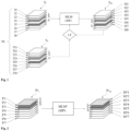
- Fig. 1 shows an exemplary and schematic embodiment of the computer-implemented method for training a machine learning model.
- the machine learning model MLM shown in Fig. 1 is trained on training data TD.
- the training data TD comprises, for each examination object of a plurality of examination objects, (i) input data and (ii) target data.
- This data set comprises one stack (S I ) of 2D images as input data, and one stack (S T ) of 2D target images as target data.
- Each stack (S I , S T ) represents the same 3D examination region of the examination object.
- the stack S I of the input data comprises a multitude of 2D images (I1, I2, I3, I4, I5, I6, I7, I8).
- Each image of the multitude of 2D images represents a slice of the 3D examination region of the examination object.
- the stack S T of the target data comprises a multitude of 2D target images (TI1, TI2, TI3, TI4, TI5, TI6, TI7, TI8).
- Each image of the multitude of 2D target images represents a slice of the 3D examination region of the examination object.
- the slices represented by the input images of the input data stack S I correspond to the slices represented by the target images of the target data stack S T .
- For each slice of the input data stack S I there is a corresponding slice of the target data stack S T and vice versa.
- "Correspond(s)" / "corresponding” means that the respective slices represent the same part of the 3D examination region, but preferably in a different state and/or at a different time and/or under different measurement conditions and/or as a result of a different measurement method and/or different measurement parameters.
- the slice represented by I1 corresponds with the slice represented by TI1
- the slice represented by I2 corresponds with the slice represented by TI2
- the slice represented by I3 corresponds with the slice represented by TI3
- the slice represented by I4 corresponds with the slice represented by TI4
- the slice represented by I5 corresponds with the slice represented by TI5
- the slice represented by I6 corresponds with the slice represented by TI6
- the slice represented by I7 corresponds with the slice represented by TI7
- the slice represented by I8 corresponds with the slice represented by TI8.
- I1 corresponds with TI1
- I2 corresponds with TI2
- I3 corresponds with TI3
- I4 corresponds with TI4
- I5 corresponds with TI5
- I6 corresponds with TI6
- I7 corresponds with TI7
- I8 corresponds with TI8.
- a first slice of the 3D examination region is selected at random (i.e., there is no particular order).
- the slice represented by the 2D image I3 in the stack S I of the input data and by the 2D target image TI3 in the stack S T of the target data is selected first.
- a 2D image (I3) is selected from the stack S I of the input data together with a corresponding 2D target image (TI3) from the stack S T of the target data.
- the 2D image I3 is inputted into machine learning model MLM.
- the machine learning model MLM is configured to generate a synthetic 2D image based on input data and parameters MP of the machine learning model MLM. So, the machine learning model MLM generates the synthetic 2D image SI3 based on the 2D image I3 and based on model parameters MP.
- the synthetic 2D image SI3 represents the same slice of the 3D examination region of the examination object as the 2D image I3 and the corresponding 2D target image TI3.
- the synthetic 2D image SI3 and the 2D target image TI3 are compared.
- a loss function LF is used to quantify deviations between the synthetic 2D image SI3 and the 2D target image TI3.
- Model parameters MP are modified in an optimization procedure to reduce the deviations.
- a second slice is selected.
- the second slice to be selected is the one represented by the 2D image I6 in the stack S I of the input data and by the 2D target image TI6 in the stack S T of the target data.
- a second 2D image (I6) from the stack (S I ) of the input data and a corresponding 2D target image (TI6) from the stack (S T ) of the target data are selected.
- the 2D image I6 is inputted into machine learning model MLM.
- the machine learning model MLM generates the synthetic 2D image SI6 based on the 2D image I6 and based on model parameters MP.
- the synthetic 2D image SI6 represents the same slice of the 3D examination region of the examination object as the 2D image I6 and the corresponding 2D target image TI6. In other words, SI6 corresponds with I6 and TI6.
- the synthetic 2D image SI6 and the corresponding 2D target image TI6 are compared.
- the loss function LF is used to quantify deviations between the synthetic 2D image SI6 and the 2D target image TI6.
- Model parameters MP are modified in the optimization procedure to reduce the deviations.
- a third slice is selected.
- the third slice to be selected is the one represented by the 2D image I4 in the stack S I of the input data and by the 2D target image TI4 in the stack S T of the target data.
- a third 2D image (I4) from the stack (S I ) of the input data and a corresponding 2D target image (TI4) from the stack (S T ) of the target data are selected.
- the 2D image I4 is inputted into machine learning model MLM.
- the machine learning model MLM generates the synthetic 2D image SI4 based on the 2D image I4 and based on model parameters MP.
- the synthetic 2D image SI4 represents the same slice of the 3D examination region of the examination object as the 2D image I4 and the corresponding 2D target image TI4. In other words, SI4 corresponds with I4 and TI4.
- the synthetic 2D image SI4 and the corresponding 2D target image TI4 are compared.
- the loss function LF is used to quantify deviations between the synthetic 2D image SI4 and the 2D target image TI4.
- Model parameters MP are modified in the optimization procedure to reduce the deviations.
- This process is continued, i.e. another slice is selected and the 2D image of the input data representing the selected slice is fed into the machine learning model MLM.
- further input data can be used to generate the synthetic 2D images in addition to the 2D images.
- the synthetic 2D image SI3 it is also possible to use one or more images adjacent to the 2D image I3 to generate the synthetic 2D image SI3, for example the 2D image I2 and/or the 2D image I4 and/or the 2D image I1 and/or the 2D image I5.
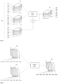
- the trained machine learning model can be used to generate one or more synthetic images of a new examination object. This is shown schematically as an example in Fig. 2 .
- Fig. 2 shows an exemplary and schematic embodiment of the computer-implemented method for generating one or more synthetic images using a trained machine learning model.
- the trained machine learning model MLM t shown in Fig. 2 may have been trained in a process described with respect to Fig. 1 .
- the trained machine learning model MLM 1 is fed with 2D images (I n 1, I n 2, I n 3, I n 4, I n 5, I n 6, I n 7) of a new examination object as input data.
- the 2D images I n 1, I n 2, I n 3, I n 4, I n 5, I n 6, I n 7 form a stack S n I .
- Each 2D image represents a slice in the examination region of the new examination object.
- the 2D images I n 1, I n 2, I n 3, I n 4, I n 5, I n 6, I n 7 are fed to the trained machine learning model MLM t one after the other in a pre-defined sequence (from top to bottom).
- Fig. 2 only shows the sequence of the 2D images I n 1, I n 2, I n 3. The other 2D images follow in the sequence I n 4, I n 5, I n 6, I n 7.
- the slice represented by the 2D image I n 2 is selected and the image I n 2 is fed to the trained machine learning model MLM t .
- the trained machine learning model MLM t generates the synthetic image SI n 2.
- the synthetic image SI n 2 represents the same slice of the examination region of the examination object as the image I n 2; I n 2 and SI n 2 correspond with each other.
- the synthetic 2D images can be output, e.g., individually and/or as the stack S n SI or in the form of a synthetic 3D image that can be generated based on the stack S n SI .
- one synthetic image is generated on the basis of one image.
- Fig. 3 shows another exemplary and schematic embodiment of the computer-implemented method for training a machine learning model.
- the machine learning model MLM shown in Fig. 3 is trained on training data TD.
- the training data TD comprises, for each examination object of a plurality of examination objects, (i) input data and (ii) target data.
- This data set comprises a (i) first stack (Sn) of 2D images and a second stack (S I2 ) of 2D images as input data, and (ii) a stack (S T ) of 2D target images as target data.
- Each stack (Sn, S I2 , S T ) represents the same 3D examination region of the examination object.
- the first stack S I1 of the input data comprises a number n of 2D images (I11, I12, I13, I14, I15, I16, ..., 11n). Each image of the multitude of 2D images represents a slice of the 3D examination region of the examination object.
- the second stack S I2 of the input data also comprises a number n of 2D images (I21, I22, I23, I24, I25, I26, ..., I2 n ).
- Each image of the multitude of 2D images represents a slice of the 3D examination region of the examination object.
- the stack S T of the target data comprises a number n of 2D target images (TI1, TI2, TI3, TI4, TI5, TI6, ..., TI n ).
- Each image of the multitude of 2D target images represents a slice of the 3D examination region of the examination object.
- the slices of the first input data stack S I , the slides of the second input data stack S 2 and the slices of the target data stack S T correspond with each other:
- the slice represented by I11 corresponds with the slice represented by I21 and with the slice represented by T1
- the slice represented by I12 corresponds with the slice represented by I22 and with the slice represented by TI2
- the slice represented by I13 corresponds with the slice represented by I23 and with the slice represented by TI3
- the slice represented by I14 corresponds with the slice represented by I24 and with the slice represented by TI4
- the slice represented by I15 corresponds with the slice represented by I25 and with the slice represented by TI5
- the slice represented by I16 corresponds with the slice represented by I26 and with the slice represented by TI6, ...
- the slice represented by I1 n corresponds with the slice represented by I2 n and with the slice represented by TI n .
- Corresponding slices represent the same part of the examination region of the examination object, but preferably in a different state and/or at a different time and/or under different measurement conditions and/or as a result of a different measurement method and/or different measurement parameters.
- I11 corresponds with I21 and T1
- I12 corresponds with I22 and TI2
- I13 corresponds with I23 and TI3
- I14 corresponds with I24 and TI4
- I15 corresponds with I25 and TI5
- I16 corresponds with I26 and TI6,
- I1 n corresponds with I2 n and TI n .
- Corresponding images represent the same slice of the examination region of the examination object, but preferably in a different state and/or at a different time and/or under different measurement conditions and/or as a result of a different measurement method and/or different measurement parameters.
- Corresponding images represent the same slice of the examination region of the examination object, but preferably in a different state and/or at a different time and/or under different measurement conditions and/or as a result of a different measurement method and/or different measurement parameters.
- a first slice of the 3D examination region is selected at random (i.e., slices are selected unordered).
- the slice represented by the 2D image I13 in the stack S I1 , by 2D image I23 in the stack S I2 , and by the 2D target image TI3 in the stack S T is selected first.
- All 2D images of the input data representing the selected slice are fed into the machine learning model MLM; in the example shown in Fig. 3 , these are the images I13 and I23.
- the machine learning model MLM is configured to generate a synthetic 2D image based on the input data and parameters MP of the machine learning model MLM. So, the machine learning model MLM generates the synthetic 2D image SI3 based on the 2D images I13 and I23 and based on model parameters MP.
- the synthetic 2D image SI3 represents the same slice of the 3D examination region of the examination object as the 2D images I13 and I23 and the corresponding 2D target image TI3.
- the synthetic 2D image SI3 and the 2D target image T3 are compared.
- a loss function LF is used to quantify deviations between the synthetic 2D image SI3 and the 2D target image TI3.
- Model parameters MP are modified in an optimization procedure to reduce the deviations.
- a second slice is selected at random. This is no longer shown in Fig. 3 .
- the further procedure is analogous to the procedure described in Fig. 1 , with the difference that a synthetic 2D image is based on two corresponding images of the input data instead of one.
- the number of corresponding 2D images on the basis of which a synthetic 2D image can be generated can be 3 or 4 or 5 or 6 or 7 or 8 or more than 8.
- the trained machine learning model can be used to generate one or more synthetic images of a new examination object. This is shown schematically as an example in Fig. 4 .
- Fig. 4 shows another exemplary and schematic embodiment of the computer-implemented method for generating one or more synthetic images using a trained machine learning model.
- the trained machine learning model MLM t shown in Fig. 4 may have been trained in a process described with respect to Fig. 3 .
- the slices and the 2D images representing the slices are arranged horizontally in the example shown in Fig. 3
- the slices and the 2D images representing them are arranged vertically in the example shown in Fig. 4 . This is to illustrate that the machine learning model of the present disclosure can be trained to process 2D images of differently arranged and oriented slices.
- the trained machine learning model MLM t is fed with 2D images of a new examination object as input data.
- the first stack S n I1 contains the 2D images I n 11, I n 12, I n 13, I n 14, I n 15, I n 16, ..., I n 1 n .
- the second stack S n I2 contains the 2D images I n 21, I n 22, I n 23, I n 24, I n 25, I n 26, ..., I n 2 n .
- I n 11 corresponds with I n
- I n 12 corresponds with I n
- F n 13 corresponds with I n
- F n 14 corresponds with I n
- I n 15 corresponds with I n
- I n 16 corresponds with I n 26
- I n 1 n corresponds with I n 2 n .
- Corresponding images represent the same slice of the examination region of the examination object, but preferably in a different state and/or at a different time and/or under different measurement conditions and/or as a result of a different measurement method and/or different measurement parameters.
- a first slice is selected.
- the slice selected first is the one represented by the 2D images I n 11 and I n 21.
- the 2D images I n 11 and I n 21 representing the selected slide are fed to the trained machine learning model MLM t .
- the trained machine learning model MLM t generates the synthetic 2D image SI n 1.
- the synthetic 2D image SI n 1 represents the same slice of the examination region of the examination object as the 2D images I n 11 and I n 21.
- SI n 1 corresponds I n 11 and I n 21.
- another slice can be selected and the 2D images representing the slice can be fed into the trained machine learning model to generate another synthetic 2D image that also represents the slice.
- the slices can be selected in a predefined order (e.g., from left to right).
- All generated synthetic 2D images can be output, stored and/or transmitted to a separate computer system individually and/or in the form of a stack (because, for example, in the form of the stack S n SI ) and/or in the form of a synthetic 3D image that can be generated based on the stack S n SI .
- Fig. 5 shows schematically in the form of a flow chart a preferred embodiment of the computer-implemented method for training the machine learning model of the present disclosure.
- the training method (100) comprises the steps.
- the inference method (200) comprises the steps.
- a “computer system” is an electronic data processing system that processes data by means of programmable calculation rules. Such a system typically comprises a “computer”, which is the unit that includes a processor for carrying out logic operations, and peripherals.
- peripherals refers to all devices that are connected to the computer and are used for control of the computer and/or as input and output devices. Examples thereof are monitor (screen), printer, scanner, mouse, keyboard, drives, camera, microphone, speakers, etc. Internal ports and expansion cards are also regarded as peripherals in computer technology.
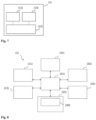
- the control and calculation unit (12) serves for control of the computer system (1), coordination of the data flows between the units of the computer system (1), and for the performance of calculations.
- One or more computer programs (40) may be stored in the storage medium (22) and executed by the processing unit (21), which is thereby programmed to fulfil the functions described in this description.
- the retrieving, loading and execution of instructions of the computer program (40) may take place sequentially, such that an instruction is respectively retrieved, loaded and executed. However, the retrieving, loading and/or execution may also take place in parallel.
Landscapes
- Engineering & Computer Science (AREA)
- Theoretical Computer Science (AREA)
- General Physics & Mathematics (AREA)
- Physics & Mathematics (AREA)
- Evolutionary Computation (AREA)
- Databases & Information Systems (AREA)
- Health & Medical Sciences (AREA)
- General Health & Medical Sciences (AREA)
- Medical Informatics (AREA)
- Software Systems (AREA)
- Computing Systems (AREA)
- Computer Vision & Pattern Recognition (AREA)
- Artificial Intelligence (AREA)
- Multimedia (AREA)
- Image Analysis (AREA)
Priority Applications (2)
| Application Number | Priority Date | Filing Date | Title |
|---|---|---|---|
| EP23217696.6A EP4575997A1 (fr) | 2023-12-18 | 2023-12-18 | Génération d'images synthétiques |
| US18/982,684 US20250200828A1 (en) | 2023-12-18 | 2024-12-16 | Generating synthetic images |
Applications Claiming Priority (1)
| Application Number | Priority Date | Filing Date | Title |
|---|---|---|---|
| EP23217696.6A EP4575997A1 (fr) | 2023-12-18 | 2023-12-18 | Génération d'images synthétiques |
Publications (1)
| Publication Number | Publication Date |
|---|---|
| EP4575997A1 true EP4575997A1 (fr) | 2025-06-25 |
Family
ID=89223626
Family Applications (1)
| Application Number | Title | Priority Date | Filing Date |
|---|---|---|---|
| EP23217696.6A Pending EP4575997A1 (fr) | 2023-12-18 | 2023-12-18 | Génération d'images synthétiques |
Country Status (2)
| Country | Link |
|---|---|
| US (1) | US20250200828A1 (fr) |
| EP (1) | EP4575997A1 (fr) |
Citations (12)
| Publication number | Priority date | Publication date | Assignee | Title |
|---|---|---|---|---|
| WO2014036473A1 (fr) | 2012-08-31 | 2014-03-06 | Kenji Suzuki | Technique d'apprentissage supervisée par machine servant à la réduction de la dose de rayonnement en imagerie tomographique par ordinateur |
| WO2016175755A1 (fr) | 2015-04-28 | 2016-11-03 | Siemens Healthcare Gmbh | Procédé et système pour synthétiser des images de tomographie calculée à dose élevée ou kv élevé virtuelles à partir d'images de tomographie calculée à faible dose ou faible kv |
| WO2018202541A1 (fr) | 2017-05-02 | 2018-11-08 | Bayer Aktiengesellschaft | Améliorations dans la détection radiologique de l'hypertension pulmonaire thromboembolique chronique |
| WO2019074938A1 (fr) | 2017-10-09 | 2019-04-18 | The Board Of Trustees Of The Leland Stanford Junior University | Réduction de dose de contraste pour imagerie médicale à l'aide d'un apprentissage profond |
| WO2020229152A1 (fr) | 2019-05-10 | 2020-11-19 | Bayer Consumer Care Ag | Identification de signes candidats indiquant une fusion oncogénique ntrk |
| WO2021052896A1 (fr) | 2019-09-18 | 2021-03-25 | Bayer Aktiengesellschaft | Prévision d'images irm au moyen d'un modèle de prévision entraîné par apprentissage supervisé |
| WO2021069338A1 (fr) | 2019-10-08 | 2021-04-15 | Bayer Aktiengesellschaft | Génération d'images irm du foie sans amélioration du contraste |
| WO2021197996A1 (fr) | 2020-04-03 | 2021-10-07 | Bayer Aktiengesellschaft | Génération d'images radiologiques |
| US11170543B2 (en) | 2020-01-13 | 2021-11-09 | The Board Of Trustees Of The Leland Stanford Junior University | MRI image reconstruction from undersampled data using adversarially trained generative neural network |
| US11181598B2 (en) | 2019-04-25 | 2021-11-23 | Siemens Healthcare Gmbh | Multi-contrast MRI image reconstruction using machine learning |
| WO2022184297A1 (fr) | 2021-03-02 | 2022-09-09 | Bayer Aktiengesellschaft | Apprentissage automatique dans le domaine de la radiologie avec injecton d'agent de contraste |
| WO2023073165A1 (fr) * | 2021-11-01 | 2023-05-04 | Bayer Aktiengesellschaft | Images rm synthétiques à contraste amélioré |
-
2023
- 2023-12-18 EP EP23217696.6A patent/EP4575997A1/fr active Pending
-
2024
- 2024-12-16 US US18/982,684 patent/US20250200828A1/en active Pending
Patent Citations (12)
| Publication number | Priority date | Publication date | Assignee | Title |
|---|---|---|---|---|
| WO2014036473A1 (fr) | 2012-08-31 | 2014-03-06 | Kenji Suzuki | Technique d'apprentissage supervisée par machine servant à la réduction de la dose de rayonnement en imagerie tomographique par ordinateur |
| WO2016175755A1 (fr) | 2015-04-28 | 2016-11-03 | Siemens Healthcare Gmbh | Procédé et système pour synthétiser des images de tomographie calculée à dose élevée ou kv élevé virtuelles à partir d'images de tomographie calculée à faible dose ou faible kv |
| WO2018202541A1 (fr) | 2017-05-02 | 2018-11-08 | Bayer Aktiengesellschaft | Améliorations dans la détection radiologique de l'hypertension pulmonaire thromboembolique chronique |
| WO2019074938A1 (fr) | 2017-10-09 | 2019-04-18 | The Board Of Trustees Of The Leland Stanford Junior University | Réduction de dose de contraste pour imagerie médicale à l'aide d'un apprentissage profond |
| US11181598B2 (en) | 2019-04-25 | 2021-11-23 | Siemens Healthcare Gmbh | Multi-contrast MRI image reconstruction using machine learning |
| WO2020229152A1 (fr) | 2019-05-10 | 2020-11-19 | Bayer Consumer Care Ag | Identification de signes candidats indiquant une fusion oncogénique ntrk |
| WO2021052896A1 (fr) | 2019-09-18 | 2021-03-25 | Bayer Aktiengesellschaft | Prévision d'images irm au moyen d'un modèle de prévision entraîné par apprentissage supervisé |
| WO2021069338A1 (fr) | 2019-10-08 | 2021-04-15 | Bayer Aktiengesellschaft | Génération d'images irm du foie sans amélioration du contraste |
| US11170543B2 (en) | 2020-01-13 | 2021-11-09 | The Board Of Trustees Of The Leland Stanford Junior University | MRI image reconstruction from undersampled data using adversarially trained generative neural network |
| WO2021197996A1 (fr) | 2020-04-03 | 2021-10-07 | Bayer Aktiengesellschaft | Génération d'images radiologiques |
| WO2022184297A1 (fr) | 2021-03-02 | 2022-09-09 | Bayer Aktiengesellschaft | Apprentissage automatique dans le domaine de la radiologie avec injecton d'agent de contraste |
| WO2023073165A1 (fr) * | 2021-11-01 | 2023-05-04 | Bayer Aktiengesellschaft | Images rm synthétiques à contraste amélioré |
Non-Patent Citations (13)
| Title |
|---|
| "ACR Manual on Contrast Media", 2020 |
| A. IGNEE ET AL.: "Ultrasound contrast agents", ENDOSC ULTRASOUND, vol. 5, no. 6, November 2016 (2016-11-01), pages 355 - 362 |
| A.S.L. JASCINTH ET AL.: "Contrast Agents in computed tomography: A Review", JOURNAL OF APPLIED DENTAL AND MEDICAL SCIENCES, vol. 2, 2016, pages 143 - 149 |
| H. LUSIC ET AL.: "X-ray-Computed Tomography Contrast Agents", CHEM. REV., vol. 113, no. 3, 2013, pages 1641 - 1666, XP055559399, Retrieved from the Internet <URL:https://www.radiology.wisc.edu/wp-content/uploads/2017/10/contrast-agents-tutorial.pdf> DOI: 10.1021/cr200358s |
| HAASE ROBERT ET AL: "Artificial Contrast : Deep Learning for Reducing Gadolinium-Based Contrast Agents in Neuroradiology", INVESTIGATIVE RADIOLOGY, vol. 58, no. 8, 1 August 2023 (2023-08-01), US, pages 539 - 547, XP093123607, ISSN: 0020-9996, DOI: 10.1097/RLI.0000000000000963 * |
| JUNHUA CHEN ET AL: "Improving Reproducibility and Performance of Radiomics in Low Dose CT using Cycle GANs", ARXIV.ORG, CORNELL UNIVERSITY LIBRARY, 201 OLIN LIBRARY CORNELL UNIVERSITY ITHACA, NY 14853, 16 September 2021 (2021-09-16), XP091056144 * |
| K. CATCH: "The Radon Transformation and Its Application in Tomography", JOURNAL OF PHYSICS CONFERENCE SERIES, no. 1, 1903, pages 012066 |
| L.C. ABONYI ET AL.: "Intravascular Contrast Media in Radiography: Historical Development & Review of Risk Factors for Adverse Reactions", SOUTH AMERICAN JOURNAL OF CLINICAL RESEARCH, vol. 3, 2016, pages 1 - 10 |
| M.R. NOUH ET AL.: "Radiographic and magnetic resonances contrast agents: Essentials and tips for safe practices", WORLD J RADIOL., vol. 9, no. 9, 28 September 2017 (2017-09-28), pages 339 - 349 |
| O. RONNEBERGER ET AL.: "t7 Net: Convolutional Networks for Biomedical Image Segmentation", ARXIV:1505.04597V1 |
| S. KHAN ET AL.: "Transformers in Vision: A Survey", ARXIV:2101.01169V5 |
| YANG HERAN ET AL: "Unsupervised MR-to-CT Synthesis Using Structure-Constrained CycleGAN", IEEE TRANSACTIONS ON MEDICAL IMAGING, IEEE, USA, vol. 39, no. 12, 10 August 2020 (2020-08-10), pages 4249 - 4261, XP011822949, ISSN: 0278-0062, [retrieved on 20201130], DOI: 10.1109/TMI.2020.3015379 * |
| Z. HUANG ET AL.: "Timescales of Intrinsic BOLD Signal Dynamics and Functional Connectivity in Pharmacologic and Neuropathologic States of Unconsciousness", THE JOURNAL OF NEUROSCIENCE, vol. 38, no. 9, 2018, pages 2304 - 2317 |
Also Published As
| Publication number | Publication date |
|---|---|
| US20250200828A1 (en) | 2025-06-19 |
Similar Documents
| Publication | Publication Date | Title |
|---|---|---|
| US12611152B2 (en) | Machine learning in the field of contrast-enhanced radiology | |
| US12008759B2 (en) | Method and system for identifying pathological changes in follow-up medical images | |
| CN111192316B (zh) | 用于动脉分析和评估的深度学习 | |
| US10699410B2 (en) | Automatic change detection in medical images | |
| US20200294288A1 (en) | Systems and methods of computed tomography image reconstruction | |
| Tmenova et al. | CycleGAN for style transfer in X-ray angiography | |
| CN107209945A (zh) | 使用机器学习的用于医学成像的转化的系统和方法 | |
| WO2022179896A2 (fr) | Approche acteur-critique pour la génération d'images de synthèse | |
| US20250191734A1 (en) | Generating synthetic images | |
| US20250201408A1 (en) | Prediction of representations of an examination area of an examination object after applications of different amounts of a contrast agent | |
| US20250201407A1 (en) | Prediction of a representation of an examination area of an examination object in a state of a sequence of states | |
| EP4210069A1 (fr) | Images tomodensitométriques synthétiques à contraste amélioré | |
| US20250292447A1 (en) | Generation of a synthetic medical image | |
| US20250200828A1 (en) | Generating synthetic images | |
| Waldkirch | Methods for three-dimensional registration of multimodal abdominal image data | |
| US20240404255A1 (en) | Generation of artificial contrast-enhanced radiological images | |
| EP4621717A1 (fr) | Génération d'une image médicale synthétique | |
| US20250378594A1 (en) | Generating synthetic representations | |
| Hachaj et al. | Nowadays and future computer application in medicine | |
| CN117063199A (zh) | 对比度增强放射学领域中的机器学习 | |
| WO2025219297A1 (fr) | Génération d'une image médicale synthétique | |
| WO2025221230A1 (fr) | Procédé de modélisation vasculaire 3d automatisé destiné à être utilisé dans le domaine médical | |
| Nakhawatchana et al. | A Segment Anything Model for Automated Intracranial Aneurysm Segmentation in Computed Tomography Angiography Images | |
| Varjo | Implementing A Texture Analysis Software Frame for Magnetic Resonance Image Data in Matlab | |
| CN117252940A (zh) | 重建医学影像的方法、装置及电子设备 |
Legal Events
| Date | Code | Title | Description |
|---|---|---|---|
| PUAI | Public reference made under article 153(3) epc to a published international application that has entered the european phase |
Free format text: ORIGINAL CODE: 0009012 |
|
| STAA | Information on the status of an ep patent application or granted ep patent |
Free format text: STATUS: THE APPLICATION HAS BEEN PUBLISHED |
|
| AK | Designated contracting states |
Kind code of ref document: A1 Designated state(s): AL AT BE BG CH CY CZ DE DK EE ES FI FR GB GR HR HU IE IS IT LI LT LU LV MC ME MK MT NL NO PL PT RO RS SE SI SK SM TR |
|
| STAA | Information on the status of an ep patent application or granted ep patent |
Free format text: STATUS: REQUEST FOR EXAMINATION WAS MADE |
|
| 17P | Request for examination filed |
Effective date: 20260102 |