EP4576018A1 - Procédé et appareil de traitement d'image - Google Patents
Procédé et appareil de traitement d'image Download PDFInfo
- Publication number
- EP4576018A1 EP4576018A1 EP23864498.3A EP23864498A EP4576018A1 EP 4576018 A1 EP4576018 A1 EP 4576018A1 EP 23864498 A EP23864498 A EP 23864498A EP 4576018 A1 EP4576018 A1 EP 4576018A1
- Authority
- EP
- European Patent Office
- Prior art keywords
- image
- isp
- raw
- parameter
- images
- Prior art date
- Legal status (The legal status is an assumption and is not a legal conclusion. Google has not performed a legal analysis and makes no representation as to the accuracy of the status listed.)
- Pending
Links
Images





Classifications
-
- G—PHYSICS
- G06—COMPUTING OR CALCULATING; COUNTING
- G06N—COMPUTING ARRANGEMENTS BASED ON SPECIFIC COMPUTATIONAL MODELS
- G06N3/00—Computing arrangements based on biological models
- G06N3/02—Neural networks
- G06N3/08—Learning methods
-
- G—PHYSICS
- G06—COMPUTING OR CALCULATING; COUNTING
- G06N—COMPUTING ARRANGEMENTS BASED ON SPECIFIC COMPUTATIONAL MODELS
- G06N3/00—Computing arrangements based on biological models
- G06N3/02—Neural networks
- G06N3/04—Architecture, e.g. interconnection topology
-
- G—PHYSICS
- G06—COMPUTING OR CALCULATING; COUNTING
- G06N—COMPUTING ARRANGEMENTS BASED ON SPECIFIC COMPUTATIONAL MODELS
- G06N3/00—Computing arrangements based on biological models
- G06N3/02—Neural networks
- G06N3/06—Physical realisation, i.e. hardware implementation of neural networks, neurons or parts of neurons
- G06N3/063—Physical realisation, i.e. hardware implementation of neural networks, neurons or parts of neurons using electronic means
-
- G—PHYSICS
- G06—COMPUTING OR CALCULATING; COUNTING
- G06T—IMAGE DATA PROCESSING OR GENERATION, IN GENERAL
- G06T5/00—Image enhancement or restoration
- G06T5/60—Image enhancement or restoration using machine learning, e.g. neural networks
-
- G—PHYSICS
- G06—COMPUTING OR CALCULATING; COUNTING
- G06V—IMAGE OR VIDEO RECOGNITION OR UNDERSTANDING
- G06V10/00—Arrangements for image or video recognition or understanding
- G06V10/20—Image preprocessing
-
- G—PHYSICS
- G06—COMPUTING OR CALCULATING; COUNTING
- G06V—IMAGE OR VIDEO RECOGNITION OR UNDERSTANDING
- G06V10/00—Arrangements for image or video recognition or understanding
- G06V10/70—Arrangements for image or video recognition or understanding using pattern recognition or machine learning
- G06V10/82—Arrangements for image or video recognition or understanding using pattern recognition or machine learning using neural networks
-
- H—ELECTRICITY
- H04—ELECTRIC COMMUNICATION TECHNIQUE
- H04N—PICTORIAL COMMUNICATION, e.g. TELEVISION
- H04N23/00—Cameras or camera modules comprising electronic image sensors; Control thereof
- H04N23/80—Camera processing pipelines; Components thereof
-
- G—PHYSICS
- G06—COMPUTING OR CALCULATING; COUNTING
- G06T—IMAGE DATA PROCESSING OR GENERATION, IN GENERAL
- G06T2207/00—Indexing scheme for image analysis or image enhancement
- G06T2207/20—Special algorithmic details
- G06T2207/20081—Training; Learning
-
- G—PHYSICS
- G06—COMPUTING OR CALCULATING; COUNTING
- G06T—IMAGE DATA PROCESSING OR GENERATION, IN GENERAL
- G06T2207/00—Indexing scheme for image analysis or image enhancement
- G06T2207/20—Special algorithmic details
- G06T2207/20084—Artificial neural networks [ANN]
Definitions
- Embodiments of this application provide an image processing method and apparatus.
- the apparatus may generate, based on raw images obtained in different scenarios, ISP parameters that satisfy a corresponding scenario, to dynamically adjust the ISP parameters, so as to perform adaptive image enhancement for the different scenarios.
- an embodiment of this application provides an image processing method.
- the method includes: An apparatus obtains a first raw image captured by a camera in a first scenario.
- the apparatus obtains a first ISP parameter based on the first raw image.
- the apparatus performs, based on the first ISP parameter, image processing on the first raw image captured by the camera, to obtain a first image.
- the apparatus outputs the first image to a target application, to enable the target application to perform image task processing on the first image.
- the apparatus obtains a second raw image captured by the camera in a second scenario.
- the apparatus obtains a second ISP parameter based on the second raw image.
- the apparatus performs, based on the second ISP parameter, image processing on the second raw image captured by the camera, to obtain a second image.
- the apparatus may periodically obtain the ISP parameter, to reduce computing pressure of the apparatus.
- the target application may be a perception application or a display application. This is not limited in this application.
- an image processing task of a CV perception application may include but is not limited to 2D/3D target detection, lane line detection, and scenario semantic segmentation. This is not limited in this application.
- image content of the first raw image is different from that of the second raw image, and/or an image attribute of the first raw image is different from that of the second raw image.
- images photographed in the different scenarios have different content and/or attributes.
- corresponding ISP parameters may be predicted based on different raw images, to obtain a better image processing result, so as to adapt to different scenario requirements.
- the first ISP parameter and the second ISP parameter are used for adjusting at least one of the following image attributes of an image: brightness, a color, noise, sharpness, and contrast.
- different ISP parameters may be used for adjusting different image attributes, to achieve better image effects.
- the image attributes of the first image and the second image satisfy an image task requirement of the target application.
- the image processing is intended to satisfy a requirement of the target application, so that the target application can better recognize an image obtained through the processing, to improve accuracy of image recognition (or another image processing procedure) of the target application.
- the obtaining a first ISP parameter based on the first raw image includes: inputting the first raw image to an ISP parameter prediction model to obtain the first ISP parameter that is predicted by the ISP parameter prediction model based on the first raw image.
- the obtaining a second ISP parameter based on the second raw image includes: inputting the second raw image to the ISP parameter prediction model to obtain the second ISP parameter that is predicted by the ISP parameter prediction model based on the second raw image.
- the ISP parameter prediction model runs on a neural-network processing unit NPU.
- running of the prediction model occupies general computing power of the NPU, and only a small computing amount is needed.
- the prediction model can be deployed on an edge device, and a high-priority task on an AI processor is not occupied.
- the method before the obtaining a first raw image captured by a camera in a first scenario, the method further includes: obtaining the ISP parameter prediction model from a cloud.
- a product in circulation in the market can be supported in an over-the-air download update manner (that is, obtained from the cloud and installed) to satisfy a compatibility requirement, provided that for the apparatus, an ISP system of a chip on sale supports dynamic refreshing and writing of a parameter.
- the performing image processing on the first raw image based on the first ISP parameter, to obtain a first image includes: replacing an ISP parameter currently stored in an ISP internal memory with the first ISP parameter, to enable an ISP to obtain the first ISP parameter from the ISP internal memory, and performing image processing on the first raw image based on the first ISP parameter, to output the first image.
- the performing image processing on the second raw image based on the second ISP parameter, to obtain a second image includes: replacing the first ISP parameter currently stored in the ISP internal memory with the second ISP parameter, to enable the ISP to obtain the second ISP parameter from the ISP internal memory, and performing image processing on the second raw image based on the second ISP parameter, to output the second image.
- an embodiment of this application provides a model training method.
- the method includes: inputting N raw images to an image signal processor ISP parameter prediction model to obtain N ISP parameters that are output by the ISP parameter prediction model, where a weight of the ISP parameter prediction model is a first weight, the N ISP parameters are obtained by the ISP parameter prediction model based on the first weight, and N is an integer greater than 1; inputting the N ISP parameters and the N raw images to a proxy model to obtain N images that are output by the proxy model; inputting the N images to a target application to obtain an image task processing result that is output by the target application; and if the image task processing result does not satisfy a preset condition, adjusting the weight of the ISP parameter prediction model to a second weight, and starting the procedure again from the step of inputting N raw images to an ISP parameter prediction model, until the image task processing result that is output by the target application satisfies the preset condition.
- a proxy network can implement a function of an ISP, and implement
- the model training method may be performed on a computing node.
- the preset condition includes: a difference value between a preset truth label of the N raw images and a truth label included in the image task processing result of the target application is less than a preset threshold.
- the method before the inputting N raw images to an ISP parameter prediction model, the method further includes: inputting M raw images and M ISP parameters to an ISP to obtain M images that are output by the image processor, where the M raw images are in one-to-one correspondence with the M ISP parameters, and M is an integer greater than 1; inputting the M raw images and the M ISP parameters to the proxy model to obtain M images that are output by the proxy model, where a current weight of the proxy model is a third weight; and if a similarity between the M images that are output by the proxy model and the M images that are output by the image processor is less than a threshold, adjusting the weight of the proxy model to a fourth weight, and starting the procedure again from the step of inputting M raw images and M ISP parameters to an ISP, until the similarity between the M images that are output by the proxy model and the M images that are output by the image processor is greater than the threshold.
- the proxy network is trained, so that a processing result of the proxy network may approximate or be the
- an embodiment of this application provides an image processing apparatus.
- the apparatus includes an ISP parameter prediction module and an ISP module.
- the ISP parameter prediction module is configured to obtain a first raw image captured by a camera in a first scenario.
- the ISP parameter prediction module is further configured to obtain a first image signal processor ISP parameter based on the first raw image.
- the image processing ISP module is configured to perform image processing on the first raw image based on the first ISP parameter, to obtain a first image.
- the ISP module is further configured to output the first image to a target application, to enable the target application to perform image task processing on the first image.
- the ISP parameter prediction module is further configured to obtain a second raw image captured by the camera in a second scenario.
- the ISP parameter prediction module is further configured to obtain a second ISP parameter based on the second raw image.
- the ISP module is further configured to perform image processing on the second raw image based on the second ISP parameter, to obtain a second image.
- the ISP module is further configured to output the second image to the target application, to enable the target application to perform image task processing on the second image.
- image content of the first raw image is different from that of the second raw image, and/or an image attribute of the first raw image is different from that of the second raw image.
- the first ISP parameter and the second ISP parameter are used for adjusting at least one of the following image attributes of an image: brightness, a color, noise, sharpness, and contrast.
- the image attributes of the first image and the second image satisfy an image task requirement of the target application.
- an embodiment of this application provides a model training system.
- the model training system includes an image signal processor ISP parameter prediction model, a proxy model, and a target application.
- the system inputs N raw images to the ISP parameter prediction model to obtain N ISP parameters that are output by the ISP parameter prediction model, where a weight of the ISP parameter prediction model is a first weight, the N ISP parameters are obtained by the ISP parameter prediction model based on the first weight, and N is an integer greater than 1.
- the system inputs the N ISP parameters and the N raw images to the proxy model to obtain N images that are output by the proxy model.
- the system inputs the N images to the target application.
- the UART interface is a universal serial data bus and is used for asynchronous communication.
- the bus may be a bidirectional communication bus.
- the bus converts to-be-transmitted data between serial communication and parallel communication.
- the UART interface is usually configured to connect the processor 110 to the wireless communication module 160.
- the processor 110 communicates with a Bluetooth module in the wireless communication module 160 through the UART interface, to implement a Bluetooth function.
- the audio module 170 may transmit an audio signal to the wireless communication module 160 through the UART interface, to implement a function of playing music via a Bluetooth headset.
- the GPIO interface may be configured by software.
- the GPIO interface may be configured as a control signal interface or a data signal interface.
- the GPIO interface may be configured to connect the processor 110 to the camera 193, the display screen 194, the wireless communication module 160, the audio module 170, the sensor module 180, or the like.
- the GPIO interface may alternatively be configured as an I2C interface, an I2S interface, a UART interface, an MIPI interface, or the like.
- the USB interface 130 is an interface that conforms to a USB standard specification, and may be specifically a mini USB interface, a micro USB interface, a USB Type-C interface, or the like.
- the USB interface 130 may be configured to be connected to a charger to charge the electronic device 100, or may be configured to transmit data between the electronic device 100 and a peripheral device, or may be configured to be connected to a headset for playing audio via the headset.
- the interface may be further configured to be connected to another electronic device, for example, an AR device.
- an interface connection relationship between modules illustrated in this embodiment of this application is merely an illustrative description, and does not constitute a limitation on the structure of the electronic device 100.
- the electronic device 100 may alternatively use an interface connection manner different from that in the foregoing embodiment, or use a combination of a plurality of interface connection manners.
- the charging management module 140 is configured to receive a charging input from the charger.
- the charger may be a wireless charger or a wired charger.
- the charging management module 140 may receive a charging input of a wired charger through the USB interface 130.
- the charging management module 140 may receive a wireless charging input through a wireless charging coil of the electronic device 100.
- the charging management module 140 supplies power to the electronic device through the power management module 141 while charging the battery 142.
- the antenna 1 and the antenna 2 are configured to transmit and receive an electromagnetic wave signal.
- Each antenna in the electronic device 100 may be configured to cover one or more communication frequency bands. Different antennas may be further reused, to improve antenna utilization.
- the antenna 1 may be reused as a diversity antenna of a wireless local area network.
- the antenna may be used together with a tuning switch.
- the antenna 1 is coupled to the mobile communication module 150, and the antenna 2 is coupled to the wireless communication module 160, so that the electronic device 100 can communicate with a network and another device by using a wireless communication technology.
- the wireless communication technology may include a global system for mobile communications (global system for mobile communications, GSM) technology, a general packet radio service (general packet radio service, GPRS) technology, a code division multiple access (code division multiple access, CDMA) technology, a wideband code division multiple access (wideband code division multiple access, WCDMA) technology, a time-division code division multiple access (time-division code division multiple access, TD-SCDMA) technology, a long term evolution (long term evolution, LTE) technology, a BT technology, a GNSS technology, a WLAN technology, an NFC technology, an FM technology, an IR technology, and/or the like.
- GSM global system for mobile communications
- GPRS general packet radio service
- CDMA code division multiple access
- WCDMA wideband code division multiple access
- the GNSS may include a global positioning system (global positioning system, GPS), a global navigation satellite system (global navigation satellite system, GLONASS), a BeiDou navigation satellite system (BeiDou navigation satellite system, BDS), a quasi-zenith satellite system (quasi-zenith satellite system, QZSS), and/or a satellite based augmentation system (satellite based augmentation system, SBAS).
- GPS global positioning system
- GLONASS global navigation satellite system
- BeiDou navigation satellite system BeiDou navigation satellite system
- BDS BeiDou navigation satellite system
- QZSS quasi-zenith satellite system
- SBAS satellite based augmentation system
- the electronic device 100 may implement a display function through the GPU, the display screen 194, the application processor, and the like.
- the GPU is a microprocessor for image processing, and is connected to the display screen 194 and the application processor.
- the GPU is configured to perform mathematical and geometric calculations for graphics rendering.
- the processor 110 may include one or more GPUs that execute program instructions to generate or change display information.
- the display screen 194 is configured to display an image, a video, and the like.
- the display screen 194 includes a display panel.
- the display panel may be a liquid crystal display (liquid crystal display, LCD), an organic light-emitting diode (organic light-emitting diode, OLED), an active-matrix organic light-emitting diode (active-matrix organic light-emitting diode, AMOLED), a flexible light-emitting diode (flexible light-emitting diode, FLED), a mini-LED, a micro-LED, a micro-OLED, a quantum dot light-emitting diode (quantum dot light-emitting diode, QLED), or the like.
- the electronic device 100 may include one or N display screens 194, where N is a positive integer greater than 1.
- the electronic device 100 may implement a photographing function through the ISP, the camera 193, the video codec, the GPU, the display screen 194, the application processor, and the like.
- the ISP is configured to process data fed back by the camera 193. For example, during photographing, a shutter is turned on, and light is transmitted to a photosensitive element of the camera through a lens. An optical signal is converted into an electrical signal, and the electrical signal is processed by the ISP and is converted into an image visible to naked eyes.
- the ISP may further perform algorithm optimization on image attributes such as noise, brightness, white balance, and contrast.
- the ISP may be disposed in the camera 193.
- attributes of ISPs optimized by different vendors and different models may be set based on an actual requirement. For example, an ISP of an electronic device A may optimize noise and brightness of an image, and an ISP of an electronic device B may optimize brightness and contrast of an image. This is not limited in this application.
- the camera 193 is configured to capture a static image or a video. An optical image of an object is generated through the lens and is projected onto the photosensitive element.
- the photosensitive element may be a charge-coupled device (charge-coupled device, CCD) or a complementary metal-oxide-semiconductor (complementary metal-oxide-semiconductor, CMOS) phototransistor.
- the electronic device 100 may include one or N cameras 193, where N is a positive integer greater than 1.
- an image captured by the camera 193 may be referred to as a raw image (or a raw image for short), and may be understood as a raw image file.
- the ISP may perform image processing on the raw image and output an RGB image or a YUV image.
- RGB and YUV are color spaces and are used for representing colors.
- "Y” indicates brightness, that is, a gray-scale value
- "U” and "V” indicate a color and saturation of an image and are used for specifying a color of a pixel.
- An RGB color model is a color standard in the industry, and various colors are obtained by changing red (R), green (G), and blue (B) color channels and superimposing the three colors on each other.
- the video codec is configured to compress or decompress a digital video.
- the electronic device 100 may support one or more video codecs. In this way, the electronic device 100 may play or record videos in a plurality of encoding formats, for example, moving picture experts group (moving picture experts group, MPEG) 1, MPEG 2, MPEG 3, and MPEG 4.
- MPEG moving picture experts group
- the NPU is a neural network (neural network, NN) computing processor. Based on a structure of a biological neural network, for example, a transmission mode between neurons in a human brain, the NPU quickly processes input information and can further continuously perform self-learning. Applications such as intelligent cognition of the electronic device 100 may be implemented through the NPU, for example, image recognition, facial recognition, voice recognition, and text understanding.
- the NPU may be configured to support an FW parameter prediction network in an FW parameter setting module. In other words, the NPU performs steps performed by the FW parameter prediction network in the FW parameter setting module.
- the speaker 170A also referred to as a "loudspeaker" is configured to convert an electrical audio signal into a sound signal.
- the electronic device 100 may be configured to listen to music or make/answer a call in a hands-free mode by using the speaker 170A.
- the fingerprint sensor 180H is configured to collect a fingerprint.
- the electronic device 100 may use a feature of the collected fingerprint to implement fingerprint-based unlocking, application lock access, fingerprint-based photographing, fingerprint-based call answering, and the like.
- the view system includes visual controls, for example, a control for text display and a control for image display.
- the view system may be configured to construct an application program.
- a display interface may include one or more views.
- a display interface including an SMS message notification icon may include a text display view and an image display view.
- the phone manager is configured to provide a communication function for the electronic device 100, for example, management of a call status (including connected, hang-up, and the like).
- the computing node (which may be specifically a CPU of the computing node) obtains the N RGB_ISP images that are output by the ISP and the N RGB_DL images that are output by the proxy network.
- the computing node may obtain a similarity between two corresponding images based on correspondences between the N RGB_ISP images and the N RGB_DL images, to obtain N similarities.
- the computing node may obtain, based on the N similarities, an overall similarity between the RGB_ISP image obtained through processing by the ISP and the RGB_DL image obtained through processing by the proxy network.
- each image is an array.
- the RGB_ISP image 1 and the RGB_DL image 1 are used as an example.
- the RGB_ISP image 1 is denoted as I out_ISP
- the RGB_DL image 1 is denoted as I out_DL
- the raw image 1 is denoted as I Raw
- the FW parameter is p.
- the computing node calculates a difference value (which may also be referred to as an error, a similarity difference value, or the like, where this is not limited in this application) between I out_ISP and I out_DL , and the difference value is denoted as L_1.
- a difference value which may also be referred to as an error, a similarity difference value, or the like, where this is not limited in this application
- L_1 the difference value
- the computing node may obtain, based on the foregoing manner, similarity difference values between each pair of the N RGB_ISP images and the N RGB_DL images, to obtain N similarity difference values, for example, L_1, ..., and L_N.
- the computing node calculates an average value of the N similarity difference values, that is, a similarity value between the RGB_ISP image obtained through processing by the ISP and the RGB_DL image obtained through processing by the proxy network, and the average value is denoted as L.
- a similarity value may alternatively be calculated in a calculation manner, for example, arithmetic averaging. This is not limited in this application.
- S704 is performed if the computing node detects that an L value is less than the threshold, which may also be understood as that the similarity is greater than the threshold.
- the computing node may store a current proxy network weight, and lock the proxy network weight, to avoid a change of the proxy network weight with subsequent processing.
- the proxy network weight needs to be adjusted again, so that the proxy network performs S702 again based on a new weight.
- the computing node calculates a corresponding gradient value based on the current proxy network weight (denoted as w t ) by using an optimization algorithm, for example, a gradient descent algorithm, and performs gradient descent update on the current proxy network weight ( w t ) based on the gradient value, to obtain an updated proxy network weight that is denoted as w t +1 .
- an optimization algorithm for example, a gradient descent algorithm
- w t a gradient descent algorithm
- the proxy network may perform S702 again.
- the proxy network processes the training FW parameter and the training raw image based on the updated weight ( w t +1 ).
- the computing node may compare the output result of the proxy network with an output result (S701 needs to be performed only once) of the ISP again, and perform S704 or S705 based on a comparison result.
- a quantity of cycles depends on the L value in S703, that is, a similarity between images of the output result of the proxy network and the output result of the ISP.
- the computing node detects that a similarity is greater than the threshold, in other words, the L value is less than the threshold, the proxy network weight is stored, and the training ends.
- the FW parameter prediction network is a deep network deployed on an AI processor.
- the FW parameter prediction network reads, on demand from a storage (for example, a DDR), to-be-processed raw image data in a video stream captured by a current camera, and performs optimal FW parameter prediction (which may also be understood as network inference).
- the FW parameter prediction network writes predicted parameters (a group of vectors whose length is N, where N is a quantity of FW parameters that may be dynamically configured) into a shared memory of ISP firmware to overwrite original FW parameters.
- training the FW parameter prediction network may be understood as a process of making an output result of the FW parameter prediction network gradually accurate.
- the FW parameter prediction network is the same as the proxy network, and an initial weight is also set for the FW parameter prediction network.
- the FW parameter prediction network weight is continuously updated in the process, so that the output result of the FW parameter prediction network is gradually optimized.
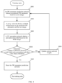
- FIG. 8 is a schematic flowchart of an example of FW parameter prediction network training. Refer to FIG. 8 .
- a training procedure specifically includes but is not limited to the following steps.
- the FW parameter prediction network obtains a predicted FW parameter based on a raw image.
- the computing node may input N raw images (that is, the N raw images in the preparation phase) to the FW parameter prediction network, and the FW parameter prediction network may process (or perform an operation on) the input N raw images based on a current weight (which may be the initial weight or an updated weight), to obtain N predicted FW parameters.
- N raw images that is, the N raw images in the preparation phase
- the FW parameter prediction network may process (or perform an operation on) the input N raw images based on a current weight (which may be the initial weight or an updated weight), to obtain N predicted FW parameters.
- a current weight which may be the initial weight or an updated weight
- an input sample in the FW parameter prediction network training phase that is, the N raw images
- the input sample in the FW parameter prediction network training phase may be M images in the N raw images.
- the input sample in the FW parameter prediction network training phase may alternatively be other M raw images different from those in the proxy network training phase. This is not limited in this application.
- the computing node may input the N raw images to the FW parameter prediction network in batches based on a processing capability of the FW parameter prediction network.
- the quantity of raw images that are input each time may be the same or different.
- the computing node may input 20 raw images to the FW parameter prediction network each time.
- the value is merely an example, and may be set based on an actual requirement. This is not limited in this application.
- the N predicted FW parameters that are output by the FW parameter prediction network are in one-to-one correspondence with the input raw images.
- the FW parameter prediction network may output a predicted FW parameter 1 based on a raw image 1, and output a predicted FW parameter 2 based on a raw image 2.
- the initial weight is set for the FW parameter prediction network, and the initial weight is randomly set by an operator.
- the result that is, an array
- the result that is output by the FW parameter prediction network is still referred to as the predicted FW parameter.
- the procedure shown in FIG. 8 may be understood as continuously training the FW parameter prediction network, to update the FW parameter prediction network weight, and continuously optimize the result that is output by the FW parameter prediction network.
- the proxy network obtains an RGB image based on the predicted FW parameter and the raw image.
- the proxy network may process (or perform an operation on) the N raw images based on a current weight (that is, the weight obtained through training in FIG. 7 ) and the correspondences between the N raw images and the N predicted FW parameters, to obtain N RGB images.
- the proxy network may process (or perform an operation on) the predicted FW parameter 1 and the raw image 1 as a pair of input parameters based on the current weight and a correspondence between the raw image 1 and the predicted FW parameter 1 (to be specific, the predicted FW parameter 1 is obtained by the FW parameter prediction network based on the raw image 1), to obtain an RGB image 1.
- the computing node may obtain a correspondence between the raw image 1, the predicted FW parameter 1, and the RGB image 1.
- the proxy network has been trained in FIG. 7 , and the result (that is, an RGB image) obtained by processing the raw image by the proxy network based on the current weight is the same as or approximate (that is, similar to) a result obtained through processing by an ISP of a specified model.
- the proxy network may be considered as an ISP, to perform image processing on the raw image to obtain a corresponding RGB image.
- the proxy network has the differentiability to implement end-to-end joint training between the FW parameter prediction network and the CV perception network.
- the CV perception network obtains a perception task label based on the RGB image.
- a function of the CV perception network may be to output a corresponding perception task label based on an input raw image.
- a quantity and types of perception task labels depend on a task type of the CV perception network. For example, if the task type of the CV perception network is an object recognition type, the CV perception network may output a corresponding perception task label based on the input raw image, and the perception task label includes an object type label.
- the computing node may input the N RGB images (which may be input in batches, where for a specific processing manner, refer to the foregoing descriptions, and details are not described herein again) to the CV perception network.
- the CV perception network may process (or recognize) the N RGB images to obtain N perception task labels.
- the N RGB images are in one-to-one correspondence with the N perception task labels.
- each perception task label may include a plurality of subtask labels, and types and a quantity of subtask labels are associated with the task type of the CV perception network. For detailed descriptions, refer to the foregoing descriptions. Details are not described herein again.
- the computing node may obtain correspondences between the N RGB images and the N perception task labels.
- the computing node further obtains correspondences between the N RGB images and the N raw images.
- the computing node may obtain correspondences between the N perception task labels and the N raw images. For example, a perception task label 1 corresponds to the raw image 1, and a perception task label 2 corresponds to the raw image 2.
- the computing node may obtain the correspondences (the correspondences are one-to-one correspondences) between the N perception task labels and the N truth labels based on the correspondences between the N perception task labels and the N raw images and the correspondences between the N truth labels and the N raw images.
- the perception task label 1 corresponds to a truth label 1
- the perception task label 2 corresponds to a truth label 2.
- S804 Determine whether a difference between the truth label and the perception task label is less than a threshold.
- the computing node may obtain the correspondences between the N perception task labels and the N truth labels.
- the computing node may obtain, based on the correspondences between the N perception task labels and the N truth labels, a difference value (which may also be referred to as a difference value, a loss function, or the like, where this is not limited in this application) between a corresponding pair of a perception task label and a truth label, to obtain the N difference values.
- a difference value which may also be referred to as a difference value, a loss function, or the like, where this is not limited in this application
- the computing node obtains the difference value between the truth label and the perception task label refer to embodiments of conventional technologies. This is not limited in this application.
- the computing node may obtain an average value (which may alternatively be an arithmetic average, where this is not limited in this application) of the N difference values, and the average value is denoted as Q.
- an average value (which may alternatively be an arithmetic average, where this is not limited in this application) of the N difference values, and the average value is denoted as Q.
- the computing node detects whether Q is greater than (or equal to) a preset threshold.
- the preset threshold may be set based on an actual requirement. This is not limited in this application.
- the preset threshold indicates a difference between two labels. A smaller preset threshold indicates a smaller difference between the two labels. Correspondingly, a smaller Q value indicates a smaller difference between the two labels.
- the computing node detects that the Q value is less than the threshold, which may also be understood as that the difference is less than the threshold, S704 is performed.
- the computing node detects that the Q value is greater than or equal to the threshold, and this may also be understood as that the difference is greater than the threshold.
- the difference between the perception task label output by the CV perception network based on the RGB image output by the proxy network and the truth label is large, and this may also be understood as that an enhancement effect of the RGB image obtained by the proxy network based on the predicted FW parameter is poor, resulting in an inaccurate result recognized by the CV perception network.
- This may also be understood as that correction on the raw image by the predicted FW parameter cannot achieve an enhancement effect that can be recognized by the CV perception network.
- the computing node performs S806.
- the computing node may store the FW parameter prediction network, to be specific, store a current structure (for example, a neural network structure) of the FW parameter prediction network and the current FW parameter prediction network weight that is denoted as w f .
- the FW parameter prediction network weight needs to be adjusted again, so that the FW parameter prediction network performs S801 again based on an updated weight.
- the computing node calculates a corresponding gradient value based on the current FW parameter prediction network weight ( w f ) by using an optimization algorithm (which may be set based on an actual requirement, where this is not limited in this application), for example, a gradient descent algorithm, and performs gradient descent update on the current FW parameter prediction network weight ( w f ) based on the gradient value, to obtain an updated FW parameter prediction network weight that is denoted as w f +1 .
- an optimization algorithm which may be set based on an actual requirement, where this is not limited in this application
- a gradient descent algorithm performs gradient descent update on the current FW parameter prediction network weight ( w f ) based on the gradient value, to obtain an updated FW parameter prediction network weight that is denoted as w f +1 .
- the FW parameter prediction network may perform S801 again.
- the FW parameter prediction network processes the raw image based on the updated weight (w f +1 ), to obtain the corresponding predicted FW parameter.
- a quantity of cycles of the procedure in FIG. 8 depends on the Q value in S804, that is, the difference between the perception task label and the truth label. In any cycle, if the value Q is less than the threshold, the computing node stores the FW parameter prediction network and the corresponding FW parameter prediction network weight, and the training ends.
- FIG. 9 is a diagram of an example of a system structure of FW parameter prediction network training.
- the computing node inputs a raw image to the FW parameter prediction network.
- the FW parameter prediction network outputs a predicted FW parameter based on the input raw image.
- the predicted FW parameter and the raw image are used as inputs of the proxy network, and the proxy network outputs an RGB image.
- the RGB image is used as an input of the CV perception network, and the computing node may obtain a Q value (that is, a difference value or a loss function) based on an output of the CV perception network.
- a Q value that is, a difference value or a loss function
- the image processing method further includes the online deployment phase.
- the FW parameter prediction network and the weight of the FW parameter prediction network that are stored in FIG. 8 are deployed in the target device.
- the target device is a device corresponding to the ISP in the training process.
- the ISP is the electronic device of the model A
- the operator may deploy the FW parameter prediction network and the weight of the FW parameter prediction network that are stored by the computing node on the electronic device of the model A.
- the electronic device of the model A may alternatively obtain and install the FW parameter prediction network and the weight of the FW parameter prediction network by using the cloud. This is not limited in this application.
- the target device loads the FW parameter prediction network and the weight of the FW parameter prediction network to the internal memory.
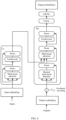
- An FW parameter prediction task works in an operating system as a resident process of the AI processor (for example, an NPU), and may also be understood as the FW parameter setting module (which may also be referred to as an FW parameter prediction module) in FIG. 2 or an FW parameter setting (prediction) application running at the application layer.
- the self-driving application may recognize the RGB image based on a CV perception network of the application, to obtain a recognition result, and perform a self-driving operation based on the recognition result.
- the FW parameter prediction network in the FW parameter setting module may predict each frame of raw image captured by the camera, in other words, perform the procedure in FIG. 10 for each raw image.
- the FW parameter prediction network in the FW parameter setting module may predict, based on a preset periodicity (which, for example, may be set based on interval duration, or may be set based on a frame rate of the image captured by the camera, or may be set based on an actual requirement, where this is not limited in this application), the raw image captured by the camera.
- the FW parameter setting module may perform prediction once every 1s, to reduce a workload of the AI processor.
- the FW parameter setting module may work in a sleep mode after being invoked by the application, and perform prediction only once when an application layer sends a wake-up signal to the FW parameter setting module.
- the self-driving application may send indication information to the FW parameter setting module only when a CPU (for example, the self-driving application) detects a significant change (for example, entering or leaving a tunnel or a garage, or day/night alternation) in a driving environment, to trigger the FW parameter setting module to perform FW parameter prediction, where the parameter prediction may be performed only once.
- the FW parameter setting module may alternatively be triggered after the electronic device is started.
- an input of the FW parameter setting module may be a raw image with low resolution after downsampling.
- a downsampling operation may be performed by the AI processor, or may be performed by the ISP HW.
- the ISP HW may obtain the raw image from the shared memory, perform downsampling on the raw image, and output the raw image with low resolution to the shared memory.
- the FW parameter setting module may read the raw image with low resolution from the shared memory and perform subsequent processing.
- the raw image read by the FW parameter setting module from the shared memory may alternatively be obtained through processing on the original raw image by other encoding or compression modules. This is not limited in this application.
- FIG. 11 is a block diagram of an apparatus 1100 according to an embodiment of this application.
- the apparatus 1100 may include a processor 1101 and a transceiver/transceiver pin 1102.
- the apparatus 1100 further includes a memory 1103.
- the bus 1104 further includes a power bus, a control bus, and a status signal bus.
- various buses in the figure are referred to as the bus 1104.
- the memory 1103 may be configured to store instructions in the foregoing method embodiments.
- the processor 1101 may be configured to: execute the instructions in the memory 1103, control a receive pin to receive a signal, and control a transmit pin to send a signal.
- the apparatus 1100 may be the electronic device in the foregoing method embodiments, a camera module, or a chip of the electronic device.
- An embodiment further provides a computer storage medium.
- the computer storage medium stores computer instructions.
- the computer instructions When the computer instructions are run on an electronic device, the electronic device is enabled to perform the foregoing related method steps to implement the method in the foregoing embodiments.
- An embodiment further provides a computer program product.
- the computer program product runs on a computer, the computer is enabled to perform the foregoing related steps to implement the method in the foregoing embodiments.
- an embodiment of this application further provides an apparatus.
- the apparatus may be specifically a chip, a camera component (or a camera module).
- the apparatus may include a processor and a memory that are connected.
- the memory is configured to store computer-executable instructions.
- the processor may execute the computer-executable instructions stored in the memory, to enable the chip to perform the methods in the foregoing method embodiments.
- the disclosed apparatus and method may be implemented in other manners.
- the described apparatus embodiment is merely an example.
- the module or division into the units is merely logical function division and may be other division in actual implementation.
- a plurality of units or components may be combined or integrated into another apparatus, or some features may be ignored or not performed.
- the displayed or discussed mutual couplings or direct couplings or communication connections may be implemented by using some interfaces.
- the indirect couplings or communication connections between the apparatuses or units may be implemented in an electronic form, a mechanical form, or another form.
- the units described as separate parts may or may not be physically separate, and parts displayed as units may be one or more physical units, may be located in one place, or may be distributed in a plurality of different places. Some or all of the units may be selected based on actual needs to achieve the objectives of the solutions of embodiments.
- functional units in embodiments of this application may be integrated into one processing unit, each of the units may exist alone physically, or two or more units are integrated into one unit.
- the integrated unit may be implemented in a form of hardware, or may be implemented in a form of a software functional unit.
- the integrated unit When the integrated unit is implemented in the form of a software functional unit and sold or used as an independent product, the integrated unit may be stored in a readable storage medium. Based on such an understanding, the technical solutions of embodiments of this application essentially, or the part contributing to conventional technologies, or all or some of the technical solutions may be implemented in a form of a software product.
- the software product is stored in a storage medium and includes several instructions for instructing a device (which may be a single-chip microcomputer, a chip, or the like) or a processor (processor) to perform all or some of the steps of the method described in embodiments of this application.
- the foregoing storage medium includes any medium that can store program code, for example, a USB flash drive, a removable hard disk, a read only memory (read only memory, ROM), a random access memory (random access memory, RAM), a magnetic disk, or an optical disc.
- a USB flash drive for example, a USB flash drive, a removable hard disk, a read only memory (read only memory, ROM), a random access memory (random access memory, RAM), a magnetic disk, or an optical disc.
- the software instruction may include a corresponding software module.
- the software module may be stored in a random access memory (Random Access Memory, RAM), a flash memory, a read only memory (Read Only Memory, ROM), an erasable programmable read only memory (Erasable Programmable ROM, EPROM), an electrically erasable programmable read only memory (Electrically EPROM, EEPROM), a register, a hard disk, a removable hard disk, a compact disc read only memory (CD-ROM), or any other form of storage medium well-known in the art.
- a storage medium is coupled to a processor, so that the processor can read information from the storage medium and write information into the storage medium.
- the storage medium may be a component of the processor.
- the processor and the storage medium may be disposed in an ASIC.
- the computer-readable medium includes a computer storage medium and a communication medium.
- the communication medium includes any medium that enables a computer program to be transmitted from one place to another.
- the storage medium may be any available medium accessible to a general-purpose computer or a dedicated computer.
Landscapes
- Engineering & Computer Science (AREA)
- Theoretical Computer Science (AREA)
- Physics & Mathematics (AREA)
- General Physics & Mathematics (AREA)
- Health & Medical Sciences (AREA)
- Evolutionary Computation (AREA)
- Multimedia (AREA)
- General Health & Medical Sciences (AREA)
- Software Systems (AREA)
- Artificial Intelligence (AREA)
- Computing Systems (AREA)
- Biophysics (AREA)
- Biomedical Technology (AREA)
- Life Sciences & Earth Sciences (AREA)
- Molecular Biology (AREA)
- Computational Linguistics (AREA)
- Data Mining & Analysis (AREA)
- General Engineering & Computer Science (AREA)
- Mathematical Physics (AREA)
- Signal Processing (AREA)
- Medical Informatics (AREA)
- Databases & Information Systems (AREA)
- Computer Vision & Pattern Recognition (AREA)
- Neurology (AREA)
- Studio Devices (AREA)
- Image Processing (AREA)
Applications Claiming Priority (2)
| Application Number | Priority Date | Filing Date | Title |
|---|---|---|---|
| CN202211115044.XA CN117726929A (zh) | 2022-09-14 | 2022-09-14 | 图像处理方法及装置 |
| PCT/CN2023/110156 WO2024055764A1 (fr) | 2022-09-14 | 2023-07-31 | Procédé et appareil de traitement d'image |
Publications (2)
| Publication Number | Publication Date |
|---|---|
| EP4576018A1 true EP4576018A1 (fr) | 2025-06-25 |
| EP4576018A4 EP4576018A4 (fr) | 2025-11-26 |
Family
ID=90203939
Family Applications (1)
| Application Number | Title | Priority Date | Filing Date |
|---|---|---|---|
| EP23864498.3A Pending EP4576018A4 (fr) | 2022-09-14 | 2023-07-31 | Procédé et appareil de traitement d'image |
Country Status (4)
| Country | Link |
|---|---|
| US (1) | US20250247629A1 (fr) |
| EP (1) | EP4576018A4 (fr) |
| CN (1) | CN117726929A (fr) |
| WO (1) | WO2024055764A1 (fr) |
Families Citing this family (2)
| Publication number | Priority date | Publication date | Assignee | Title |
|---|---|---|---|---|
| CN118175433A (zh) * | 2024-05-13 | 2024-06-11 | 成都云创天下科技有限公司 | 一种基于同一视频画面内不同场景isp自动调优的方法 |
| CN119277026A (zh) * | 2024-10-21 | 2025-01-07 | 南京优宇旭科技有限公司 | 固定交通环境视觉内容管理系统 |
Family Cites Families (6)
| Publication number | Priority date | Publication date | Assignee | Title |
|---|---|---|---|---|
| CN111656781A (zh) * | 2018-01-30 | 2020-09-11 | 高通股份有限公司 | 用于使用参考图像进行图像信号处理器调谐的系统和方法 |
| US10796200B2 (en) * | 2018-04-27 | 2020-10-06 | Intel Corporation | Training image signal processors using intermediate loss functions |
| CN108632512A (zh) * | 2018-05-17 | 2018-10-09 | Oppo广东移动通信有限公司 | 图像处理方法、装置、电子设备及计算机可读存储介质 |
| WO2021204202A1 (fr) * | 2020-04-10 | 2021-10-14 | 华为技术有限公司 | Procédé et appareil d'équilibrage automatique des blancs d'une image |
| CN114615495B (zh) * | 2020-12-09 | 2024-10-01 | Oppo广东移动通信有限公司 | 模型量化方法、装置、终端及存储介质 |
| CN114677719A (zh) * | 2020-12-09 | 2022-06-28 | 华为技术有限公司 | 图像信号处理的方法、装置和计算机可读存储介质 |
-
2022
- 2022-09-14 CN CN202211115044.XA patent/CN117726929A/zh active Pending
-
2023
- 2023-07-31 EP EP23864498.3A patent/EP4576018A4/fr active Pending
- 2023-07-31 WO PCT/CN2023/110156 patent/WO2024055764A1/fr not_active Ceased
-
2025
- 2025-03-13 US US19/078,875 patent/US20250247629A1/en active Pending
Also Published As
| Publication number | Publication date |
|---|---|
| US20250247629A1 (en) | 2025-07-31 |
| EP4576018A4 (fr) | 2025-11-26 |
| CN117726929A (zh) | 2024-03-19 |
| WO2024055764A1 (fr) | 2024-03-21 |
Similar Documents
| Publication | Publication Date | Title |
|---|---|---|
| US20230127696A1 (en) | Drive control method and related device | |
| CN114816210B (zh) | 一种移动终端的全屏显示方法及设备 | |
| US20230419570A1 (en) | Image Processing Method and Electronic Device | |
| US11816494B2 (en) | Foreground element display method and electronic device | |
| WO2021258814A1 (fr) | Procédé et appareil de synthèse vidéo, dispositif électronique, et support de stockage | |
| WO2022179604A1 (fr) | Procédé et appareil de détermination de la confiance d'une image segmentée | |
| US20250247629A1 (en) | Image Processing Method and Apparatus | |
| WO2022127787A1 (fr) | Procédé d'affichage d'image et dispositif électronique | |
| WO2021057626A1 (fr) | Procédé de traitement d'image, appareil, dispositif et support de stockage informatique | |
| CN115798390A (zh) | 屏幕显示方法和终端设备 | |
| WO2022121988A1 (fr) | Procédé de synchronisation d'affichage, dispositif électronique et support de stockage lisible | |
| US12518723B2 (en) | Method for controlling Vsync signal, electronic device, storage medium, and chip | |
| CN115589051B (zh) | 充电方法和终端设备 | |
| US20250008251A1 (en) | Bluetooth audio playback method, electronic device, and storage medium | |
| CN113641271A (zh) | 应用窗口的管理方法、终端设备及计算机可读存储介质 | |
| CN114237413A (zh) | 处理交互事件的方法和装置 | |
| CN116339510A (zh) | 眼动追踪方法、装置、电子设备及计算机可读存储介质 | |
| WO2025036044A1 (fr) | Procédé et appareil de planification de ressources, et dispositif électronique | |
| CN116048831B (zh) | 一种目标信号处理方法和电子设备 | |
| WO2023207667A1 (fr) | Procédé d'affichage, véhicule et dispositif électronique | |
| CN117234351B (zh) | 触控处理方法、终端设备以及存储介质 | |
| CN116489272A (zh) | 语音消息播放方法及电子设备 | |
| WO2023098467A1 (fr) | Procédé d'analyse vocale, dispositif électronique, support de stockage lisible et système de puce | |
| CN114115772A (zh) | 灭屏显示的方法及装置 | |
| CN116185245B (zh) | 一种页面显示方法及电子设备 |
Legal Events
| Date | Code | Title | Description |
|---|---|---|---|
| STAA | Information on the status of an ep patent application or granted ep patent |
Free format text: STATUS: THE INTERNATIONAL PUBLICATION HAS BEEN MADE |
|
| PUAI | Public reference made under article 153(3) epc to a published international application that has entered the european phase |
Free format text: ORIGINAL CODE: 0009012 |
|
| STAA | Information on the status of an ep patent application or granted ep patent |
Free format text: STATUS: REQUEST FOR EXAMINATION WAS MADE |
|
| 17P | Request for examination filed |
Effective date: 20250319 |
|
| AK | Designated contracting states |
Kind code of ref document: A1 Designated state(s): AL AT BE BG CH CY CZ DE DK EE ES FI FR GB GR HR HU IE IS IT LI LT LU LV MC ME MK MT NL NO PL PT RO RS SE SI SK SM TR |
|
| A4 | Supplementary search report drawn up and despatched |
Effective date: 20251028 |
|
| RIC1 | Information provided on ipc code assigned before grant |
Ipc: G06V 20/00 20220101AFI20251022BHEP Ipc: G06T 5/60 20240101ALI20251022BHEP Ipc: H04N 23/80 20230101ALI20251022BHEP |
|
| DAV | Request for validation of the european patent (deleted) | ||
| DAX | Request for extension of the european patent (deleted) |