EP4576035A1 - Alarmdetektor mit zwei sensoren - Google Patents
Alarmdetektor mit zwei sensoren Download PDFInfo
- Publication number
- EP4576035A1 EP4576035A1 EP23217435.9A EP23217435A EP4576035A1 EP 4576035 A1 EP4576035 A1 EP 4576035A1 EP 23217435 A EP23217435 A EP 23217435A EP 4576035 A1 EP4576035 A1 EP 4576035A1
- Authority
- EP
- European Patent Office
- Prior art keywords
- intruder
- detector
- images
- sensor
- processing module
- Prior art date
- Legal status (The legal status is an assumption and is not a legal conclusion. Google has not performed a legal analysis and makes no representation as to the accuracy of the status listed.)
- Pending
Links
Images




Classifications
-
- G—PHYSICS
- G08—SIGNALLING
- G08B—SIGNALLING SYSTEMS, e.g. PERSONAL CALLING SYSTEMS; ORDER TELEGRAPHS; ALARM SYSTEMS
- G08B13/00—Burglar, theft or intruder alarms
- G08B13/18—Actuation by interference with heat, light, or radiation of shorter wavelength; Actuation by intruding sources of heat, light, or radiation of shorter wavelength
- G08B13/189—Actuation by interference with heat, light, or radiation of shorter wavelength; Actuation by intruding sources of heat, light, or radiation of shorter wavelength using passive radiation detection systems
- G08B13/194—Actuation by interference with heat, light, or radiation of shorter wavelength; Actuation by intruding sources of heat, light, or radiation of shorter wavelength using passive radiation detection systems using image scanning and comparing systems
- G08B13/196—Actuation by interference with heat, light, or radiation of shorter wavelength; Actuation by intruding sources of heat, light, or radiation of shorter wavelength using passive radiation detection systems using image scanning and comparing systems using television cameras
- G08B13/19602—Image analysis to detect motion of the intruder, e.g. by frame subtraction
- G08B13/19613—Recognition of a predetermined image pattern or behaviour pattern indicating theft or intrusion
-
- G—PHYSICS
- G06—COMPUTING OR CALCULATING; COUNTING
- G06T—IMAGE DATA PROCESSING OR GENERATION, IN GENERAL
- G06T7/00—Image analysis
- G06T7/20—Analysis of motion
- G06T7/254—Analysis of motion involving subtraction of images
-
- G—PHYSICS
- G06—COMPUTING OR CALCULATING; COUNTING
- G06V—IMAGE OR VIDEO RECOGNITION OR UNDERSTANDING
- G06V10/00—Arrangements for image or video recognition or understanding
- G06V10/20—Image preprocessing
- G06V10/25—Determination of region of interest [ROI] or a volume of interest [VOI]
-
- G—PHYSICS
- G06—COMPUTING OR CALCULATING; COUNTING
- G06V—IMAGE OR VIDEO RECOGNITION OR UNDERSTANDING
- G06V10/00—Arrangements for image or video recognition or understanding
- G06V10/20—Image preprocessing
- G06V10/32—Normalisation of the pattern dimensions
-
- G—PHYSICS
- G06—COMPUTING OR CALCULATING; COUNTING
- G06V—IMAGE OR VIDEO RECOGNITION OR UNDERSTANDING
- G06V20/00—Scenes; Scene-specific elements
- G06V20/50—Context or environment of the image
- G06V20/52—Surveillance or monitoring of activities, e.g. for recognising suspicious objects
-
- G—PHYSICS
- G08—SIGNALLING
- G08B—SIGNALLING SYSTEMS, e.g. PERSONAL CALLING SYSTEMS; ORDER TELEGRAPHS; ALARM SYSTEMS
- G08B13/00—Burglar, theft or intruder alarms
- G08B13/18—Actuation by interference with heat, light, or radiation of shorter wavelength; Actuation by intruding sources of heat, light, or radiation of shorter wavelength
- G08B13/189—Actuation by interference with heat, light, or radiation of shorter wavelength; Actuation by intruding sources of heat, light, or radiation of shorter wavelength using passive radiation detection systems
- G08B13/194—Actuation by interference with heat, light, or radiation of shorter wavelength; Actuation by intruding sources of heat, light, or radiation of shorter wavelength using passive radiation detection systems using image scanning and comparing systems
- G08B13/196—Actuation by interference with heat, light, or radiation of shorter wavelength; Actuation by intruding sources of heat, light, or radiation of shorter wavelength using passive radiation detection systems using image scanning and comparing systems using television cameras
- G08B13/19602—Image analysis to detect motion of the intruder, e.g. by frame subtraction
- G08B13/1961—Movement detection not involving frame subtraction, e.g. motion detection on the basis of luminance changes in the image
-
- G—PHYSICS
- G08—SIGNALLING
- G08B—SIGNALLING SYSTEMS, e.g. PERSONAL CALLING SYSTEMS; ORDER TELEGRAPHS; ALARM SYSTEMS
- G08B13/00—Burglar, theft or intruder alarms
- G08B13/18—Actuation by interference with heat, light, or radiation of shorter wavelength; Actuation by intruding sources of heat, light, or radiation of shorter wavelength
- G08B13/189—Actuation by interference with heat, light, or radiation of shorter wavelength; Actuation by intruding sources of heat, light, or radiation of shorter wavelength using passive radiation detection systems
- G08B13/194—Actuation by interference with heat, light, or radiation of shorter wavelength; Actuation by intruding sources of heat, light, or radiation of shorter wavelength using passive radiation detection systems using image scanning and comparing systems
- G08B13/196—Actuation by interference with heat, light, or radiation of shorter wavelength; Actuation by intruding sources of heat, light, or radiation of shorter wavelength using passive radiation detection systems using image scanning and comparing systems using television cameras
- G08B13/19697—Arrangements wherein non-video detectors generate an alarm themselves
-
- G—PHYSICS
- G08—SIGNALLING
- G08B—SIGNALLING SYSTEMS, e.g. PERSONAL CALLING SYSTEMS; ORDER TELEGRAPHS; ALARM SYSTEMS
- G08B29/00—Checking or monitoring of signalling or alarm systems; Prevention or correction of operating errors, e.g. preventing unauthorised operation
- G08B29/18—Prevention or correction of operating errors
- G08B29/183—Single detectors using dual technologies
-
- H—ELECTRICITY
- H04—ELECTRIC COMMUNICATION TECHNIQUE
- H04N—PICTORIAL COMMUNICATION, e.g. TELEVISION
- H04N7/00—Television systems
- H04N7/18—Closed-circuit television [CCTV] systems, i.e. systems in which the video signal is not broadcast
-
- G—PHYSICS
- G08—SIGNALLING
- G08B—SIGNALLING SYSTEMS, e.g. PERSONAL CALLING SYSTEMS; ORDER TELEGRAPHS; ALARM SYSTEMS
- G08B29/00—Checking or monitoring of signalling or alarm systems; Prevention or correction of operating errors, e.g. preventing unauthorised operation
- G08B29/18—Prevention or correction of operating errors
- G08B29/181—Prevention or correction of operating errors due to failing power supply
Definitions
- the present invention relates to an alarm system for detecting an intruder, and more particularly to detector of such alarm system which is based on dual sensors, and a method of operating the same.
- Security installations that are or include security monitoring systems for monitoring premises, often referred to as alarm systems, typically provide a means for detecting the presence and/or actions of people at the premises and reacting to detected events.
- Such systems include sensors to detect the opening and closing of doors and windows to provide a secure perimeter to the premises, creating one or more protected interior spaces, movement detectors to monitor spaces (both within and outside buildings) for signs of movement, microphones to detect sounds such as breaking glass, and image sensors to capture still or moving images of monitored areas.
- Such security monitoring systems contribute to the safety and wellbeing of occupants of the protected premises, as well as safeguarding articles within the protected perimeter, which may of course not simply be limited to a house or dwelling but may also extend to the grounds of the house, protected by a boundary fence and gate, for example.
- Embodiments of the present invention seek to provide enhanced security monitoring systems, methods and other implementations that improve the scope of security monitoring systems to address aspects of the accurate determination of intruder events as well as providing new functionality and methods.
- a detector for an intruder security system comprising: a presence sensor configured to detect presence of a person and/or object; a signal processing module configured to: sample data from the presence sensor for a predetermined time period in response to a trigger signal, and determine a first intruder likelihood value in dependence on the sampled data; an image sensor comprising an image capturing means configured to capture one or more images in response to the trigger signal; and an image processing module configured to determine a second intruder likelihood value in dependence on the captured one or more images, wherein the detector is configured to transmit an alarm signal in response to the first intruder likelihood value exceeding a first threshold and/or the second intruder likelihood value exceeding a second threshold.
- the detector according to the first aspect is based on dual sensors.
- the accuracy of the detector may thus be improved, and, in particular, the amount of false positive alarms (i.e. raising an alarm when no intruder is present) may be reduced.
- the signal processing module and/or the image processing module may be provided remote from the detector, e.g. on a remote server, a remote computer, or the like. That is, the signal processing module and/or the image processing module may be provided external to a detector housing.
- the detector, and/or the alarm system which the detector forms part of may comprise a control module configured to control the signal processing module and/or the image processing module. That is, the control module may control the signal processing module and/or the image processing module such that they perform the processing steps outlined above.
- the detector is configured to transmit the alarm signal in response to the second intruder likelihood value exceeding a second threshold.
- the image processing module is configured to determine the second intruder likelihood value in response to, optionally only in response to, the first intruder likelihood value being below the first threshold.
- processing power may be reduced and battery life improved because the detector only relies on image processing when the signal data (from the presence sensor) is inconclusive.
- the image processing module is configured to determine the second intruder likelihood value in response to, optionally only in response to, the first intruder likelihood value being above a lower threshold, wherein the lower threshold is lower than the first threshold.
- processing power may be reduced and battery life improved because the detector only relies on image processing when the signal data (from the presence sensor) is inconclusive.
- the image processing module is configured to enter a dormant state in response to the first intruder likelihood value exceeding the first threshold.
- processing power may be reduced and battery life improved because the processing modules and/or sensors may enter a low-power mode (such as being turned off) when one of the sensors has already yielded conclusive results.
- the presence sensor comprises at least one selected from a group comprising: a movement sensor, a proximity sensor, an infrared sensor, and a passive infrared sensor.
- the trigger signal is a signal from the presence sensor exceeding a trigger threshold.
- the trigger signal may be a signal from another sensor, such as a second presence sensor, a perimeter detector, or the like.
- the detector is configured to adjust the first and/or second thresholds in dependence on an ambient property.
- the weighting of the two sensors in the decision-making may be dynamically adjusted based on the ambient conditions of the sensor, e.g. if it is dark/light and/or warm/cold.
- the ambient property may be an ambient temperature, an ambient light amount, a property indicative of a time of day, a time of day, or a combination thereof.
- the detector may comprise an ambient sensor for determining the ambient property, wherein optionally the ambient sensor comprises a temperature sensor, an ambient light sensor, or a combination thereof.
- the detector may be configured to receive information about the ambient property, e.g. from a control unit, the Internet, an internal or external clock, or any other source comprising data about the ambient property.
- the predetermined time period is between 0.2 and 20 seconds, optionally between 0.5 and 15 seconds, optionally between 1 and 10 seconds, optionally between 2 and 8 seconds, optionally between 3 and 7 seconds, optionally between 4 and 6 seconds, optionally substantially 5 seconds.
- the sampled time period has thus been found to be sufficiently long to give useful data for determining the likelihood of an intruder event, while not being so long as to risk the intruder having moved away from the scene before an alarm is raised.
- the image capturing means is configured to capture a plurality of temporally separated images.
- subsequent images of the plurality of images may be separated by a time gap of between 0.1 and 5 second, optionally between 0.2 and 3 seconds, optionally between 0.3 and 1 second, optionally between 0.4 and 0.7 seconds, optionally around 0.5 seconds.
- the image processing module may more accurately determine the likelihood of an intruder event, for example because the image processing module may identify movement of a person and/or object between the plurality of images.
- the image processing module is further configured to: reduce the resolution of two of the plurality of temporally separated images so as to obtain two low-resolution images; calculate a difference in an image parameter between the low-resolution images; identify an area of the low-resolution images corresponding to the difference; crop the plurality of temporally separated images to the identified area; determine the second intruder likelihood value in dependence on the cropped images.
- the image parameter may be luminance.
- the computational power and time may be reduced, because the computer-intensive image processing (in determining the likelihood value) is only performed on relevant areas of the images.
- an intruder security system comprising: a detector according to the first aspect, and a control unit configured to raise an alarm in response to receiving the alarm signal from the detector.
- an intruder security system comprising: a presence sensor configured to detect presence of a person and/or object; a signal processing module configured to: sample data from the presence sensor for a predetermined time period in response to a trigger signal, and determine a first intruder likelihood value in dependence on the sampled data; an image sensor comprising an image capturing means configured to capture one or more images in response to the trigger signal; and an image processing module configured to determine a second intruder likelihood value in dependence on the captured one or more images; and a control unit configured to raise an alarm in response to the first intruder likelihood value exceeding a first threshold and/or the second intruder likelihood value exceeding a second threshold.
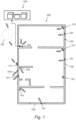
- the security system may comprise at least one detector 101, and preferably a plurality of detectors 101, for detecting an intruder.
- the intruder security system may further comprise at least one control unit 104 which may also be referred to as a gateway.
- the control unit 104 may include a processor 204 and an alarm unit for providing an alarm signal when the security system is set off.
- the control unit 104 is connected to the detectors 101 for receiving signals therefrom.
- the detectors 101 may, for example, be provided with wireless and/or wired communication means for communicating with the control unit 104.
- the control unit 104 may also be connected to input means 105.
- the input means 105 may be a keypad or similar, for arming and disarming the detectors 101 so as to arm and disarm the security system.
- the input means 105 is arranged in the vicinity of the entrance door.
- the input means 105 may be arranged in any suitable location or is a portable device, such as a cell phone.
- the control unit 104 may be connected to an alarm receiving center 106, such as a remote alarm receiving center.
- the control unit 104 may be connected to the alarm receiving center 106 by wires, such as a telephone line as indicated in Fig. 1 with a dashed line, or by a wireless telecommunications system such as GSM or other radio frequency systems.
- the connection may also be through the internet or any other suitable network 107.
- the control unit 104 may be provided with communication means for communicating with the remote alarm receiving center 106.
- the alarm receiving center 106 may be located within the premises or within the building 100.
- control unit 104 may be omitted, and the detectors 101 instead may communicate independently with the alarm receiving center 106, for example, via wireless communication (such as Cat-M LTE).
- the alarm receiving center 106 may alarm one or more operators to a detected intruder.
- the one or more operators may monitor communications received from the intruder security system.
- the one or more operators may, in response to an alarm being triggered, send a patrol unit to the building 100 and/or notify an owner or resident of the building 100.
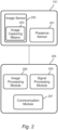
- Fig. 2 shows a detector 101 according to embodiments.
- the detector 101 is a dual sensor detector.
- the detector 101 may be used in the intruder security system of Fig. 1 , or in any other type of intruder security system or alarm system.
- the detector 101 is configured to monitor an area to detect an intruder event.
- An intruder event may be defined as an event where an intrusion has occurred in the monitored area.
- an intruder event may include an event where an intruder is present in the area and/or where an intruder is moving within and/or through the area.
- an intruder event may include a person and/or certain object being present in the area, and/or a motion by a person and/or object being performed in the area.
- Typical objects may include a human body, an animal, a vehicle such as a car or bicycle, or the like.
- the detector 101 comprises at least two different types of sensors.
- a first sensor type may be a presence sensor 201 and second sensor type may be an image sensor 202 or image-based sensor, for example an image sensor 202 comprising image capturing means 203.
- the presence sensor 201 is configured to detect the presence of a person and/or object, for example in the same room as the detector 101 is located.
- the presence sensor 201 may be a movement sensor, a proximity sensor, or any other sensor capable of detecting the presence of a person and/or object.
- the presence sensor 201 is configured to detect movement (e.g. movement of a person and/or object), for example in the same room as the detector 101 is located.
- the movement sensor 201 may include any type of sensor capable of detecting movement of a person and/or object.
- the movement sensor may include a thermal sensor, a microwave presence sensor, or the like.
- the movement sensor may include an infrared sensor such as a passive infrared sensor (also referred to as a PIR sensor).
- the presence sensor 201 is configured to detect a person and/or object being in proximity to the movement sensor, for example in the same room as the detector 101 is located.
- proximity sensors include infrared sensors such as thermal-MOS (TMOS) sensors, or any other sensor suitable for detecting that a person and/or object is in proximity to the sensor.
- the presence sensor may include a low-resolution image sensor capable of detecting the presence of a person and/or object.
- the low-resolution image sensor may have a lower resolution than the image sensor 202, and may be configured to transmit an output signal indicative of whether a person and/or object is present.
- the image sensor 202 and in particular the capturing means 203, is configured to capture one or more images of an area proximate to where the detector 101 is located.
- the image capturing means 203 may capture images of the room where the detector 101 is located.
- the image capturing means 203 may include an imaging device such as a photographic camera or video camera, or any other type of optical sensing device capable of capturing or acquiring one or more images.
- the presence sensor 201 and the image sensor 202 may be arranged to detect an intruder within the same area. That is, the presence sensor 201 may be configured to detect motion in an area corresponding to a field of view of the image capturing sensor 202.
- both the presence sensor 201 and the image sensor 202 may be arranged close to each other and/or facing in substantially the same direction so as to cover the same area of the building 100 or its exterior.
- the presence sensor 201 and the image sensor 202 are arranged in the same housing, e.g. in a housing of an alarm peripheral.
- the presence sensor 201 and the image sensor 202 may be provided in individual housings arranged to be installed in proximity to each other.
- the detector 101 may be placed within the building 100 or at an exterior of the building 100.
- the detector 101 may be placed at an upper comer of a room in the building 100 and, in this instance, may detect an intruder in said room of the building 100.
- the image processing module 206 may determine, based on the taken images, a likelihood value of an intruder event.
- the detector 101 and/or the processor 204 may be configured to control the image processing module 206 to determine the likelihood value.
- the likelihood value determined by the image processing module 206 may also be referred to as an image-based likelihood value.
- the likelihood value may be a value between 0 and 1, where 0 corresponds to no likelihood of an intruder event, and 1 corresponds to a confirmed intruder event.
- a likelihood value of, say, 0.2 corresponds to a low likelihood of an intruder event while a likelihood value of, say, 0.8 corresponds to a high likelihood of an intruder event.
- the sensor threshold value must typically be set sufficiently low such that substantially all intruder events are detected. This is to ensure that the security system does not miss any intruder events (i.e. no false negatives).
- a relatively low threshold value inevitably also results in many false positives (i.e. raising the alarm when there is no intruder).
- the detector 101 allows the threshold value to be higher because it is unlikely that both modes of detection
- Each of the processing modules may additionally compare their respective likelihood values to their respective lower threshold values. For example, if the signal processing module 205 determines that the signal-based likelihood value is below a lower signal threshold value (denoted ts,i_), the signal processing module 205 may be configured to determine that no intruder event has occurred. The processor 204 may then terminate the decision process, e.g. turn off the image sensor 202 and/or the image processing module 206. In other words, the image sensor 202 and/or the image processing module 206 may be configured to enter a dormant state. Hence, battery power may be saved because the image processing module 206 is stopped before it has completed its determination.
- the image processing module 206 may be configured to determine that no intruder event has occurred.
- the processor 204 may then terminate the decision process, e.g. turn off the presence sensor 201 and/or the signal processing module 205.
- the presence sensor 201 and/or the signal processing module 205 may be configured to enter a dormant state. Hence, battery power may be saved because the signal processing module 205 is stopped before it has completed its determination.
- the lower signal threshold value need not be equal to the lower image threshold value.
- the lower signal threshold value may be higher or lower than the lower image threshold value.
- the lower threshold values may be set such that substantially no intruder event occurs when the respective likelihood value is below the lower thresholds.
- the processing modules may classify the likelihood value to be in one of three states: (1) INTRUDER/ALARM (e.g. likely intruder event; likelihood value above higher threshold), (2) NO INTRUDER (e.g. unlikely intruder event; likelihood value below lower threshold), and (3) UNCERTAIN (e.g. inconclusive, neither likely nor likely intruder event; likelihood value between the lower and higher thresholds).
- INTRUDER/ALARM e.g. likely intruder event; likelihood value above higher threshold
- NO INTRUDER e.g. unlikely intruder event; likelihood value below lower threshold
- UNCERTAIN e.g. inconclusive, neither likely nor likely intruder event; likelihood value between the lower and higher thresholds.
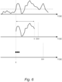
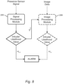
- Fig. 6 shows an exemplary timeline of the detection method according to embodiments.
- Fig. 6 shows three graphs: a top graph showing the signal from the presence sensor 201, a middle graph showing the events of the signal processing module 205, and a bottom graph showing the events of the image processing module 206.
- the three graphs share the same timeline, e.g. an event occurring at a horizontal position on one of the graphs occurs at the same time as an event occurring at the same horizontal position on another of the graphs.
- the top graph shows the signal from the presence sensor 201 as a function of time.
- the signal processing module 205 starts to sample data from the presence sensor 201. This can be seen in the middle graph, where only the sampled data received by the signal processing module 205 is displayed. The sampling lasts for a predetermined time period, which in the shown example is 5 seconds. Once the sampling has been completed, the signal processing module 205 determines the intruder likelihood value as described previously and decides if an intruder event has occurred. Due to the computational time required to process the sampled data and perform the determination, the decision is made at a time DS1 as shown by a dotted line in the middle graph.
- the image sensor 202 starts to capture images.
- the capturing of images is shown as black dots in the bottom graph.
- the image sensor 202 is configured to capture 3 images.
- the second and third images may be captured with a time gap from the respective previous image.
- the image processing module 206 determines the intruder likelihood value as described previously and decides if an intruder event has occurred. Due to the computational time required to process the images and perform the determination, the decision is made at a time DI1 as shown by a dotted line in the bottom graph.
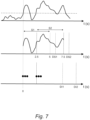
- Fig. 7 shows another exemplary timeline of the detection method according to embodiments.
- the steps performed by the signal processing module 205 (corresponding to steps 305 to 307 in Fig. 3 ) and/or the steps performed by the image processing module 206 (corresponding to steps 309 to 311) are repeated one or more times.
- the signal processing module 205 initiates a second sampling step, indicated by dashed vertical lines and denoted S2, at a predetermined time after initiation of the first sampling step.
- the time between the first and second sampling steps may be less than or more than the shown 2.5 seconds.
- the time between the two steps may be between 0.1 and 10 seconds, optionally between 0.5 and 7 seconds, optionally between 1 and 5 seconds, optionally between 2 and 3 seconds, optionally about 2.5 seconds.
- the second sampling step may at least partially overlap with the first sampling step, i.e. at least some of the presence sensor signal data will be shared between the first and second samplings.
- the second sampling step may be independent from the first sampling step, i.e. no temporal overlap may exist.
- the second sampling step may start when the first sampling step ends.
- the signal processing module 205 may then be configured to determine a second signal-based intruder likelihood value based on the sampled data in the second sampling step.
- the signal processing module 205 then makes a second decision DS2 if an intruder event has occurred. For example, if the first decision from the signal processing module 205 concludes that it is uncertain whether an intruder event has occurred, the second decision may bring more clarity. Thus, if the intruder has moved out of sight (or at least partially out of sight) or is still (i.e. no movement) during the first sample period, the second sample period may still catch the intruder. Accordingly, the accuracy of the detector 101 may be improved.
- the image sensor 202 may additionally be configured to capture a second set of one or more images.
- the image processing module 206 may be configured to determine a second image-based intruder likelihood value. The image processing module 206 then makes a second decision DI2 if an intruder event has occurred. For example, if one or more of the decisions from the signal processing module 205 and/or the first decision from the image processing module 206 concludes that it is uncertain whether an intruder event has occurred, the second image-based decision may bring more clarity. Thus, if the intruder has moved out of sight (or at least partially out of sight) or is still (i.e. no movement) during the first set of images, the second set of images may still catch the intruder. Accordingly, the accuracy of the detector 101 may be improved.
- Fig. 8 shows a flowchart of a detection method according to embodiments where image processing is performed in dependence on the decision by the signal processing module 205.
- the method in Fig. 8 is substantially similar to the previously described method in Figs. 3 to 7 .
- the image processing by the image processing module 206 is only initiated after the signal processing module 205 has made its first decision.
- the image processing module 206 may only start processing the captured images if the signal processing module 205 does not trigger the alarm, i.e. if the signal-based likelihood value is below the signal threshold value.
- the image-based llikelihood value may only be determined in response to, or if, the signal-based likelihood value is below the sensor threshold value. Accordingly, the relatively more power consuming image processing module 206 is only activated if the signal processing module 205 is unsure whether an intruder event has occurred.
- the image processing module 206 and the image processing procedure is performed in dependency on the outcome of the signal processing module and, in particular, the signal-based intruder likelihood value.
- This dependency is indicated in Fig. 8 by dashed lines.
- the image processing module 206 may perform some, but not all, of its processing steps before the decision is taken by the signal processing module 205, while the remaining steps are performed only when the signal processing module 205 has determined that the signal-based likelihood value is below the sensor threshold value.
- the image processing module 206 may perform preparatory steps, such as changing the resolution of the images, adjusting parameters of the images, cropping the images, calculating or determining differences between the images, or the like before a decision is taken by the signal processing module 205.
- intensely power consuming steps such as image recognition or determination of the image-based likelihood value, may be performed only once the signal processing module 205 has decided that it is not certain if an intruder event has taken place.
- Fig. 9 shows a further implementation of the method in Fig. 8 where lower thresholds have been introduced into the decision-making process.
- each of the processing modules may additionally compare their respective likelihood values to respective lower threshold values, as described previously in relation to Fig. 5 .
- image processing is only performed when the signal processing module 205 is uncertain whether an intruder event has occurred. That is, the image processing is not performed if the signal processing module 205 has determined that an intruder event (with high likelihood) has taken place (and thus triggered the alarm) or that an intruder event (with high likelihood) has not taken place (and thus terminated the detection process).
- the power consumption of the detector 101 may be reduced, and the battery life of the detector 101 may be increased. While power consumption is reduced, the high accuracy of the detector 101 may still be achieved by the dual detection, especially in cases where the presence sensor 201 data is inconclusive. Similarly, and as has been described previously, the number of false positives (triggering the alarm when no intruder event has occurred) is also reduced because the threshold levels may be increased when two sensors are used.
- the detector 101 may further be configured to dynamically adjust the signal threshold values and the image threshold values.
- the dynamical adjustment applies to any suitable detector 101, including the detectors 101 described in relation to Figs. 2 to 9 .
- the detector 101 may be configured to adjust the threshold values to weigh the decisions from the signal processing module 205 and the image processing module 206. For example, by increasing the sensor threshold value and/or decreasing the image threshold value, the image sensor 202 will have more influence in the final decision. Conversely, by increasing the image threshold value and/or decreasing the sensor threshold value, the presence sensor 201 will have more influence in the final decision.
- the detector 101 may tailor the threshold values such that the most appropriate sensor in a given environment has more influence. For example, if the area where the detector 101 is located is dark, has limited light, and/or has an unclear visual sight, the threshold values may be adjusted such that the presence sensor 201 is more influential. As another example, if the area where the detector 101 is located is warm (e.g. the temperature is relatively close to the body temperature of humans), the threshold values may be adjusted such that the image sensor 202 is more influential.
- the threshold values may be adjusted such that the presence sensor 201 is more influential, while at daytime the threshold values may be adjusted such that the image sensor 202 is more influential.
- the detector 101 may comprise an ambient sensor to determine one or more ambient properties in dependence on which the adjustment of the threshold values may be made.
- the ambient properties may include an ambient temperature, an ambient light amount, a time of day, or any other ambient property that may influence the performance of the presence sensor 201 and/or the image sensor 202.
- the ambient sensor may include a temperature sensor, an ambient light sensor, a means for determining the time, or the like.
- the detector 101 may alternatively or additionally receive information, e.g. from the control unit 104, comprising data regarding the time of day (e.g. a timestamp), or any other ambient property including temperature and/or ambient light amount.
- the detector may alternatively or additionally use pixel data (e.g. luminance data) from the one or more captured images by the image sensor 202 to determine an ambient light amount.
- Fig. 10 shows a method of processing a plurality of images.
- the image processing method may be used by the image processing module 206 to process the images captured by the image capturing means 203 of the image sensor 202.
- the image processing module 206 is configured to perform the processing method according to Fig. 10 .
- step 1001 at least two images are provided.
- the images may be captured by the image capturing means 203 of an image sensor 202, or they may be provided by any other suitable means.
- the images may be provided to an image processing module 206, such as the image processing module 206 of a detector 101 according to embodiments.
- step 1003 the resolution of the images is reduced.
- the images are downsampled to a lower resolution.
- the computational power required to process the images, and in particular to perform steps 1005 to 1007, may be reduced.
- a difference in an image parameter between two of the downsampled images may be identified and/or calculated.
- the difference may be calculated per pixel of the downsampled images, per group of adjacent pixels (e.g. per group of 2, 4, 9 pixels or the like) of the downsampled images, per sub-area of the downsampled images, or the like.
- an output will be obtained comprising the difference mapped out across the pixel grid of the image.
- the image parameter may be a luminance parameter, for example the Y-channel of an image in the YUV-format.
- a difference in luminance between the two images may be calculated and mapped out on the pixel grid of the images.
- the inventors have realised that a difference in luminance typically corresponds to movement of an object between two images.
- an area of the images is identified where the difference in the image perimeter is present. For example, an area may be identified where the difference in the image parameter is greater than a lower threshold and/or lower than a higher threshold. As another example, an area may be identified where the difference is relatively large (e.g. compared to other areas). Hence, an area of the images where movement is likely to have occurred is identified.
- the images are cropped to the identified area.
- the images being cropped may be high-resolution images, such as the original versions of the images captured by the image capturing means 203 of the image sensor 202.
- the downsampled images are only used to identify the relevant areas, whereas further image processing to determine an intruder likelihood value may be performed on versions of the images with higher resolution, thus increasing the accuracy of the image processing.
- step 1011 further processing is performed on the cropped images.
- the further processing may include performing image recognition to determine whether a preset object (e.g. a person) exists in the picture, determining an intruder likelihood value (as described previously), or the like.
- more than two images may be used by the image processing module 206 to determine the intruder likelihood value.
- two of the images may be used in steps 1003 to 1007 to calculate the luminance (or other image parameter) difference and identify the area of interest.
- all images may be cropped in step 1009 and the image processing module 206 may also be configured to perform the further processing in step 1011 to all (cropped) images to determine the likelihood value.
- the calculated difference in the image parameter may also be used to adjust the image threshold value. For example, if there is a large difference in the image parameter (e.g. luminance) between two captured images (as calculated in step 1005), the inventors have found that this large difference indicates movement of an intruder. Thus, in response to said difference, the image threshold value may be reduced such that the image processing module 206 may trigger the alarm even if the image-based intruder likelihood value is relatively low. For instance, if the difference in the image property is greater than a threshold amount and/or the difference is greater than a threshold amount for at least a minimum number of pixels, the image threshold value may be reduced.
- the image threshold value may be reduced if the difference in the image property is greater than a threshold amount and/or the difference is greater than a threshold amount for at least a minimum number of pixels.
- the detector 101 according to embodiments and the image processing method according to embodiments may be used in many other apparatuses or systems where the accuracy of detection is improved by the use of dual sensors.
Landscapes
- Engineering & Computer Science (AREA)
- Physics & Mathematics (AREA)
- General Physics & Mathematics (AREA)
- Multimedia (AREA)
- Theoretical Computer Science (AREA)
- Computer Vision & Pattern Recognition (AREA)
- Signal Processing (AREA)
- Computer Security & Cryptography (AREA)
- Burglar Alarm Systems (AREA)
- Alarm Systems (AREA)
Priority Applications (3)
| Application Number | Priority Date | Filing Date | Title |
|---|---|---|---|
| EP23217435.9A EP4576035A1 (de) | 2023-12-18 | 2023-12-18 | Alarmdetektor mit zwei sensoren |
| ARP240103505A AR134718A1 (es) | 2023-12-18 | 2024-12-17 | Detector para un sistema de seguridad, sistema de seguridad que comprende dicho detector y método para generar una alarma en función de la detección de un intruso mediante dicho detector |
| PCT/EP2024/086727 WO2025132311A1 (en) | 2023-12-18 | 2024-12-17 | Ai based alarm detector with dual sensors |
Applications Claiming Priority (1)
| Application Number | Priority Date | Filing Date | Title |
|---|---|---|---|
| EP23217435.9A EP4576035A1 (de) | 2023-12-18 | 2023-12-18 | Alarmdetektor mit zwei sensoren |
Publications (1)
| Publication Number | Publication Date |
|---|---|
| EP4576035A1 true EP4576035A1 (de) | 2025-06-25 |
Family
ID=89223418
Family Applications (1)
| Application Number | Title | Priority Date | Filing Date |
|---|---|---|---|
| EP23217435.9A Pending EP4576035A1 (de) | 2023-12-18 | 2023-12-18 | Alarmdetektor mit zwei sensoren |
Country Status (3)
| Country | Link |
|---|---|
| EP (1) | EP4576035A1 (de) |
| AR (1) | AR134718A1 (de) |
| WO (1) | WO2025132311A1 (de) |
Citations (3)
| Publication number | Priority date | Publication date | Assignee | Title |
|---|---|---|---|---|
| US20050071883A1 (en) * | 2003-09-26 | 2005-03-31 | Oh Jong Sang | Remote monitoring system and method for controlling the same |
| WO2013013082A1 (en) * | 2011-07-19 | 2013-01-24 | Utah State University Research Foundation | Systems, devices, and methods for multi-occupant tracking |
| US20210358293A1 (en) * | 2019-04-29 | 2021-11-18 | Alarm.Com Incorporated | Machine learning motion sensing with auxiliary sensors |
-
2023
- 2023-12-18 EP EP23217435.9A patent/EP4576035A1/de active Pending
-
2024
- 2024-12-17 WO PCT/EP2024/086727 patent/WO2025132311A1/en active Pending
- 2024-12-17 AR ARP240103505A patent/AR134718A1/es unknown
Patent Citations (3)
| Publication number | Priority date | Publication date | Assignee | Title |
|---|---|---|---|---|
| US20050071883A1 (en) * | 2003-09-26 | 2005-03-31 | Oh Jong Sang | Remote monitoring system and method for controlling the same |
| WO2013013082A1 (en) * | 2011-07-19 | 2013-01-24 | Utah State University Research Foundation | Systems, devices, and methods for multi-occupant tracking |
| US20210358293A1 (en) * | 2019-04-29 | 2021-11-18 | Alarm.Com Incorporated | Machine learning motion sensing with auxiliary sensors |
Also Published As
| Publication number | Publication date |
|---|---|
| AR134718A1 (es) | 2026-03-04 |
| WO2025132311A1 (en) | 2025-06-26 |
Similar Documents
| Publication | Publication Date | Title |
|---|---|---|
| EP1782406B1 (de) | Überwachungsvorrichtungen | |
| RU2628745C2 (ru) | Система защитного наблюдения и соответствующий способ инициирования тревожной сигнализации | |
| CA2658347C (en) | Intruder detection using video and infrared data | |
| AU2020215581B2 (en) | Smart surveillance system for swimming pools | |
| KR102233679B1 (ko) | Ess 침입자 및 화재 감지 장치 및 방법 | |
| KR101467352B1 (ko) | 위치기반 통합관제시스템 | |
| WO2009099511A1 (en) | Video sensor and alarm system and method with object and event classification | |
| CA2623501A1 (en) | Security monitoring arrangement and method using a common field of view | |
| JP2019066452A (ja) | 在宅管理システム及びそれに用いる在不在判定端末とコンピュータプログラム | |
| EP4595031A1 (de) | Bilderfassungsanordnungen und -verfahren | |
| JP2010182021A (ja) | 画像監視システム | |
| KR20150041939A (ko) | 실시간 이벤트 감지를 통한 도어 감시시스템 및 그 방법 | |
| KR20160095901A (ko) | 홈네트워크 시스템과 연동하는 안전창호를 이용한 방범시스템 | |
| CN111917967A (zh) | 门监控系统及其控制方法 | |
| KR101046819B1 (ko) | 소프트웨어 휀스에 의한 침입감시방법 및 침입감시시스템 | |
| KR100316268B1 (ko) | 영상 전송용 보안 시스템 | |
| EP4576035A1 (de) | Alarmdetektor mit zwei sensoren | |
| EP2698773A1 (de) | Einbruchmeldeanlage und Verfahren zur Scharfschaltung einer Einbruchmeldeanlage | |
| US20230071428A1 (en) | Security system with ferromagnetic sensing | |
| CN111311786A (zh) | 智能门锁系统及其智能门锁控制方法 | |
| EP4727114A1 (de) | Auf künstlicher intelligenz basierende videooptimierung für ein überwachungssystem | |
| KR20170073904A (ko) | 홈 네트워크를 이용한 세대 방범시스템 | |
| JP2007183845A (ja) | 監視装置 | |
| JP2024145293A (ja) | 画像処理装置及び画像処理プログラム | |
| KR20010001532A (ko) | 무인보안 경보시스템 |
Legal Events
| Date | Code | Title | Description |
|---|---|---|---|
| PUAI | Public reference made under article 153(3) epc to a published international application that has entered the european phase |
Free format text: ORIGINAL CODE: 0009012 |
|
| STAA | Information on the status of an ep patent application or granted ep patent |
Free format text: STATUS: THE APPLICATION HAS BEEN PUBLISHED |
|
| AK | Designated contracting states |
Kind code of ref document: A1 Designated state(s): AL AT BE BG CH CY CZ DE DK EE ES FI FR GB GR HR HU IE IS IT LI LT LU LV MC ME MK MT NL NO PL PT RO RS SE SI SK SM TR |
|
| STAA | Information on the status of an ep patent application or granted ep patent |
Free format text: STATUS: REQUEST FOR EXAMINATION WAS MADE |
|
| 17P | Request for examination filed |
Effective date: 20251212 |