EP4576040A1 - Objekterkennung im dunkeln beim fahrzeugbetrieb - Google Patents
Objekterkennung im dunkeln beim fahrzeugbetrieb Download PDFInfo
- Publication number
- EP4576040A1 EP4576040A1 EP24188562.3A EP24188562A EP4576040A1 EP 4576040 A1 EP4576040 A1 EP 4576040A1 EP 24188562 A EP24188562 A EP 24188562A EP 4576040 A1 EP4576040 A1 EP 4576040A1
- Authority
- EP
- European Patent Office
- Prior art keywords
- vehicle
- objects
- computer
- component
- illuminated area
- Prior art date
- Legal status (The legal status is an assumption and is not a legal conclusion. Google has not performed a legal analysis and makes no representation as to the accuracy of the status listed.)
- Pending
Links
Images












Classifications
-
- G—PHYSICS
- G08—SIGNALLING
- G08G—TRAFFIC CONTROL SYSTEMS
- G08G1/00—Traffic control systems for road vehicles
- G08G1/01—Detecting movement of traffic to be counted or controlled
- G08G1/04—Detecting movement of traffic to be counted or controlled using optical or ultrasonic detectors
-
- B—PERFORMING OPERATIONS; TRANSPORTING
- B60—VEHICLES IN GENERAL
- B60W—CONJOINT CONTROL OF VEHICLE SUB-UNITS OF DIFFERENT TYPE OR DIFFERENT FUNCTION; CONTROL SYSTEMS SPECIALLY ADAPTED FOR HYBRID VEHICLES; ROAD VEHICLE DRIVE CONTROL SYSTEMS FOR PURPOSES NOT RELATED TO THE CONTROL OF A PARTICULAR SUB-UNIT
- B60W40/00—Estimation or calculation of non-directly measurable driving parameters for road vehicle drive control systems not related to the control of a particular sub unit, e.g. by using mathematical models
- B60W40/02—Estimation or calculation of non-directly measurable driving parameters for road vehicle drive control systems not related to the control of a particular sub unit, e.g. by using mathematical models related to ambient conditions
-
- B—PERFORMING OPERATIONS; TRANSPORTING
- B60—VEHICLES IN GENERAL
- B60Q—ARRANGEMENT OF SIGNALLING OR LIGHTING DEVICES, THE MOUNTING OR SUPPORTING THEREOF OR CIRCUITS THEREFOR, FOR VEHICLES IN GENERAL
- B60Q1/00—Arrangement of optical signalling or lighting devices, the mounting or supporting thereof or circuits therefor
- B60Q1/02—Arrangement of optical signalling or lighting devices, the mounting or supporting thereof or circuits therefor the devices being primarily intended to illuminate the way ahead or to illuminate other areas of way or environments
- B60Q1/04—Arrangement of optical signalling or lighting devices, the mounting or supporting thereof or circuits therefor the devices being primarily intended to illuminate the way ahead or to illuminate other areas of way or environments the devices being headlights
- B60Q1/06—Arrangement of optical signalling or lighting devices, the mounting or supporting thereof or circuits therefor the devices being primarily intended to illuminate the way ahead or to illuminate other areas of way or environments the devices being headlights adjustable, e.g. remotely-controlled from inside vehicle
-
- B—PERFORMING OPERATIONS; TRANSPORTING
- B60—VEHICLES IN GENERAL
- B60Q—ARRANGEMENT OF SIGNALLING OR LIGHTING DEVICES, THE MOUNTING OR SUPPORTING THEREOF OR CIRCUITS THEREFOR, FOR VEHICLES IN GENERAL
- B60Q1/00—Arrangement of optical signalling or lighting devices, the mounting or supporting thereof or circuits therefor
- B60Q1/02—Arrangement of optical signalling or lighting devices, the mounting or supporting thereof or circuits therefor the devices being primarily intended to illuminate the way ahead or to illuminate other areas of way or environments
- B60Q1/04—Arrangement of optical signalling or lighting devices, the mounting or supporting thereof or circuits therefor the devices being primarily intended to illuminate the way ahead or to illuminate other areas of way or environments the devices being headlights
- B60Q1/06—Arrangement of optical signalling or lighting devices, the mounting or supporting thereof or circuits therefor the devices being primarily intended to illuminate the way ahead or to illuminate other areas of way or environments the devices being headlights adjustable, e.g. remotely-controlled from inside vehicle
- B60Q1/08—Arrangement of optical signalling or lighting devices, the mounting or supporting thereof or circuits therefor the devices being primarily intended to illuminate the way ahead or to illuminate other areas of way or environments the devices being headlights adjustable, e.g. remotely-controlled from inside vehicle automatically
-
- B—PERFORMING OPERATIONS; TRANSPORTING
- B60—VEHICLES IN GENERAL
- B60W—CONJOINT CONTROL OF VEHICLE SUB-UNITS OF DIFFERENT TYPE OR DIFFERENT FUNCTION; CONTROL SYSTEMS SPECIALLY ADAPTED FOR HYBRID VEHICLES; ROAD VEHICLE DRIVE CONTROL SYSTEMS FOR PURPOSES NOT RELATED TO THE CONTROL OF A PARTICULAR SUB-UNIT
- B60W30/00—Purposes of road vehicle drive control systems not related to the control of a particular sub-unit, e.g. of systems using conjoint control of vehicle sub-units
- B60W30/08—Active safety systems predicting or avoiding probable or impending collision or attempting to minimise its consequences
- B60W30/09—Taking automatic action to avoid collision, e.g. braking and steering
-
- B—PERFORMING OPERATIONS; TRANSPORTING
- B60—VEHICLES IN GENERAL
- B60W—CONJOINT CONTROL OF VEHICLE SUB-UNITS OF DIFFERENT TYPE OR DIFFERENT FUNCTION; CONTROL SYSTEMS SPECIALLY ADAPTED FOR HYBRID VEHICLES; ROAD VEHICLE DRIVE CONTROL SYSTEMS FOR PURPOSES NOT RELATED TO THE CONTROL OF A PARTICULAR SUB-UNIT
- B60W30/00—Purposes of road vehicle drive control systems not related to the control of a particular sub-unit, e.g. of systems using conjoint control of vehicle sub-units
- B60W30/08—Active safety systems predicting or avoiding probable or impending collision or attempting to minimise its consequences
- B60W30/095—Predicting travel path or likelihood of collision
- B60W30/0956—Predicting travel path or likelihood of collision the prediction being responsive to traffic or environmental parameters
-
- G—PHYSICS
- G06—COMPUTING OR CALCULATING; COUNTING
- G06V—IMAGE OR VIDEO RECOGNITION OR UNDERSTANDING
- G06V20/00—Scenes; Scene-specific elements
- G06V20/50—Context or environment of the image
- G06V20/56—Context or environment of the image exterior to a vehicle by using sensors mounted on the vehicle
- G06V20/58—Recognition of moving objects or obstacles, e.g. vehicles or pedestrians; Recognition of traffic objects, e.g. traffic signs, traffic lights or roads
-
- G—PHYSICS
- G06—COMPUTING OR CALCULATING; COUNTING
- G06V—IMAGE OR VIDEO RECOGNITION OR UNDERSTANDING
- G06V20/00—Scenes; Scene-specific elements
- G06V20/50—Context or environment of the image
- G06V20/56—Context or environment of the image exterior to a vehicle by using sensors mounted on the vehicle
- G06V20/58—Recognition of moving objects or obstacles, e.g. vehicles or pedestrians; Recognition of traffic objects, e.g. traffic signs, traffic lights or roads
- G06V20/584—Recognition of moving objects or obstacles, e.g. vehicles or pedestrians; Recognition of traffic objects, e.g. traffic signs, traffic lights or roads of vehicle lights or traffic lights
-
- G—PHYSICS
- G08—SIGNALLING
- G08G—TRAFFIC CONTROL SYSTEMS
- G08G1/00—Traffic control systems for road vehicles
- G08G1/16—Anti-collision systems
- G08G1/164—Centralised systems, e.g. external to vehicles
-
- G—PHYSICS
- G08—SIGNALLING
- G08G—TRAFFIC CONTROL SYSTEMS
- G08G1/00—Traffic control systems for road vehicles
- G08G1/16—Anti-collision systems
- G08G1/166—Anti-collision systems for active traffic, e.g. moving vehicles, pedestrians, bikes
-
- B—PERFORMING OPERATIONS; TRANSPORTING
- B60—VEHICLES IN GENERAL
- B60Q—ARRANGEMENT OF SIGNALLING OR LIGHTING DEVICES, THE MOUNTING OR SUPPORTING THEREOF OR CIRCUITS THEREFOR, FOR VEHICLES IN GENERAL
- B60Q2300/00—Indexing codes for automatically adjustable headlamps or automatically dimmable headlamps
- B60Q2300/05—Special features for controlling or switching of the light beam
-
- B—PERFORMING OPERATIONS; TRANSPORTING
- B60—VEHICLES IN GENERAL
- B60Q—ARRANGEMENT OF SIGNALLING OR LIGHTING DEVICES, THE MOUNTING OR SUPPORTING THEREOF OR CIRCUITS THEREFOR, FOR VEHICLES IN GENERAL
- B60Q2300/00—Indexing codes for automatically adjustable headlamps or automatically dimmable headlamps
- B60Q2300/40—Indexing codes relating to other road users or special conditions
- B60Q2300/42—Indexing codes relating to other road users or special conditions oncoming vehicle
-
- B—PERFORMING OPERATIONS; TRANSPORTING
- B60—VEHICLES IN GENERAL
- B60Q—ARRANGEMENT OF SIGNALLING OR LIGHTING DEVICES, THE MOUNTING OR SUPPORTING THEREOF OR CIRCUITS THEREFOR, FOR VEHICLES IN GENERAL
- B60Q2300/00—Indexing codes for automatically adjustable headlamps or automatically dimmable headlamps
- B60Q2300/40—Indexing codes relating to other road users or special conditions
- B60Q2300/45—Special conditions, e.g. pedestrians, road signs or potential dangers
Definitions
- the subject disclosure relates generally to object detection in darkness during vehicle operation.
- a system comprises a processor that executes computer-executable components stored in a non-transitory computer-readable memory, the computer-executable components comprising: an identification component that detects one or more objects on or alongside a road; a recognition component that detects light from an approaching vehicle to determine an illuminated area, and determines if the one or more objects are located in the illuminated area; and an analysis component that performs, in response to a determination that the one or more objects are not located in the illuminated area, a risk assessment on the one or more objects based on parameters of the one or more objects.
- computer-implemented method comprises: detecting one or more objects on or alongside a road; detecting light from an approaching vehicle to determine an illuminated area, and determining if the one or more objects are located in the illuminated area; and performing, in response to a determination that the one or more objects are not located in the illuminated area, a risk assessment on the one or more objects based on parameters of the one or more objects.
- a computer program product comprises a non-transitory computer-readable memory having program instructions embodied therewith, the program instructions executable by a processor to cause the processor to: detect one or more objects on or alongside a road; detect light from an approaching vehicle to determine an illuminated area, and determine if the one or more objects are located in the illuminated area; and perform, in response to a determination that the one or more objects are not located in the illuminated area, a risk assessment on the one or more objects based on parameters of the one or more objects.
- the above-described systems can be implemented as computer-implemented methods or computer program products.
- Object detection while driving a vehicle plays a crucial role in enhancing road safety by identifying and tracking various objects such as vehicles, pedestrians, and obstacles in the vehicle's vicinity.
- Object detection often implemented through sensors and cameras, enables real-time analysis of the surroundings of the vehicle, providing essential data for driver assistance systems, collision avoidance, and overall improved situational awareness.
- object detection can reduce the risk of collisions and improve overall visibility in challenging low-light conditions (e.g., at night, in a poorly lit tunnel).
- existing object detection systems rely on ambient light at night, such as moonlight or street lighting. In areas with poor lighting conditions, these systems may struggle to effectively and accurately detect objects near or on a road that can cause potential hazardous situations (e.g., a child running onto a road, a large traffic cone in the road).
- Traditional headlights provide limited illumination in the dark, and their range is often insufficient for detecting objects at a distance in the dark or during the nighttime.
- the focused beam of headlights may create shadows, making it difficult to identify objects that are partially obscured.
- many vehicles use sensors for object detection. However, these sensors may have a limited detection range and may not be able to identify objects at a sufficient distance, especially in complete darkness. Identifying wildlife in the dark also remains a challenge, as the lack of ambient light and the variability in animal movements make it difficult for existing systems to reliably detect and classify animals.
- One or more embodiments described herein can address one or more of these technical problems.
- One or more embodiments described herein can include systems, computer-implemented methods, apparatus, or computer program products that can facilitate object detection in darkness for vehicle operation. That is, the present inventors realized that various disadvantages are associated with existing techniques for performing object detection in darkness.
- an identification component can detect one or more objects on or alongside a road.
- the identification component can engage sensors on a vehicle to detect objects (e.g., animals, pedestrians, bikers)
- a recognition component can detect light from an approaching vehicle to determine an illuminated area, and determine if the one or more objects are located in the illuminated area. For example, the recognition component can determine if an identified deer near a road is within the detected light from the approaching vehicle (e.g., is visible to the approaching vehicle).
- an analysis component can perform, in response to a determination that the one or more objects are not located in the illuminated area, a risk assessment on the one or more objects based on parameters of the one or more objects.
- the analysis component can perform a risk assessment to determine a risk level associated with the identified deer (e.g., poses higher risk if deer is running towards the road, poses less risk is deer is standing farther from the road).
- a risk level associated with the identified deer e.g., poses higher risk if deer is running towards the road, poses less risk is deer is standing farther from the road.
- an execution component can notify the approaching vehicle of the detected object or perform actions that can enable the detected object to be visible to the approaching vehicle (e.g., change light intensity on the approaching vehicle, change headlight angles of the approaching vehicle).
- vehicles equipped with appropriate sensors to perform object detection in dark environments can enable other vehicles not equipped with such technology to obtain enhanced visibility and awareness.
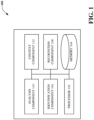
- FIG. 1 illustrates an example, non-limiting block diagram 100 showing a vehicle system, where such vehicle can facilitate object detection in darkness for vehicle operation in accordance with one or more embodiments described herein.
- the vehicle can be any suitable vehicle or automobile (e.g., can be a car, a truck, a van, a motorcycle, plane, boat, helicopter).
- the vehicle can have or otherwise exhibit any suitable type of propulsion system (e.g., can be an electric vehicle, can be a gasoline-powered or diesel-powered vehicle, can be a hybrid vehicle).
- the vehicle can be driving on any suitable road, street, lane, or highway at any suitable speed.
- the vehicle can, while driving, be stopped at an intersection, at a traffic light, at a stop sign, at a cross-walk, or at a traffic jam.
- the vehicle can be parked rather than driving (e.g., can be parked in a parking lot, by a curb, or in a driveway).
- the vehicle can comprise, have, or otherwise be outfitted or equipped with the system 100.
- the system 100 can be onboard the vehicle.
- the system 100 can comprise a processor 102 (e.g., computer processing unit, microprocessor) and a non-transitory computer-readable memory 104 that is operably or operatively or communicatively connected or coupled to the processor 102.
- the non-transitory computer-readable memory 104 can store computer-executable instructions which, upon execution by the processor 102, can cause the processor 102 or other components of the system 100 (e.g., identification component 106, recognition component 108, analysis component 110, context component 112) to perform one or more acts.
- the non-transitory computer-readable memory 104 can store computer-executable components (e.g., identification component 106, recognition component 108, analysis component 110, context component 112), and the processor 102 can execute the computer-executable components.
- computer-executable components e.g., identification component 106, recognition component 108, analysis component 110, context component 112
- the processor 102 can execute the computer-executable components.
- the system 100 can comprise an identification component 106.
- the identification component 106 can detect one or more objects on or alongside a road (e.g., a child walking towards the road, a construction cone in the middle of a lane, wildlife near the road).
- the system 100 can comprise a recognition component 108.
- the recognition component 108 can detect light from an approaching vehicle to determine an illuminated area, and determine if the one or more objects are located in the illuminated area. For example, the recognition component 108 can determine if a pedestrian near a road is located within the illuminated area caused by the headlights of an approaching vehicle. In other words, the recognition component 108 can determine if the one or more detected objects are visible to the driver of the approaching vehicle.
- the approaching vehicle can be any vehicle approaching from a different direction or any vehicle from which the headlights are visible (e.g., a vehicle turning onto the road, a vehicle driving in the opposite lane).
- the recognition component 108 can detect the illuminated area from an approaching vehicle using computer vision algorithms.
- the computer vision algorithms the recognition component 108 can use, but are not limited to, are histogram analysis, thresholding, or color conversion of images (e.g., conversion to grayscale, conversion to black and white).
- the recognition component 108 can employ a timer condition to determine if the one or more objects are located within the illuminated area. More specifically, if a detected object is located within the illuminated area but moves out of the illuminated area before a defined short period of time, the recognition component 108 can ultimately determine that the detected object is not in the illuminated area. If the detected object is located outside the illuminated area but moves into the illuminated area after the defined short period of time, the recognition component 108 can ultimately determine that the detected object is located in the illuminated area. Conversely, if the detected object remains in the illuminated area or remains outside the illuminated area for a time longer than the defined short period of time, the recognition component 108 can assume with higher certainty that the object has been detected. In various instances, the timer condition can enforce assurance that an object has been detected.
- the system 100 can comprise an analysis component 110.
- the analysis component 110 can perform , in response to a determination that the one or more objects are not located in the illuminated area (e.g., are not visible to the approaching vehicle), a risk assessment on the one or more objects based on parameters of the one or more objects. More specifically, the analysis component 110 can employ information about the detected one or more objects (e.g., movement, type of object, capability of moving, location) to determine a risk level (e.g., non-risky, risky, very risky) assigned to the one or more objects.
- a risk level e.g., non-risky, risky, very risky
- the system 100 can comprise a context component 112.
- the context component 112 can determine if external light conditions meet a defined threshold for darkness. More specifically, the context component 112 can determine if the external light conditions lack sufficient illumination such that approaching vehicles may not see objects on a road that can cause hazards (e.g., too dark to see a deer near the road).
- the identification component 106 can automatically start to detect objects based on a determination that external light conditions meet a defined threshold for darkness. For example, the identification component 106 can be refrain from object detection if a vehicle is driving in daylight, as approaching vehicles are capable of seeing objects on or alongside a road. As another example, if a vehicle enters a tunnel that is dimly lit, the context component 112 can determine that light conditions meet the defined threshold for darkness, and therefore the identification component 106 can begin to perform object detection in response to the determination.
- FIG. 2 illustrates a block diagram of an example, non-limiting system 200 that can facilitate object detection in darkness for vehicle operation in accordance with one or more embodiments described herein.
- the system 200 can, in some cases, comprise the same components as the system 100, and can further comprise an execution component 202.
- the execution component 202 can conduct, initiate, facilitate, or otherwise perform any suitable electronic actions, in response to the analysis component 110 (e.g., in response to a determination of a risk level of one or more detected objects). In contrast, the execution component 202 can, in various instances, refrain from conducting, initiating, facilitating, or otherwise performing such electronic actions, in response to the analysis component 110.
- the execution component 202 can, in response to a determination that the one or more objects are risky or very risky (e.g., wildlife running into the road, a biker riding into the road), display an electronic notification to the driver of the approaching vehicle on any type of vehicle display (e.g., dashboard display, head-up display).
- the electronic notification can comprise any corresponding warning message.
- the identification component 106 detects an inattentive pedestrian walking across the street
- the recognition component 108 can determine an illuminated area from a detected approaching vehicle, and can further determine that the pedestrian is not in the illuminated area.
- the analysis component 110 can perform a risk assessment to determine that the pedestrian is very risky due to the type of object and movement direction. Therefore, the execution component 202 can, for example, instruct the driver of the approaching vehicle to slow down and increase intensity of the headlights.
- the execution component 202 can, in response to a determination that the one or more objects are risky or very risky, modify driving of the vehicle or the approaching vehicle. For example, the execution component 202 can perform a lane change, slow down, or speed up the vehicle to avoid a potential accident (e.g., avoid collision with the object, avoid collision with the approaching vehicle if the approaching vehicle collides with the object). Furthermore, the execution component 202 can, if equipped with dynamic bend lighting, illuminate the object by turning the angle of the headlights towards the object, thus enabling the approaching vehicle to see the object. Moreover, the execution component 202 can also increase intensity of the lights on the vehicle to illuminate the object and allow the approaching vehicle to see the object.
- a potential accident e.g., avoid collision with the object, avoid collision with the approaching vehicle if the approaching vehicle collides with the object.
- the execution component 202 can, if equipped with dynamic bend lighting, illuminate the object by turning the angle of the headlights towards the object, thus enabling the approaching vehicle to see the object.
- FIG. 3 illustrates a block diagram of an example, non-limiting system 300 that can facilitate object detection in darkness for vehicle operation in accordance with one or more embodiments described herein.
- the system 300 can, in some cases, comprise the same components as the system 200, and can further comprise a sensor component 302, an inference component 318, and a deep learning neural network 320.
- the sensor component 302 can obtain, via any suitable sensors of the vehicle, vicinity data 304.
- the vicinity data 304 can exhibit any suitable format, size, or dimensionality.
- the vicinity data 304 can comprise one or more scalars, one or more vectors, one or more matrices, one or more tensors, one or more character strings, or any suitable combination thereof.
- the sensor component 302 can electronically control, electronically execute, electronically activate, or otherwise electronically access any suitable sensors of the vehicle.
- sensors can be external or road-facing.
- sensors can be oriented or otherwise configured to monitor the vicinity (e.g., the surroundings of the vehicle) as the vehicle drives around or is parked.
- such sensors can include a set of vehicle cameras 306.
- the set of vehicle cameras 306 can include any suitable number of any suitable types of cameras (e.g., of image-capture devices).
- the set of vehicle cameras 306 can be integrated into or onto the vehicle.
- one or more of the set of vehicle cameras 306 can be forward-facing.
- such one or more cameras can be integrated into or onto any suitable forward-facing surfaces, whether interior or exterior, of the vehicle (e.g., can be built on a dash of the vehicle so as to look through a front windshield of the vehicle, can be built around the front windshield of the vehicle, can be built into a front bumper of the vehicle, can be built around headlights of the vehicle, can be built into a hood of the vehicle). Because such one or more cameras can be forward-facing, such one or more cameras can be configured to capture or otherwise record images or video frames of portions of the vicinity that lie in front of the vehicle. In various aspects, one or more of the set of vehicle cameras 306 can be rearward-facing.
- such one or more cameras can be integrated into or onto any suitable rearward-facing surfaces, whether interior or exterior, of the vehicle (e.g., can be built into or on a rearview mirror of the vehicle, can be built into or onto sideview mirrors of the vehicle, can be built around a rear windshield of the vehicle, can be built into a rear bumper of the vehicle, can be built around taillights of the vehicle, can be built into a trunk-cover of the vehicle).
- a rearward-facing such one or more cameras can be configured to capture or otherwise record images or video frames of portions of the vicinity that lie behind the vehicle.
- one or more of the set of vehicle cameras 306 can be laterally-facing.
- such one or more cameras can be integrated into or onto any suitable lateral surfaces, whether interior or exterior, of the vehicle (e.g., can be built into or around doors or door handles of the vehicle, can be built into or around fenders of the vehicle). Because such one or more cameras can be laterally-facing, such one or more cameras can be configured to capture or otherwise record images or video frames of portions of the vicinity that lie beside the vehicle.
- such sensors can include a set of vehicle microphones 308.
- the set of vehicle microphones 308 can include any suitable number of any suitable types of microphones (e.g., of sound-capture devices).
- the set of vehicle microphones 308 can be integrated into or onto the vehicle.
- one or more of the set of vehicle microphones 308 can be forward-facing.
- such one or more microphones can be integrated into or onto any suitable forward-facing surfaces, whether interior or exterior, of the vehicle, so as to capture or otherwise record sounds or noises that occur in portions of the vicinity that lie in front of the vehicle.
- one or more of the set of vehicle microphones 308 can be rearward-facing.
- such one or more microphones can be integrated into or onto any suitable rearward-facing surfaces, whether interior or exterior, of the vehicle, so as to capture or otherwise record sounds or noises that occur in portions of the vicinity that lie behind the vehicle.
- one or more of the set of vehicle microphones 308 can be laterally-facing.
- such one or more microphones can be integrated into or onto any suitable lateral surfaces, whether interior or exterior, of the vehicle, so as to capture or otherwise record sounds or noises that occur in portions of the vicinity that lie beside the vehicle.
- such sensors can include a set of vehicle proximity sensors 310.
- the set of vehicle proximity sensors 310 can include any suitable number of any suitable types of proximity sensors (e.g., of radar, ultrasound, laser, sonar, or lidar sensors). Therefore, sensors such as radar or lidar sensors can enable object detection even if the objects are not visible (e.g., can detect objects in environments lacking sufficient lighting conditions).
- the set of vehicle proximity sensors 310 can be integrated into or onto the vehicle. In various cases, one or more of the set of vehicle proximity sensors 310 can be forward-facing.
- such one or more proximity sensors can be integrated into or onto any suitable forward-facing surfaces, whether interior or exterior, of the vehicle, so as to capture or otherwise record proximities of tangible objects located in portions of the vicinity that lie in front of the vehicle.
- one or more of the set of vehicle proximity sensors 310 can be rearward-facing.
- such one or more proximity sensors can be integrated into or onto any suitable rearward-facing surfaces, whether interior or exterior, of the vehicle, so as to capture or otherwise record proximities of tangible objects located in portions of the vicinity that lie behind the vehicle.
- one or more of the set of vehicle proximity sensors 310 can be laterally-facing.
- such one or more proximity sensors can be integrated into or onto any suitable lateral surfaces, whether interior or exterior, of the vehicle, so as to capture or otherwise record proximities of tangible objects located in portions of the vicinity that lie beside the vehicle.
- the sensor component 302 can utilize such sensors to capture, record, or otherwise measure the vicinity data 304.
- the set of vehicle cameras 306 can capture a set of vicinity images 312 while the vehicle is driving or parked.
- the set of vicinity images 312 can include any suitable number of images or video frames (e.g., any suitable number of two-dimensional pixel arrays) that can depict portions of the vicinity (e.g., portions of the vicinity that lie in front of, behind, or beside the vehicle).
- the set of vehicle microphones 308 can capture a set of vicinity noises 314 while the vehicle is driving or parked.
- the set of vicinity noises 314 can include any suitable number of audio clips that can represent noises occurring in portions of the vicinity (e.g., in portions of the vicinity that lie in front of, behind, or beside the vehicle).
- the set of vehicle proximity sensors 310 can capture a set of vicinity proximity detections 316 while the vehicle is driving or parked.
- the set of vicinity proximity detections 316 can include any suitable number of proximity detections (e.g., of radar, sonar, or lidar detections) that can represent distances between the vehicle and nearby objects located in portions of the vicinity (e.g., in portions of the vicinity that lie in front of, behind, or beside the vehicle).
- the set of vicinity images 312, the set of vicinity noises 314, and the set of vicinity proximity detections 316 can collectively be considered as the vicinity data 304.
- the system 500 can comprise an inference component 318.
- the inference component 318 can detect one or more objects or vehicles that occur within the vicinity, based on the vicinity data 304.
- the inference component 318 can electronically store, electronically maintain, electronically control, or otherwise electronically access the deep learning neural network 320.
- the deep learning neural network 320 can have or otherwise exhibit any suitable internal architecture.
- the deep learning neural network 320 can have an input layer, one or more hidden layers, and an output layer.
- any of such layers can be coupled together by any suitable interneuron connections or interlayer connections, such as forward connections, skip connections, or recurrent connections.
- any of such layers can be any suitable types of neural network layers having any suitable learnable or trainable internal parameters.
- any of such input layer, one or more hidden layers, or output layer can be convolutional layers, whose learnable or trainable parameters can be convolutional kernels.
- any of such input layer, one or more hidden layers, or output layer can be dense layers, whose learnable or trainable parameters can be weight matrices or bias values.
- any of such input layer, one or more hidden layers, or output layer can be batch normalization layers, whose learnable or trainable parameters can be shift factors or scale factors.
- any of such layers can be any suitable types of neural network layers having any suitable fixed or non-trainable internal parameters.
- any of such input layer, one or more hidden layers, or output layer can be non-linearity layers, padding layers, pooling layers, or concatenation layers.
- the deep learning neural network 320 can be configured to detect surrounding objects or vehicles based on inputted vicinity data.
- the inference component 318 can, in various aspects, execute the deep learning neural network 320 on the vicinity data 304, and such execution can cause the deep learning neural network 320 to detect one or more objects or vehicles in the vicinity. More specifically, the inference component 318 can feed the vicinity data 304 (e.g., the set of vicinity images 312, the set of vicinity noises 314, or the set of vicinity proximity detections 316) to an input layer of the deep learning neural network 320. In various instances, the vicinity data 304 (e.g., the set of vicinity images 312, the set of vicinity noises 314, or the set of vicinity proximity detections 316) can complete a forward pass through one or more hidden layers of the deep learning neural network 320. In various cases, an output layer of the deep learning neural network 320 can detect one or more objects or vehicles based on activation maps or intermediate features produced by the one or more hidden layers.
- the vicinity data 304 e.g., the set of vicinity images 312, the set of vicinity noises 314, or the set of vicinity proximity detections 316
- the inference component 318 can execute the deep learning neural network 320 on the vicinity data 304 to detect objects on or alongside a road. Furthermore, the deep learning neural network 320 can be executed to detect surface road conditions (e.g., ice on a road, wet roads from rainfall, presence of snow) that can be used to determine a risk level of a detected object. For instance, the sensor component 302 can capture the vicinity data 304 when the vehicle is in motion, and the deep learning neural network 320 can be trained or otherwise configured to determine, based on the vicinity data 304, surface conditions of a road.
- surface road conditions e.g., ice on a road, wet roads from rainfall, presence of snow
- the analysis component 110 can determine the animal to be very risky, as sudden braking by the approaching vehicle can cause, for example, hydroplaning.
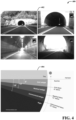
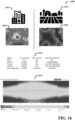
- FIG. 4 illustrates an example, non-limiting diagram of tunnel detection and determination of external light conditions in accordance with one or more embodiments described herein.
- image 402 and image 404 depict situations from which the context component 112 can determine if external light conditions meet a define threshold for darkness. More specifically, image 492 depicts four images of a tunnel (e.g., entrance to a tunnel, inside a tunnel, exit of a tunnel), from which the recognition component 108 can detect sources of light (e.g., light at the exit of a tunnel, light within a tunnel) or lack of light (e.g., lack of light at the entrance of a tunnel). Therefore, the context component 112 can utilize the determined illuminated areas to determine if the identification component 106 should be engaged for object detection.
- a tunnel e.g., entrance to a tunnel, inside a tunnel, exit of a tunnel
- sources of light e.g., light at the exit of a tunnel, light within a tunnel
- lack of light e.g., lack of light at the entrance of a tunnel
- the context component 112 can also predict approaching tunnels or ends of tunnels with GPS information as well as computer vision algorithms, and thus determine if object detection is desirable. For example, if vehicle one is driving in daylight, then the context component 112 can determine that object detection is not necessary to enable other vehicles to see objects on or alongside a road. However, if vehicle one is approaching a tunnel, the recognition component 108 can detect the entrance to the tunnel due to lack of illumination that occurs when entering a tunnel from daylight conditions. Therefore, the context component 112 can engage the identification component 106 to activate object detection upon entering the tunnel. Furthermore, the context component 112 can activate object detection for other situations of temporary darkness or lack of illumination (e.g., driving under a bridge, driving in a covered alley, driving in a dimly lit parking garage)
- the context component 112 can also use information on sunset times or twilight times to automatically activate object detection from the identification component 106. Furthermore, altitude, season of the year, time of day, or location of vehicle one can be utilized by the context component 112 to determine when object detection is desired. For example, vehicle one can utilize any suitable quipped sensors to determine the current angle of the sun, and thus decide to activate or deactivate object detection based on predefined settings As an example, the identification component 106 can be set to activate everyday after nautical twilight, depicted in image 404. Thus, if the context component 112 determines, via sensors, that the sun is 12 degrees below the horizon, the context component 112 can engage the identification component 106 to automatically activate object detection.
- FIG. 5 illustrates an example, non-limiting light pollution map for risk assessment in accordance with one or more embodiments described herein.
- Image 502 depicts a light pollution map of Sweden.
- the context component 112 can utilize light pollution maps in determining if external light conditions meet the defined threshold for darkness.
- the identification component 106 can be engaged to detect one or more objects on or alongside a road.
- light pollution maps can be utilized by the analysis component 110 to define how strict the risk assessment is for determining a risk level for the one or more identified objects. For example, by use of light pollution maps, the analysis component 110 can assign an object to be non-risky if detected in a city, but if detected in a countryside, the analysis component 110 can assign an object to be risky.
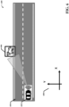
- FIG. 6 illustrates an example, non-limiting depiction of object detection by a vehicle in accordance with one or more embodiments described herein.
- a vehicle 602 can be driving on a road 604.
- vehicle 602 is an autonomous vehicle (AV).
- the identification component 106 of the system 100 that is onboard vehicle 602 can detect an object 606 near road 604.
- road 604 can be a two-lane road and object 606 can be a cow that is standing outside the opposite lane of vehicle 602.
- road 604 can be any type of road and comprise of any number of lanes.
- the identification component 106 can obtain information about the object 606 that can thus be used by the analysis component 110 for the risk assessment.
- the identification component 106 can identify, via the inference component 318, the type of object that is detected.
- the type of object can be a person, an animal, a vehicle, or a physical object (e.g., a pedestrian, a dog, a traffic cone).
- the identification component 106 can additionally identify if object 606 is moving and the direction in which it is moving. If object 606 is not moving, the identification component 106 can determine if object 606 is capable of moving.
- the identification component 106 can conclude that object 606 is not capable of moving. Conversely, if object 606 is not moving, and object 606 is identified to be a child, then the identification component 106 can conclude that object 606 is capable of moving. Furthermore, if object 606 is moving, the identification component 106 can determine if the movement of object 606 is predictable, unpredictable, or unknown. For example, if object 606 is a cyclist riding straight alongside a road, the movement can be determined to be predictable.
- the analysis component 110 can use such parameters (e.g., type of object, in movement, movement direction, type of movement, able to move, location) to assign a risk level to object 602.
- the analysis component 110 can, in response to a determination of the assigned risk level, engage the execution component 202 to notify other vehicles within the vicinity or alter driving of vehicle 602 if vehicle 602 is an AV (e.g., change lanes, slow down, speed up, turn on hazard lights, turn on high beam lights).
- FIG. 7 illustrates an example, non-limiting depiction of vehicle detection by a vehicle in accordance with one or more embodiments described herein.
- the identification component 106 can detect and identify, via inference component 318, an approaching vehicle 702 while vehicle 602 is driving on road 604.
- vehicle 702 is a non-autonomous vehicle (non-AV) and may lack adequate sensors or technology to detect objects at night.
- vehicle 702 can be any suitable type of vehicle (e.g., vehicle 702 can be an AV). If vehicle 702 is an AV, notifications or reports sent by vehicle 602 can be ignored, as vehicle 702 likely comprises suitable sensors to detect objects in less-illuminated environments. Depending on the autonomy level of vehicle 702, vehicle 702 can also request the driver to take control. If vehicle 702 is an AV but is being driven in manual mode, notifications or reports sent by vehicle 602 can be displayed to the driver.
- the approaching vehicle 702 can be approaching vehicle 602 from any direction and be driving in any lane of road 604.
- the identification component 106 can detect more than one vehicles within the vicinity.
- the recognition component 108 can, from the identified approaching vehicle 702, detect light to determine an illuminated area. For example, the recognition component 108 can determine an illuminated area resulting from the headlights of approaching vehicle 702.
- FIG. 8 illustrates an example, non-limiting depiction of vehicle light identification in accordance with one or more embodiments described herein.
- Depicted at 802 is an image from the perspective of vehicle 602, wherein there is approaching vehicle 702.
- the image can be taken, for example, from vehicle cameras 306 on the front of vehicle 602.
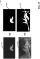
- the recognition component 108 can use, as depicted at 804, conversion of the image at 802 to black and white to determine the illuminated area caused by lights on the approaching vehicle 702.
- the illuminated area is visualized by the white areas on the image (e.g., headlights of vehicle 702, small area in front of vehicle 702).
- other methods besides conversion to black and white can be employed by the recognition component 108 to determine the illuminated area from lights on vehicle 702.
- FIG. 9 illustrates an example, non-limiting depiction of vehicle light identification in accordance with one or more embodiments described herein.
- the illuminated area (e.g., brightest area) covers a smaller region.
- the illuminated area (e.g., brightest area) covers a larger region.
- the identified illuminated area can be influenced by various factors. For example, activation of the lights or intensity of the lights set by the approaching vehicle 702 can affect the size of the determined illuminated area (e.g., if high beam lights are activated on the approaching vehicle, the illuminated area may be larger).
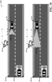
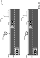
- FIG. 10 illustrates an example, non-limiting depiction of object and vehicle light detection by a vehicle in accordance with one or more embodiments described herein.
- the size of the illuminated area from approaching vehicle 702 affects the distance between detected objects and the illuminated area, based on location and light intensity of vehicle 702.
- approaching vehicle 702 is a distance d from object 606 with an illuminated area 1002 of length a.
- the illuminated area 1002 is smaller (e.g., due to low intensity lights used), and therefore object 606 may not be visible to the driver of vehicle 702 because object 606 is not within the illuminated area 1002.
- the analysis component 110 can perform a risk assessment on object 606 to determine a risk level to further determine if a notification is to be sent to vehicle 702 or other safety measures (e.g., slow down vehicle 602) are to be taken.
- approaching vehicle 702 is a distance d from object 606 with an illuminated area 1004 of length a.
- the illuminated area 10024 is larger (e.g., due to high intensity lights used), and therefore object 606 is likely visible to the driver of vehicle 702 because object 606 is within the illuminated area 1004.
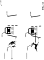
- the direction in which the object 606 is moving can be used by the analysis component 110 to determine a risk level associated with object 606. For example, if vehicle 1202 is approaching on road 1204 and pedestrians 1206 are detected such that pedestrians 1206 are moving away from the road, then the analysis component 110 may determine pedestrians 1206 to be less risky. As another example, if vehicle 1202 is approaching on road 1204 and deer 1208 is detected such that deer 1208 is running towards the road, then the analysis component 110 may determine deer 1208 to be very risky.
- the speed in which the objects are moving can also be considered in determining the risk level. For example, a pedestrian is walking at a slow pace towards the road can be less risky than a pedestrian running towards the road.
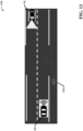
- the identification component 106 can detect a cyclist 1302 alongside the road that is outside the illuminated area from vehicle 702. Furthermore, the cyclist 106 can signal a turn to vehicle 602 (e.g., with hand gestures). For example, as depicted in FIG. 13 , cyclist 1302 is signaling a left turn across the road that will result in the cyclist 1302 passing across vehicle 702. However, due to lighting conditions, it can be assumed that the cyclist 1302 is not visible to vehicle 702, and therefore vehicle 702 is unaware that the cyclist 1302 will cross the road. Thus, the identification component 106 can detect and identify the direction the cyclist 1302 is planning to turn.
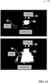
- FIG. 14 illustrates an example, non-limiting depiction of object and vehicle light detection by a vehicle in accordance with one or more embodiments described herein.
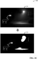
- Illuminated area 1402 from vehicle 702 comprises a small area that can be caused for various reasons, such as because low beam lights are utilized. Furthermore, object 606 is located far from illuminated area 1402, as shown by object 606 not located in the white region of the image that represents illuminated area 1402. Thus, the recognition component 108 can conclude that object 606 is not located within illuminated area 1402 and can assume that vehicle 702 is unable to see object 606.
- illuminated area 1404 from vehicle 702 comprises a larger area that can be caused for various reasons, such as high beam lights are utilized.
- object 606 is located within the white region of the image that represents illuminated area 1404.
- a section in front of object 606 lacks illumination, signaling that object 606 is casting a shadow from the lights of vehicle 702.
- the recognition component 108 can conclude that object 606 is located within illuminated area 1404 and can assume that vehicle 702 can see object 606.
- FIG. 15 illustrates an example, non-limiting depiction of brightness levels of an illumination area for risk assessment in accordance with one or more embodiments described herein.
- the recognition component 108 can define brightness levels of the illuminated area, wherein the brightness levels are based on light intensity. Brightness levels can be defined because light loses intensity as distance from the light source increases. For example, and as used herein, the recognition component 108 can utilize three levels of brightness to define the illuminated area. However, any suitable number of brightness levels can be utilized. Displayed in FIG. 15 are example vicinity images 312 from front-facing vehicle cameras 306 that are converted to black and white to illustrate an illuminated area from approaching vehicle 702. As an example, image 1502 displays level 1 brightness, image 1504 displays level 2 brightness, and image 1506 displays level 3 brightness, wherein level 1 brightness includes highest intensity light and level 3 includes lowest intensity light.
- level 1 brightness indicates a closer distance to vehicle 702 and level 3 brightness indicates a farther distance from vehicle 702.
- the risk assessment can determine the object to be riskier, as it is not visible to vehicle 702.
- image 1508 displays level 1 brightness
- image 1510 displays level 2 brightness
- image 1512 displays level 3 brightness. Depicted by image 1510, if the object is within the level 2 brightness but outside level 1 brightness, the risk assessment can conclude the object to be a medium risk.
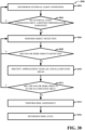
- the execution component 202 can determine the appropriate actions to execute in response to a determination of the risk level (e.g., activate dynamic bend lighting if medium risk, perform a lane change if high risk).
- FIG. 16 illustrates an example, non-limiting diagram of risk assessment parameters in accordance with one or more embodiments described herein.
- the analysis component 110 can consider various factors in the risk assessment to determine a risk level for one or more objects.
- information about the identified objects, learned by identification component 106 can be considered in the risk assessment.
- Depicted at 1610 are various examples of objects that can be detected by the identification component 106s.
- the object can be identified as a rock that is positioned in the middle of a road.
- the identification component 106 can further determine that the rock is not moving and is not capable of moving.
- the object can be identified as an animal.
- the identification component 106 can further determine if the animal is moving.
- the identification component 106 can also determine that the object is capable of moving and can exhibit unpredictable movement as it is an animal.
- the object can be identified as a person.
- the identification component 106 can further determine if the person is moving and the type of movement the person is exhibiting (e.g., predictable, unpredictable). The identification component 106 can also determine that the object is capable of moving as the object is a person. As even another example, the object can be identified as a vehicle. The identification component 106 can further determine if the vehicle is moving and the type of movement the person is exhibiting. The identification component 106 can also determine that the object is capable of moving as the object is a vehicle. As yet another example, the object can be unrecognized (e.g., an obstruction is causing challenges in identifying the object, the object is unknown). The identification component 106 can further determine if the unrecognized object is moving. The identification component 106 can also determine, based on the object being unrecognizable, that the object's capability of moving is unknown and the type of movement is unknown.
- the time of day can be considered in the risk assessment to determine a risk level for one or more objects.
- sun graph 1612 can be used to determine external light conditions and thus the analysis component 110 can use the determined external light conditions to decide how risky the one or more objects are (e.g., how visible the one or more objects are to an approaching vehicle).
- velocity of vehicle 702 can also affect which risk level is assigned to the one or more objects because velocity can affect the reaction time of a driver of vehicle 702. For example, if an object is detected near a road and vehicle 702 is driving at a high velocity, the analysis component 110 can determine that the object is very risky. Conversely, if the same object is detected but vehicle 702 is driving at a low velocity, the analysis component 110 can determine that the object is low risk or not risky.
- FIG. 17 illustrates an example, non-limiting depiction of other light source detection by a vehicle in accordance with one or more embodiments described herein.
- the risk assessment can further consider other light sources in the vicinity to determine risk levels associated with detected objects.
- the recognition component 108 can identify an illuminated area from the other light sources.
- the other light sources can be streetlights or lighting from other vehicles in the vicinity). Therefore, the recognition component 108 can identify if the one or more detected objects are within the illuminated area from the other light sources.
- depicted in 1702 is the perspective of vehicle 602, in which a streetlight is detected alongside a road.
- the recognition component 108 can convert image 1702 to black and white, as shown by 1704, to identify an illuminated area from the streetlight.
- an object 1802 can be detected near the road.
- the recognition component 108 can assume that object 1802 is not visible to approaching vehicles in the vicinity. For example, if vehicle 702 is approaching vehicle 602 from the opposite direction and object 1802 is not in the illuminated area from lights on vehicle 702 as well as from the streetlight, then it can be assumed that object 1802 is not visible to the driver of vehicle 702.
- FIG. 19 illustrates another example wherein object 1802 is located within the illuminated area from the streetlight. Thus, if vehicle 702 is approaching, the recognition component 108 can assume that object 1802 is within an illuminated area and therefore, likely to be visible to the driver of vehicle 702.
- the recognition component 108 can also assume object 1802 is visible to the driver of vehicle 702 even if object 1802 is not located within the illuminated area from lights on vehicle 702 because object 1802 is in the streetlight.
- the analysis component 110 can assign a risk level to object 1802.
- the recognition component 108 can determine the distance between an object and the illuminated area.
- the determined distance e.g., distance 1902, distance 1904 can be used as a parameter in the risk assessment to assign a risk level to the object.
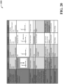
- FIG. 20 illustrates an example, non-limiting chart 2000 of risk assessment of detected objects in accordance with one or more embodiments described herein.
- weather conditions e.g., presence of ice on a road, rainfall, fog
- road types e.g., downhill roads, curved roads
- vehicle type e.g., sedan, semi-truck, van
- the risk assessment may assign a higher risk level.
- the risk assessment may assign a lower risk level due to the smaller size of the sedan and improved weather conditions. Therefore, there may be less potential for a hazardous collision to occur from a detected object.
- the identification component 106 can detect an animal that is moving with unpredictable movement. Furthermore, the animal can be close to the lane of the road and moving in a direction towards the road. Moreover, the vehicles (e.g., vehicle 602 and vehicle 702) can be located in a countryside and driving at night (e.g., determined in reference to image 404). No other lights sources are detected in scenario 1 and vehicle 702 is travelling at a high speed (e.g., over 70km/h). Based on these parameters of scenario 1, the analysis component 110 can assign a risk level of risky to the object.
- the analysis component 110 can assign a risk level of risky to the object.
- the identification component 106 can detect an animal that is not moving and can exhibit unpredictable movement. Furthermore, the animal can be close to the lane of the road. Moreover, the vehicles can be located in a city and driving at astronomical twilight. Another lights source is detected in scenario 2, however the object is located far from the other light source. Additionally, vehicle 702 is travelling at a moderate speed (e.g., 40km/h). Based on these parameters of scenario 2, the analysis component 110 can assign a risk level of risky to the object.
- the identification component 106 can detect a person that is moving and is exhibiting predictable movement. Furthermore, the person is far from the lane of the road and moving parallel with the road in the same direction as vehicle 702. Moreover, the vehicles can be located in a countryside and driving at nautical twilight. Another lights source is detected and the object is located near the other light source. Additionally, vehicle 702 is travelling at a low speed (e.g., 20km/h). Based on these parameters of scenario 3, the analysis component 110 can assign a risk level of non-risky to the object.
- the identification component 106 can detect a vehicle that is not moving and is pulled over close to a lane of the road. Because the vehicle is pulled over, the vehicle is exhibiting predictable movement. Moreover, the vehicles (e.g., vehicle 602, vehicle 702, and the detected vehicle) are located in a city and driving at night. Another lights source is detected and the object is located near the other light source. Additionally, vehicle 702 is travelling at a low speed (e.g., 20km/h). Based on these parameters of scenario 4, the analysis component 110 can assign a risk level of non-risky to the object.
- the vehicles e.g., vehicle 602, vehicle 702, and the detected vehicle
- the analysis component 110 can assign a risk level of non-risky to the object.
- FIG. 21 illustrates an example, non-limiting depiction of vehicle communication for object detection in accordance with one or more embodiments described herein.
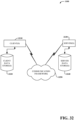
- the execution component 202 can transmit an electronic report to vehicle 702.
- the execution component 202 can transmit the electronic report through vehicle-to-vehicle (V2V) communication, as shown by 2102.
- V2V vehicle-to-vehicle
- vehicle 702 must be equipped with wireless communication devices that can support V2V communication (e.g., antennas, transceivers, communication protocols).
- the execution component 202 can also transmit the electronic report to vehicle 702 through a cloud system 2106.
- vehicle 702 must be equipped with GPS to allow vehicle 602 to know the location of vehicle 702 and internet connection to allow vehicle 702 to receive the report.
- Vehicle 602 can transmit the electronic report by first sending the report to the cloud system 2106.
- the report can include information on the detected object (e.g., location of the object, type of object, object movement) to inform the driver of vehicle 702 of the detected object.
- the location of vehicle 702 is also known, therefore, the report can also include a distance between the object and vehicle 702.
- the report can inform vehicle 702 if the object is moving closer or farther from the location of vehicle 702.
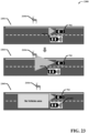
- FIG. 24 illustrates an example, non-limiting depiction of dynamic bend lighting for object detection by a vehicle in accordance with one or more embodiments described herein.
- tangible or “non-transitory” herein as applied to storage, memory or computer-readable media, are to be understood to exclude only propagating transitory signals per se as modifiers and do not relinquish rights to all standard storage, memory or computer-readable media that are not only propagating transitory signals per se.
- Computer-readable storage media can include, but are not limited to, quantum memories, or other tangible or non-transitory media which can be used to store desired information.
- tangible or non-transitory herein as applied to storage, memory or computer-readable media, are to be understood to exclude only propagating transitory signals per se as modifiers and do not relinquish rights to all standard storage, memory or computer-readable media that are not only propagating transitory signals per se.
- Computer-readable storage media can be accessed by one or more local or remote computing devices, e.g., via access requests, queries or other data retrieval protocols, for a variety of operations with respect to the information stored by the medium.
- Communications media typically embody computer-readable instructions, data structures, program modules or other structured or unstructured data in a data signal such as a modulated data signal, e.g., a carrier wave or other transport mechanism, and includes any information delivery or transport media.
- modulated data signal or signals refers to a signal that has one or more of its characteristics set or changed in such a manner as to encode information in one or more signals.
- communication media include wired media, such as a wired network or direct-wired connection, and wireless media such as acoustic, RF, infrared and other wireless media.
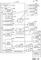
- the example environment 3100 for implementing various embodiments of the aspects described herein includes a computer 3102, the computer 3102 including a processing unit 3104, a system memory 3106 and a system bus 3108.
- the system bus 3108 couples system components including, but not limited to, the system memory 3106 to the processing unit 3104.
- the processing unit 3104 can be any of various commercially available processors. Dual microprocessors and other multi-processor architectures can also be employed as the processing unit 3104.
- the system bus 3108 can be any of several types of bus structure that can further interconnect to a memory bus (with or without a memory controller), a peripheral bus, and a local bus using any of a variety of commercially available bus architectures.
- the system memory 3106 includes ROM 3110 and RAM 3112.
- a basic input/output system (BIOS) can be stored in a non-volatile memory such as ROM, erasable programmable read only memory (EPROM), EEPROM, which BIOS contains the basic routines that help to transfer information between elements within the computer 3102, such as during startup.
- the RAM 3112 can also include a high-speed RAM such as static RAM for caching data.
- the computer 3102 further includes an internal hard disk drive (HDD) 3114 (e.g., EIDE, SATA), one or more external storage devices 3116 (e.g., a magnetic floppy disk drive (FDD) 3116, a memory stick or flash drive reader, a memory card reader, etc.) and a drive 3120, e.g., such as a solid state drive, an optical disk drive, which can read or write from a disk 3122, such as a CD-ROM disc, a DVD, a BD, etc.
- HDD internal hard disk drive
- FDD magnetic floppy disk drive
- a memory stick or flash drive reader e.g., a memory stick or flash drive reader, a memory card reader, etc.
- a drive 3120 e.g., such as a solid state drive, an optical disk drive, which can read or write from a disk 3122, such as a CD-ROM disc, a DVD, a BD, etc.
- disk 3122 would not be included,
- the internal HDD 3114 is illustrated as located within the computer 3102, the internal HDD 3114 can also be configured for external use in a suitable chassis (not shown). Additionally, while not shown in environment 3100, a solid state drive (SSD) could be used in addition to, or in place of, an HDD 3114.
- the HDD 3114, external storage device(s) 3116 and drive 3120 can be connected to the system bus 3108 by an HDD interface 3124, an external storage interface 3126 and a drive interface 3128, respectively.
- the interface 3124 for external drive implementations can include at least one or both of Universal Serial Bus (USB) and Institute of Electrical and Electronics Engineers (IEEE) 1394 interface technologies. Other external drive connection technologies are within contemplation of the embodiments described herein.
- the drives and their associated computer-readable storage media provide nonvolatile storage of data, data structures, computer-executable instructions, and so forth.
- the drives and storage media accommodate the storage of any data in a suitable digital format.
- computer-readable storage media refers to respective types of storage devices, it should be appreciated by those skilled in the art that other types of storage media which are readable by a computer, whether presently existing or developed in the future, could also be used in the example operating environment, and further, that any such storage media can contain computer-executable instructions for performing the methods described herein.
- a number of program modules can be stored in the drives and RAM 3112, including an operating system 3130, one or more application programs 3132, other program modules 3134 and program data 3136. All or portions of the operating system, applications, modules, or data can also be cached in the RAM 3112.
- the systems and methods described herein can be implemented utilizing various commercially available operating systems or combinations of operating systems.
- Computer 3102 can optionally comprise emulation technologies.
- a hypervisor (not shown) or other intermediary can emulate a hardware environment for operating system 3130, and the emulated hardware can optionally be different from the hardware illustrated in FIG. 31 .
- operating system 3130 can comprise one virtual machine (VM) of multiple VMs hosted at computer 3102.
- VM virtual machine
- operating system 3130 can provide runtime environments, such as the Java runtime environment or the .NET framework, for applications 3132. Runtime environments are consistent execution environments that allow applications 3132 to run on any operating system that includes the runtime environment.
- operating system 3130 can support containers, and applications 3132 can be in the form of containers, which are lightweight, standalone, executable packages of software that include, e.g., code, runtime, system tools, system libraries and settings for an application.
- computer 3102 can be enable with a security module, such as a trusted processing module (TPM).
- TPM trusted processing module
- boot components hash next in time boot components, and wait for a match of results to secured values, before loading a next boot component.
- This process can take place at any layer in the code execution stack of computer 3102, e.g., applied at the application execution level or at the operating system (OS) kernel level, thereby enabling security at any level of code execution.
- OS operating system
- a monitor 3146 or other type of display device can be also connected to the system bus 3108 via an interface, such as a video adapter 3148.
- a computer typically includes other peripheral output devices (not shown), such as speakers, printers, etc.
- the computer 3102 can be operable to communicate with any wireless devices or entities operatively disposed in wireless communication, e.g., a printer, scanner, desktop or portable computer, portable data assistant, communications satellite, any piece of equipment or location associated with a wirelessly detectable tag (e.g., a kiosk, news stand, store shelf, etc.), and telephone.
- any wireless devices or entities operatively disposed in wireless communication e.g., a printer, scanner, desktop or portable computer, portable data assistant, communications satellite, any piece of equipment or location associated with a wirelessly detectable tag (e.g., a kiosk, news stand, store shelf, etc.), and telephone.
- This can include Wireless Fidelity (Wi-Fi) and BLUETOOTH ® wireless technologies.
- the communication can be a predefined structure as with a conventional network or simply an ad hoc communication between at least two devices.
- Computer readable program instructions for carrying out operations of the present invention can be assembler instructions, instruction-set-architecture (ISA) instructions, machine instructions, machine dependent instructions, microcode, firmware instructions, state-setting data, configuration data for integrated circuitry, or either source code or object code written in any combination of one or more programming languages, including an object oriented programming language such as Smalltalk, C++, or the like, and procedural programming languages, such as the "C" programming language or similar programming languages.
- the computer readable program instructions can execute entirely on the user's computer, partly on the user's computer, as a stand-alone software package, partly on the user's computer and partly on a remote computer or entirely on the remote computer or server.
- a system comprising: a processor that executes computer-executable components stored in a non-transitory computer-readable memory, the computer-executable components comprising: an identification component that detects one or more objects on or alongside a road; a recognition component that detects light from an approaching vehicle to determine an illuminated area, and determines if the one or more objects are located in the illuminated area; and an analysis component that performs, in response to a determination that the one or more objects are not located in the illuminated area, a risk assessment on the one or more objects based on parameters of the one or more objects.
- Clause 2 The system of any preceding clause, wherein the parameters of the one or more objects comprise object type, movement, ability to move, or location.
- Clause 3 The system of any preceding clause, wherein the analysis component determines a risk level of the one or more objects based on the risk assessment.
- Clause 4 The system of any preceding clause, wherein the risk assessment determines the risk level of the one or more objects based on GPS data, light pollution maps, time of day, season, latitude, speed of the vehicle, type of the vehicle, road conditions, or environment conditions.
- Clause 6 The system of any preceding clause, further comprising an execution component that changes light intensity of headlights on the approaching vehicle in response to a determination of the risk level of the one or more objects.
- Clause 7 The system of any preceding clause, wherein the execution component changes headlight angles on the approaching vehicle based on location of the one or more objects.
- Clause 8 The system of any preceding clause, wherein the execution component transmits, in response to a determination of the risk level of the one or more objects, an electronic notification to the approaching vehicle or other vehicles within a defined range.
- Clause 9 The system of any preceding clause, further comprising a context component that determines if external light conditions meet a defined threshold of darkness.
- Clause 10 The system of any preceding clause, wherein the execution component performs a lane change, increases speed, or decreases speed of the vehicle in response to a determination of the risk level of the one or more objects.
- Clause 11 The system of any preceding clause, wherein the recognition component identifies an entrance or exit of a tunnel, and wherein the context component determines if light conditions in the tunnel meet the defined threshold of darkness.
- Clause 12 The system of any preceding clause, wherein the execution component activates hazard lights on the approaching vehicle in response to a determination of the risk level of the one or more objects.
- a computer-implemented method comprising: detecting one or more objects on or alongside a road; detecting light from an approaching vehicle to determine an illuminated area, and determining if the one or more objects are located in the illuminated area; and performing, in response to a determination that the one or more objects are not located in the illuminated area, a risk assessment on the one or more objects based on parameters of the one or more objects.
Landscapes
- Engineering & Computer Science (AREA)
- Mechanical Engineering (AREA)
- Physics & Mathematics (AREA)
- General Physics & Mathematics (AREA)
- Automation & Control Theory (AREA)
- Transportation (AREA)
- Multimedia (AREA)
- Theoretical Computer Science (AREA)
- Mathematical Physics (AREA)
- Traffic Control Systems (AREA)
Applications Claiming Priority (1)
| Application Number | Priority Date | Filing Date | Title |
|---|---|---|---|
| US18/543,418 US20250196852A1 (en) | 2023-12-18 | 2023-12-18 | Object detection in darkness during vehicle operation |
Publications (1)
| Publication Number | Publication Date |
|---|---|
| EP4576040A1 true EP4576040A1 (de) | 2025-06-25 |
Family
ID=91950151
Family Applications (1)
| Application Number | Title | Priority Date | Filing Date |
|---|---|---|---|
| EP24188562.3A Pending EP4576040A1 (de) | 2023-12-18 | 2024-07-15 | Objekterkennung im dunkeln beim fahrzeugbetrieb |
Country Status (3)
| Country | Link |
|---|---|
| US (1) | US20250196852A1 (de) |
| EP (1) | EP4576040A1 (de) |
| CN (1) | CN120171534A (de) |
Citations (3)
| Publication number | Priority date | Publication date | Assignee | Title |
|---|---|---|---|---|
| US20160152182A1 (en) * | 2014-11-28 | 2016-06-02 | Fujitsu Limited | Driving support device and driving support method |
| US20180229587A1 (en) * | 2017-02-16 | 2018-08-16 | GM Global Technology Operations LLC | Vehicle environment imaging systems and methods |
| US20210213869A1 (en) * | 2020-01-14 | 2021-07-15 | Qualcomm Incorporated | Collaborative Vehicle Headlight Directing |
Family Cites Families (5)
| Publication number | Priority date | Publication date | Assignee | Title |
|---|---|---|---|---|
| DE102014221647A1 (de) * | 2014-10-24 | 2016-04-28 | Ford Global Technologies, Llc | Fahrzeugscheinwerfersystem mit adaptiver Lichtverteilung |
| US9731645B1 (en) * | 2016-04-07 | 2017-08-15 | Valeo North America, Inc. | Cooperative adaptive lighting system using vehicle to target or object communication |
| DE102018200025A1 (de) * | 2018-01-02 | 2019-07-04 | Ford Global Technologies, Llc | Fahrzeugbeleuchtung |
| US11325524B2 (en) * | 2020-01-14 | 2022-05-10 | Qualcomm Incorporated | Collaborative vehicle headlight directing |
| JP7567772B2 (ja) * | 2021-12-27 | 2024-10-16 | トヨタ自動車株式会社 | 車両灯火制御装置 |
-
2023
- 2023-12-18 US US18/543,418 patent/US20250196852A1/en active Pending
-
2024
- 2024-07-15 EP EP24188562.3A patent/EP4576040A1/de active Pending
- 2024-08-21 CN CN202411149771.7A patent/CN120171534A/zh active Pending
Patent Citations (3)
| Publication number | Priority date | Publication date | Assignee | Title |
|---|---|---|---|---|
| US20160152182A1 (en) * | 2014-11-28 | 2016-06-02 | Fujitsu Limited | Driving support device and driving support method |
| US20180229587A1 (en) * | 2017-02-16 | 2018-08-16 | GM Global Technology Operations LLC | Vehicle environment imaging systems and methods |
| US20210213869A1 (en) * | 2020-01-14 | 2021-07-15 | Qualcomm Incorporated | Collaborative Vehicle Headlight Directing |
Also Published As
| Publication number | Publication date |
|---|---|
| CN120171534A (zh) | 2025-06-20 |
| US20250196852A1 (en) | 2025-06-19 |
Similar Documents
| Publication | Publication Date | Title |
|---|---|---|
| JP7499256B2 (ja) | ドライバの挙動を分類するためのシステムおよび方法 | |
| US12351152B2 (en) | Emergency braking for autonomous vehicles | |
| US10077007B2 (en) | Sidepod stereo camera system for an autonomous vehicle | |
| US12097892B2 (en) | System and method for providing an RNN-based human trust model | |
| CN112758013B (zh) | 车辆的显示装置和显示方法 | |
| JP7318692B2 (ja) | 適応可能な後突警報のためのシステムと方法 | |
| JP7637796B2 (ja) | 車両ナビゲーション中の光干渉検出 | |
| US11663860B2 (en) | Dynamic and variable learning by determining and using most-trustworthy inputs | |
| CN108604413A (zh) | 显示装置的控制方法及显示装置 | |
| US20240326863A1 (en) | Detection and avoidance of car dooring of cyclists | |
| US20240286609A1 (en) | Animal collision aware planning systems and methods for autonomous vehicles | |
| US20240359624A1 (en) | Mitigation of accidents due to glare from sun or headlights | |
| CN115384545B (zh) | 控制方法和装置 | |
| CN120840659A (zh) | 车辆控制策略的获取方法、装置、介质、设备 | |
| KR20230067799A (ko) | 환경 조건에 따라 적어도 하나 이상의 가상 차선을 표시하는 장치의 제어 방법 및 장치 | |
| EP4576040A1 (de) | Objekterkennung im dunkeln beim fahrzeugbetrieb | |
| US20240192360A1 (en) | Driving assistance system and driving assistance method | |
| US20260014989A1 (en) | Artificially intelligent assistance of hazardous overtaking initiatives | |
| RU2809334C1 (ru) | Беспилотное транспортное средство и способ управления его движением | |
| US12485904B2 (en) | Vehicle tire area control | |
| US20260073794A1 (en) | Systems and methods for preventing unsafe driving behavior | |
| RU2814813C1 (ru) | Устройство и способ для отслеживания объектов | |
| RU2806452C1 (ru) | Устройство и способ для определения объектов | |
| US20250273072A1 (en) | System and method for mitigating vehicle collision with a bicycle | |
| US20240264291A1 (en) | Apparatus and method controlling the same |
Legal Events
| Date | Code | Title | Description |
|---|---|---|---|
| PUAI | Public reference made under article 153(3) epc to a published international application that has entered the european phase |
Free format text: ORIGINAL CODE: 0009012 |
|
| STAA | Information on the status of an ep patent application or granted ep patent |
Free format text: STATUS: THE APPLICATION HAS BEEN PUBLISHED |
|
| AK | Designated contracting states |
Kind code of ref document: A1 Designated state(s): AL AT BE BG CH CY CZ DE DK EE ES FI FR GB GR HR HU IE IS IT LI LT LU LV MC ME MK MT NL NO PL PT RO RS SE SI SK SM TR |
|
| STAA | Information on the status of an ep patent application or granted ep patent |
Free format text: STATUS: REQUEST FOR EXAMINATION WAS MADE |
|
| 17P | Request for examination filed |
Effective date: 20260102 |
|
| STAA | Information on the status of an ep patent application or granted ep patent |
Free format text: STATUS: THE APPLICATION IS DEEMED TO BE WITHDRAWN |