EP4576076A1 - Audiokodierung mit einem frequenzbereichsprozessor und einem zeitbereichprozessor - Google Patents
Audiokodierung mit einem frequenzbereichsprozessor und einem zeitbereichprozessor Download PDFInfo
- Publication number
- EP4576076A1 EP4576076A1 EP25174210.2A EP25174210A EP4576076A1 EP 4576076 A1 EP4576076 A1 EP 4576076A1 EP 25174210 A EP25174210 A EP 25174210A EP 4576076 A1 EP4576076 A1 EP 4576076A1
- Authority
- EP
- European Patent Office
- Prior art keywords
- spectral
- audio signal
- frequency
- processor
- encoded
- Prior art date
- Legal status (The legal status is an assumption and is not a legal conclusion. Google has not performed a legal analysis and makes no representation as to the accuracy of the status listed.)
- Pending
Links
Images










Classifications
-
- G—PHYSICS
- G10—MUSICAL INSTRUMENTS; ACOUSTICS
- G10L—SPEECH ANALYSIS TECHNIQUES OR SPEECH SYNTHESIS; SPEECH RECOGNITION; SPEECH OR VOICE PROCESSING TECHNIQUES; SPEECH OR AUDIO CODING OR DECODING
- G10L19/00—Speech or audio signals analysis-synthesis techniques for redundancy reduction, e.g. in vocoders; Coding or decoding of speech or audio signals, using source filter models or psychoacoustic analysis
- G10L19/02—Speech or audio signals analysis-synthesis techniques for redundancy reduction, e.g. in vocoders; Coding or decoding of speech or audio signals, using source filter models or psychoacoustic analysis using spectral analysis, e.g. transform vocoders or subband vocoders
- G10L19/028—Noise substitution, i.e. substituting non-tonal spectral components by noisy source
-
- G—PHYSICS
- G10—MUSICAL INSTRUMENTS; ACOUSTICS
- G10L—SPEECH ANALYSIS TECHNIQUES OR SPEECH SYNTHESIS; SPEECH RECOGNITION; SPEECH OR VOICE PROCESSING TECHNIQUES; SPEECH OR AUDIO CODING OR DECODING
- G10L19/00—Speech or audio signals analysis-synthesis techniques for redundancy reduction, e.g. in vocoders; Coding or decoding of speech or audio signals, using source filter models or psychoacoustic analysis
- G10L19/02—Speech or audio signals analysis-synthesis techniques for redundancy reduction, e.g. in vocoders; Coding or decoding of speech or audio signals, using source filter models or psychoacoustic analysis using spectral analysis, e.g. transform vocoders or subband vocoders
- G10L19/032—Quantisation or dequantisation of spectral components
-
- G—PHYSICS
- G10—MUSICAL INSTRUMENTS; ACOUSTICS
- G10L—SPEECH ANALYSIS TECHNIQUES OR SPEECH SYNTHESIS; SPEECH RECOGNITION; SPEECH OR VOICE PROCESSING TECHNIQUES; SPEECH OR AUDIO CODING OR DECODING
- G10L19/00—Speech or audio signals analysis-synthesis techniques for redundancy reduction, e.g. in vocoders; Coding or decoding of speech or audio signals, using source filter models or psychoacoustic analysis
- G10L19/04—Speech or audio signals analysis-synthesis techniques for redundancy reduction, e.g. in vocoders; Coding or decoding of speech or audio signals, using source filter models or psychoacoustic analysis using predictive techniques
- G10L19/06—Determination or coding of the spectral characteristics, e.g. of the short-term prediction coefficients
-
- G—PHYSICS
- G10—MUSICAL INSTRUMENTS; ACOUSTICS
- G10L—SPEECH ANALYSIS TECHNIQUES OR SPEECH SYNTHESIS; SPEECH RECOGNITION; SPEECH OR VOICE PROCESSING TECHNIQUES; SPEECH OR AUDIO CODING OR DECODING
- G10L19/00—Speech or audio signals analysis-synthesis techniques for redundancy reduction, e.g. in vocoders; Coding or decoding of speech or audio signals, using source filter models or psychoacoustic analysis
- G10L19/04—Speech or audio signals analysis-synthesis techniques for redundancy reduction, e.g. in vocoders; Coding or decoding of speech or audio signals, using source filter models or psychoacoustic analysis using predictive techniques
- G10L19/16—Vocoder architecture
- G10L19/18—Vocoders using multiple modes
-
- G—PHYSICS
- G10—MUSICAL INSTRUMENTS; ACOUSTICS
- G10L—SPEECH ANALYSIS TECHNIQUES OR SPEECH SYNTHESIS; SPEECH RECOGNITION; SPEECH OR VOICE PROCESSING TECHNIQUES; SPEECH OR AUDIO CODING OR DECODING
- G10L19/00—Speech or audio signals analysis-synthesis techniques for redundancy reduction, e.g. in vocoders; Coding or decoding of speech or audio signals, using source filter models or psychoacoustic analysis
- G10L19/04—Speech or audio signals analysis-synthesis techniques for redundancy reduction, e.g. in vocoders; Coding or decoding of speech or audio signals, using source filter models or psychoacoustic analysis using predictive techniques
- G10L19/26—Pre-filtering or post-filtering
- G10L19/265—Pre-filtering, e.g. high frequency emphasis prior to encoding
-
- G—PHYSICS
- G10—MUSICAL INSTRUMENTS; ACOUSTICS
- G10L—SPEECH ANALYSIS TECHNIQUES OR SPEECH SYNTHESIS; SPEECH RECOGNITION; SPEECH OR VOICE PROCESSING TECHNIQUES; SPEECH OR AUDIO CODING OR DECODING
- G10L19/00—Speech or audio signals analysis-synthesis techniques for redundancy reduction, e.g. in vocoders; Coding or decoding of speech or audio signals, using source filter models or psychoacoustic analysis
- G10L19/02—Speech or audio signals analysis-synthesis techniques for redundancy reduction, e.g. in vocoders; Coding or decoding of speech or audio signals, using source filter models or psychoacoustic analysis using spectral analysis, e.g. transform vocoders or subband vocoders
-
- G—PHYSICS
- G10—MUSICAL INSTRUMENTS; ACOUSTICS
- G10L—SPEECH ANALYSIS TECHNIQUES OR SPEECH SYNTHESIS; SPEECH RECOGNITION; SPEECH OR VOICE PROCESSING TECHNIQUES; SPEECH OR AUDIO CODING OR DECODING
- G10L19/00—Speech or audio signals analysis-synthesis techniques for redundancy reduction, e.g. in vocoders; Coding or decoding of speech or audio signals, using source filter models or psychoacoustic analysis
- G10L19/04—Speech or audio signals analysis-synthesis techniques for redundancy reduction, e.g. in vocoders; Coding or decoding of speech or audio signals, using source filter models or psychoacoustic analysis using predictive techniques
-
- G—PHYSICS
- G10—MUSICAL INSTRUMENTS; ACOUSTICS
- G10L—SPEECH ANALYSIS TECHNIQUES OR SPEECH SYNTHESIS; SPEECH RECOGNITION; SPEECH OR VOICE PROCESSING TECHNIQUES; SPEECH OR AUDIO CODING OR DECODING
- G10L19/00—Speech or audio signals analysis-synthesis techniques for redundancy reduction, e.g. in vocoders; Coding or decoding of speech or audio signals, using source filter models or psychoacoustic analysis
- G10L19/04—Speech or audio signals analysis-synthesis techniques for redundancy reduction, e.g. in vocoders; Coding or decoding of speech or audio signals, using source filter models or psychoacoustic analysis using predictive techniques
- G10L19/16—Vocoder architecture
- G10L19/18—Vocoders using multiple modes
- G10L19/20—Vocoders using multiple modes using sound class specific coding, hybrid encoders or object based coding
-
- G—PHYSICS
- G10—MUSICAL INSTRUMENTS; ACOUSTICS
- G10L—SPEECH ANALYSIS TECHNIQUES OR SPEECH SYNTHESIS; SPEECH RECOGNITION; SPEECH OR VOICE PROCESSING TECHNIQUES; SPEECH OR AUDIO CODING OR DECODING
- G10L19/00—Speech or audio signals analysis-synthesis techniques for redundancy reduction, e.g. in vocoders; Coding or decoding of speech or audio signals, using source filter models or psychoacoustic analysis
- G10L19/04—Speech or audio signals analysis-synthesis techniques for redundancy reduction, e.g. in vocoders; Coding or decoding of speech or audio signals, using source filter models or psychoacoustic analysis using predictive techniques
- G10L19/16—Vocoder architecture
- G10L19/18—Vocoders using multiple modes
- G10L19/24—Variable rate codecs, e.g. for generating different qualities using a scalable representation such as hierarchical encoding or layered encoding
-
- G—PHYSICS
- G10—MUSICAL INSTRUMENTS; ACOUSTICS
- G10L—SPEECH ANALYSIS TECHNIQUES OR SPEECH SYNTHESIS; SPEECH RECOGNITION; SPEECH OR VOICE PROCESSING TECHNIQUES; SPEECH OR AUDIO CODING OR DECODING
- G10L21/00—Speech or voice signal processing techniques to produce another audible or non-audible signal, e.g. visual or tactile, in order to modify its quality or its intelligibility
- G10L21/02—Speech enhancement, e.g. noise reduction or echo cancellation
- G10L21/038—Speech enhancement, e.g. noise reduction or echo cancellation using band spreading techniques
Definitions
- the present invention relates to audio signal encoding and decoding and, in particular, to audio signal processing using parallel frequency domain and time domain encoder/decoder processors.
- the perceptual coding of audio signals for the purpose of data reduction for efficient storage or transmission of these signals is a widely used practice.
- the employed coding leads to a reduction of audio quality that often is primarily caused by a limitation at the encoder side of the audio signal bandwidth to be transmitted.
- the audio signal is low-pass filtered such that no spectral waveform content remains above a certain pre-determined cut-off frequency.
- BWE Bandwidth Extension
- SBR Spectral Band Replication
- TD-BWE Time Domain Bandwidth Extension
- time domain/frequency domain coding concepts exist such as concepts known under the term AMR-WB+ or USAC.
- the time domain encoder is selected for useful signals to be encoded in the time domain such as speech signals and the frequency domain encoder is selected for non-speech signals, music signals, etc.
- the prior art frequency domain encoders have a reduced accuracy and, therefore, a reduced audio quality due to the fact that such prominent harmonics can only be separately parametrically encoded or are eliminated at all in the encoding/decoding process.
- the time domain encoding/decoding branch additionally relies on the bandwidth extension which also parametrically encodes an upper frequency range while a lower frequency range is typically encoded using an ACELP or any other CELP related coder, for example a speech coder.
- This bandwidth extension functionality increases the bitrate efficiency but, on the other hand, introduces further inflexibility due to the fact that both encoding branches, i.e., the frequency domain encoding branch and the time domain encoding branch are band limited due to the bandwidth extension procedure or spectral band replication procedure operating above a certain crossover frequency substantially lower than the maximum frequency included in the input audio signal.
- WO 2011/048117 A1 discloses an audio signal decoder for providing a decoded representation of an audio content on the basis of an encoded representation of the audio content comprises a transform domain path configured to obtain a time-domain representation of a portion of the audio content encoded in a transform-domain mode on the basis of a first set of spectral coefficients, a representation of an aliasing-cancellation stimulus signal and a plurality of linear-prediction-domain parameters.
- the transform domain path comprises a spectrum processor configured to apply a spectrum shaping to the first set of spectral coefficients in dependence on at least a subset of the linear-prediction-domain parameters, to obtain a spectrally-shaped version of the first set of spectral coefficients.
- the transform domain path comprises a first frequency-domain-to-time-domain converter configured to obtain a time-domain representation of the audio content on the basis of the spectrally-shaped version of the first set of spectral coefficients.
- the transform domain path comprises an aliasing-cancellation stimulus filter configured to filter the aliasing-cancellation stimulus signal in dependence on at least a subset of the linear-prediction-domain parameters, to derive an aliasing-cancellation synthesis signal from the aliasing-cancellation stimulus signal.
- the transform domain path also comprises a combiner configured to combine the time-domain representation of the audio content with the aliasing-cancellation synthesis signal, or a post-processed version thereof, to obtain an aliasing reduced time-domain signal.
- An encoder comprises a spectral domain encoding path and a time domain encoding path.
- the spectral domain encoding path operates using a psychoacoustic model calculating scale factors and a quantizer for quantizing
- US 2013/030798 A1 discloses an encoder and decoder for processing an audio signal including generic audio and speech frames.
- two encoders are utilized by the speech coder, and two decoders are utilized by the speech decoder.
- the two encoders and decoders are utilized to process speech and non-speech (generic audio) respectively.
- speech and non-speech generator audio
- parameters that are needed by the speech decoder for decoding frame of speech are generated by processing the preceding generic audio (non-speech) frame for the necessary parameters.
- WO 2009/029037 A1 discloses method for spectrum recovery in spectral decoding of an audio signal, which comprises obtaining of an initial set of spectral coefficients representing the audio signal, and determining a transition frequency.
- the transition frequency is adapted to a spectral content of the audio signal.
- Spectral holes in the initial set of spectral coefficients below the transition frequency are noise filled and the initial set of spectral coefficients are bandwidth extended above the transition frequency.
- Decoders and encoders being arranged for performing part of or the entire method are also illustrated.
- the present invention is based on the finding that a time domain encoding/decoding processor can be combined with a frequency domain encoding/decoding processor having a gap filling functionality but this gap filling functionality for filling spectral holes is operated over the whole band of the audio signal or at least above a certain gap filling frequency.
- the frequency domain encoding/decoding processor is particularly in the position to perform accurate or wave form or spectral value encoding/decoding up to the maximum frequency and not only until a crossover frequency.
- the full-band capability of the frequency domain encoder for encoding with the high resolution allows an integration of the gap filling functionality into the frequency domain encoder.
- the problems related to the separation of the bandwidth extension on the one hand and the core coding on the other hand can be addressed and overcome by performing the bandwidth extension in the same spectral domain in which the core decoder operates. Therefore, a full rate core decoder is provided which encodes and decodes the full audio signal range. This does not require the need for a downsampler on the encoder side and an upsampler on the decoder side. Instead, the whole processing is performed in the full sampling rate or full-bandwidth domain.
- the audio signal is analyzed in order to find a first set of first spectral portions which has to be encoded with a high resolution, where this first set of first spectral portions may include, in an embodiment, tonal portions of the audio signal.
- this first set of first spectral portions may include, in an embodiment, tonal portions of the audio signal.
- non-tonal or noisy components in the audio signal constituting a second set of second spectral portions are parametrically encoded with low spectral resolution.
- the encoded audio signal then only requires the first set of first spectral portions encoded in a waveform-preserving manner with a high spectral resolution and, additionally, the second set of second spectral portions encoded parametrically with a low resolution using frequency "tiles" sourced from the first set.
- the core decoder which is a full-band decoder, reconstructs the first set of first spectral portions in a waveform-preserving manner, i.e., without any knowledge that there is any additional frequency regeneration.
- the so generated spectrum has a lot of spectral gaps.
- These gaps are subsequently filled with the inventive Intelligent Gap Filling (IGF) technology by using a frequency regeneration applying parametric data on the one hand and using a source spectral range, i.e., first spectral portions reconstructed by the full rate audio decoder on the other hand.
- IGF Intelligent Gap Filling
- spectral portions which are reconstructed by noise filling only rather than bandwidth replication or frequency tile filling, constitute a third set of third spectral portions. Due to the fact that the coding concept operates in a single domain for the core coding/decoding on the one hand and the frequency regeneration on the other hand, the IGF is not only restricted to fill up a higher frequency range but can fill up lower frequency ranges, either by noise filling without frequency regeneration or by frequency regeneration using a frequency tile at a different frequency range.
- an information on spectral energies, an information on individual energies or an individual energy information, an information on a survive energy or a survive energy information, an information a tile energy or a tile energy information, or an information on a missing energy or a missing energy information may comprise not only an energy value, but also an (e.g. absolute) amplitude value, a level value or any other value, from which a final energy value can be derived.
- the information on an energy may e.g. comprise the energy value itself, and/or a value of a level and/or of an amplitude and/or of an absolute amplitude.
- a further aspect is based on the finding that the correlation situation is not only important for the source range but is also important for the target range. Furthermore, the present invention acknowledges the situation that different correlation situations can occur in the source range and the target range.
- the situation can be that the low frequency band comprising the speech signal with a small number of overtones is highly correlated in the left channel and the right channel, when the speaker is placed in the middle.
- the high frequency portion can be strongly uncorrelated due to the fact that there might be a different high frequency noise on the left side compared to another high frequency noise or no high frequency noise on the right side.
- parametric data for a reconstruction band or, generally, for the second set of second spectral portions which have to be reconstructed using a first set of first spectral portions is calculated to identify either a first or a second different two-channel representation for the second spectral portion or, stated differently, for the reconstruction band.
- a two-channel identification is, therefore calculated for the second spectral portions, i.e., for the portions, for which, additionally, energy information for reconstruction bands is calculated.
- a frequency regenerator on the decoder side regenerates a second spectral portion depending on a first portion of the first set of first spectral portions, i.e., the source range and parametric data for the second portion such as spectral envelope energy information or any other spectral envelope data and, additionally, dependent on the two-channel identification for the second portion, i.e., for this reconstruction band under reconsideration.
- the two-channel identification is preferably transmitted as a flag for each reconstruction band and this data is transmitted from an encoder to a decoder and the decoder then decodes the core signal as indicated by preferably calculated flags for the core bands. Then, in an implementation, the core signal is stored in both stereo representations (e.g. left/right and mid/side) and, for the IGF frequency tile filling, the source tile representation is chosen to fit the target tile representation as indicated by the two-channel identification flags for the intelligent gap filling or reconstruction bands, i.e., for the target range.
- this procedure not only works for stereo signals, i.e., for a left channel and the right channel but also operates for multi-channel signals.
- multi-channel signals several pairs of different channels can be processed in that way such as a left and a right channel as a first pair, a left surround channel and a right surround as the second pair and a center channel and an LFE channel as the third pair.
- Other pairings can be determined for higher output channel formats such as 7.1, 11.1 and so on.
- a further aspect is based on the finding that the audio quality of the reconstructed signal can be improved through IGF since the whole spectrum is accessible to the core encoder so that, for example, perceptually important tonal portions in a high spectral range can still be encoded by the core coder rather than parametric substitution.
- a gap filling operation using frequency tiles from a first set of first spectral portions which is, for example, a set of tonal portions typically from a lower frequency range, but also from a higher frequency range if available, is performed.
- the spectral portions from the first set of spectral portions located in the reconstruction band are not further post-processed by e.g. the spectral envelope adjustment.
- the envelope information is a full-band envelope information accounting for the energy of the first set of first spectral portions in the reconstruction band and the second set of second spectral portions in the same reconstruction band, where the latter spectral values in the second set of second spectral portions are indicated to be zero and are, therefore, not encoded by the core encoder, but are parametrically coded with low resolution energy information.
- a further aspect is based on the finding that certain impairments in audio quality can be remedied by applying a signal adaptive frequency tile filling scheme.
- an analysis on the encoder-side is performed in order to find out the best matching source region candidate for a certain target region.
- a matching information identifying for a target region a certain source region together with optionally some additional information is generated and transmitted as side information to the decoder.
- the decoder then applies a frequency tile filling operation using the matching information.
- the decoder reads the matching information from the transmitted data stream or data file and accesses the source region identified for a certain reconstruction band and, if indicated in the matching information, additionally performs some processing of this source region data to generate raw spectral data for the reconstruction band.
- this result of the frequency tile filling operation i.e., the raw spectral data for the reconstruction band
- These tonal portions are not generated by the adaptive tile filling scheme, but these first spectral portions are output by the audio decoder or core decoder directly.
- the adaptive spectral tile selection scheme may operate with a low granularity.
- a source region is subdivided into typically overlapping source regions and the target region or the reconstruction bands are given by non-overlapping frequency target regions. Then, similarities between each source region and each target region are determined on the encoder-side and the best matching pair of a source region and the target region are identified by the matching information and, on the decoder-side, the source region identified in the matching information is used for generating the raw spectral data for the reconstruction band.
- each source region is allowed to shift in order to obtain a certain lag where the similarities are maximum.
- This lag can be as fine as a frequency bin and allows an even better matching between a source region and the target region.
- this correlation lag can also be transmitted within the matching information and, additionally, even a sign can be transmitted.
- a sign flag is also transmitted within the matching information and, on the decoder-side, the source region spectral values are multiplied by "-1" or, in a complex representation, are "rotated" by 180 degrees.
- the lag of the correlation it is preferred to use the lag of the correlation to spectrally shift the regenerated spectrum by an integer number of transform bins.
- the spectral shifting may require addition corrections.
- the tile is additionally modulated through multiplication by an alternating temporal sequence of -1/1 to compensate for the frequency-reversed representation of every other band within the MDCT.
- the sign of the correlation result is applied when generating the frequency tile.
- tile pruning and stabilization in order to make sure that artifacts created by fast changing source regions for the same reconstruction region or target region are avoided.
- a similarity analysis among the different identified source regions is performed and when a source tile is similar to other source tiles with a similarity above a threshold, then this source tile can be dropped from the set of potential source tiles since it is highly correlated with other source tiles.
- tile selection stabilization it is preferred to keep the tile order from the previous frame if none of the source tiles in the current frame correlate (better than a given threshold) with the target tiles in the current frame.
- a further aspect is based on the finding that an improved quality and reduced bitrate specifically for signals comprising transient portions as they occur very often in audio signals is obtained by combining the Temporal Noise Shaping (TNS) or Temporal Tile Shaping (TTS) technology with high frequency reconstruction.
- TNS/TTS processing on the encoder-side being implemented by a prediction over frequency reconstructs the time envelope of the audio signal.
- the temporal envelope is not only applied to the core audio signal up to a gap filling start frequency, but the temporal envelope is also applied to the spectral ranges of reconstructed second spectral portions.
- pre-echoes or post-echoes that would occur without temporal tile shaping are reduced or eliminated. This is accomplished by applying an inverse prediction over frequency not only within the core frequency range up to a certain gap filling start frequency but also within a frequency range above the core frequency range.
- the frequency regeneration or frequency tile generation is performed on the decoder-side before applying a prediction over frequency.
- the prediction over frequency can either be applied before or subsequent to spectral envelope shaping depending on whether the energy information calculation has been performed on the spectral residual values subsequent to filtering or to the (full) spectral values before envelope shaping.
- complex TNS/TTS filtering it is preferred to use complex TNS/TTS filtering.
- a complex TNS filter can be calculated on the encoder-side by applying not only a modified discrete cosine transform but also a modified discrete sine transform in addition to obtain a complex modified transform. Nevertheless, only the modified discrete cosine transform values, i.e., the real part of the complex transform is transmitted.
- the inventive audio coding system efficiently codes arbitrary audio signals at a wide range of bitrates. Whereas, for high bitrates, the inventive system converges to transparency, for low bitrates perceptual annoyance is minimized. Therefore, the main share of available bitrate is used to waveform code just the perceptually most relevant structure of the signal in the encoder, and the resulting spectral gaps are filled in the decoder with signal content that roughly approximates the original spectrum. A very limited bit budget is consumed to control the parameter driven so-called spectral Intelligent Gap Filling (IGF) by dedicated side information transmitted from the encoder to the decoder.
- IGF spectral Intelligent Gap Filling
- the time domain encoding/decoding processor relies on a lower sampling rate and the corresponding bandwidth extension functionality.
- a cross-processor is provided in order to initialize the time domain encoder/decoder with initialization data derived from the currently processed frequency domain encoder/decoder signal. This allows that when the currently processed audio signal portion is processed by the frequency domain encoder, the parallel time domain encoder is initialized so that when a switch from the frequency domain encoder to a time domain encoder takes place, this time domain encoder can start processing since all the initialization data relating to earlier signals are already there due to the cross-processor.
- This cross-processor is preferably applied on the encoder-side and, additionally, on the decoder-side and preferably uses a frequency-time transform which additionally performs a very efficient downsampling from the higher output or input sampling rate into the lower time domain core coder sampling rate by only selecting a certain low band portion of the domain signal together with a certain reduced transform size.
- a sample rate conversion from the high sampling rate to the low sampling rate is very efficiently performed and this signal obtained by the transform with the reduced transform size can then be used for initializing the time domain encoder/decoder so that the time domain encoder/decoder is ready to immediately perform time domain encoding when this situation is signaled by a controller and the immediately preceding audio signal portion was encoded in the frequency domain.
- the present invention relies on methods that are not restricted to removing the high frequency content above a cut-off frequency in the frequency domain encoder from the audio signal but rather signal-adaptively removes spectral band-pass regions leaving spectral gaps in the encoder and subsequently reconstructs these spectral gaps in the decoder.
- an integrated solution such as intelligent gap filling is used that efficiently combines full-bandwidth audio coding and spectral gap filling particularly in the MDCT transform domain.
- the present invention provides an improved concept for combining speech coding and a subsequent time domain bandwidth extension with a full-band wave form decoding comprising spectral gap filling into a switchable perceptual encoder/decoder.
- the cross-processor represents a cross connection at both encoder and decoder between the full-band capable full-rate (input sampling rate) frequency domain encoder and the low-rate ACELP coder having a lower sampling rate to properly initialize the ACELP parameters and buffers particularly within the adaptive codebook, the LPC filter or the resampling stage, when switching from the frequency domain coder such as TCX to the time domain encoder such as ACELP.
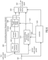
- the full-band analyzer 604 determines which frequency lines or spectral values in the time frequency converter spectrum are to be encoded spectral-line wise and which other spectral portions are to be encoded in a parametric way and these latter spectral values are then reconstructed on the decoder-side with the gap filling procedure.
- the actual encoding operation is performed by a spectral encoder 606 for encoding the first spectral regions or spectral portions with the first resolution and for parametrically encoding the second spectral regions or portions with the second spectral resolution.
- This deactivation can be a deactivation or, as illustrated with respect to, for example, Fig. 7a , is only a kind of "initialization" mode where the other encoding processor is only active to receive and process initialization data in order to initialize internal memories but any specific encoding operation is not performed at all.
- This activation can be done by a certain switch at the input which is not illustrated in Fig. 6 or, preferably, by control lines 621 and 622.
- the second encoding processor 610 does not output anything when the controller 620 has determined that the current audio signal portion should be encoded by the first encoding processor but the second encoding processor is nevertheless provided with initialization data to be active for an instant switching in the future.
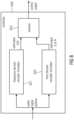
- the second encoding processor comprises a downsampler 900 or sampling rate converter for converting the audio signal portion into a representation with a lower sampling rate, wherein the lower sampling rate is lower than a sampling rate at the input into the first encoding processor.
- a downsampler 900 or sampling rate converter for converting the audio signal portion into a representation with a lower sampling rate, wherein the lower sampling rate is lower than a sampling rate at the input into the first encoding processor.
- the lower sampling rate representation at the output of block 900 only has the low band of the input audio signal portion and this low band is then encoded by a time domain low band encoder 910 which is configured for time-domain encoding the lower sampling rate representation provided by block 900.
- the preprocessor additionally comprises an entropy coder for generating an encoded version of the quantized prediction coefficients.
- the encoded signal former 630 or the specific implementation, i.e., the bit stream multiplexor 613 makes sure that the encoded version of the quantized prediction coefficients is included into the encoded audio signal 632.
- the LPC coefficients are not directly quantized but are converted into an ISF, for example, or any other representation better suited for quantization. This conversion is preferably performed either by the determine LPC coefficients block 1002 or is performed within the block 1010 for quantizing the LPC coefficients.
- a pre-emphasis in the pre-emphasis block 1005 in Fig. 14a .
- the pre-emphasis processing is well-known in the art of time domain encoding and is described in literature referring to the AMR-WB+ processing and the pre-emphasis is particularly configured for compensating for a spectral tilt and, therefore, allows a better calculation of LPC parameters at a given LPC order.
- the controller receives, at an input, the audio signal portion under consideration.
- the controller receives any signal available in the preprocessor 1000 which can either be the original input signal at the input sampling rate or a resampled version at the lower time domain encoder sampling rate or a signal obtained subsequent to the pre-emphasis processing in block 1005.
- the controller 620 addresses a frequency domain encoder simulator 621 and a time domain encoder simulator 622 in order to calculate for each encoder possibility an estimated signal to noise ratio. Subsequently, the selector 623 selects the encoder which has provided the better signal to noise ratio, naturally under the consideration of a predefined bit rate. The selector then identifies the corresponding encoder via the control output.
- the time domain encoder is set into an initialization state or in other embodiments not requiring a very instant switching in a completely deactivated state. However, when it is determined that the audio signal portion under consideration is to be encoded by the time domain encoder, the frequency domain encoder is then deactivated.
- the ACELP encoder/decoder simulation is performed using only a simulation of the adaptive codebook and innovative codebook.
- the ACELP SNR is simply estimated by computing the distortion introduced by a LTP filter in the weighted signal domain (adaptive codebook) and scaling this distortion by a constant factor (innovative codebook).
- the complexity is greatly reduced compared to an approach where TCX and ACELP encoding is executed in parallel.
- the branch with the higher SNR is chosen for the subsequent complete encoding run.
- TCX decoder is run in each frame which outputs a signal at the ACELP sampling rate. This is used to update the memories used for the ACELT encoding path (LPC residual, Mem w0, Memory deemphasis), to enable instant switching from TCX to ACELP. The memory update is performed in each TCX path.
- both encoder simulators 621, 622 implement the actual encoding operations and the results are compared by the selector 623.
- a complete feed forward calculation can be done by performing a signal analysis. For example, when it is determined that the signal is a speech signal by a signal classifier the time domain encoder is selected and when it is determined that the signal is a music signal then the frequency domain encoder is selected. Other procedures in order to distinguish between both encoders based on a signal analysis of the audio signal portion under consideration can also be applied.
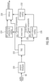
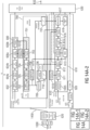
- the audio encoder additionally comprises a cross-processor 700 illustrated in Fig. 7a .
- the cross-processor 700 provides initialization data to the time domain encoder 610 so that the time domain encoder is ready for a seamless switch in a future signal portion.
- the cross-processor 700 provides initialization data to the time domain encoder 610 so that the time domain encoder is ready for a seamless switch in a future signal portion.
- the cross-processor provides a signal derived from the frequency domain encoder 600 to the time domain encoder 610 for the purpose of initializing memories in the time domain encoder since the time domain encoder 610 has a dependency of a current frame from the input or encoded signal of an immediately in time preceding frame.
- the time domain encoder 610 is configured to be initialized by the initialization data in order to encode an audio signal portion following an earlier audio signal portion encoded by the frequency domain encoder 600 in an efficient manner.
- the cross-processor comprises a time converter for converting a frequency domain representation into a time domain representation which can be forwarded to the time domain encoder directly or after some further processing.
- This converter is illustrated in Fig. 14a as an IMDCT (inverse modified discrete cosine transform) block.
- This block 702 has a different transform size compared to the time-frequency converter block 602 indicated in Fig. 14a block (modified discrete cosine transform block).
- the time-frequency converter 602 operates at the input sampling rate and the inverse modified discrete cosine transform 702 operates at the lower ACELP sampling rate.
- the residual signal generated by block 611 is provided to an adaptive codebook 612 and, furthermore, the adaptive codebook 612 is connected to an innovative codebook stage 614 and the codebook data from the adaptive codebook 612 and from the innovative codebook are input into the bitstream multiplexor as illustrated.
- a preferred embodiment of an audio encoder therefore comprises the following parts:
- the preferred audio decoder is described in the following:
- the waveform decoder part consists of a full-band TCX decoder path with IGF both operating at the input sampling rate of the codec.
- an alternative ACELP decoder path at lower sampling rate exists that is reinforced further downstream by a TD-BWE.
- the full-band frequency domain decoder 1120 comprises a first decoding block 1122a for decoding the high resolution spectral coefficients and for additionally performing noise filling in the low band portion as known, for example, from the USAC technology. Furthermore, the full-band decoder comprises an IGF processor 1122b for filling the spectral holes using synthesized spectral values which have been only parametrically and, therefore, encoded with a low resolution on the encoder-side.
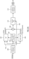
- the output of the LPC synthesis filter 1143 is input into a de-emphasis stage 1144 for canceling or undoing the processing introduced by the pre-emphasis stage 1005 of the pre-processor 1000 of Fig. 14a .
- the result is the time domain output signal at a low sampling rate and a low band and in case the frequency domain output is required, the switch 1480 is in the indicated position and the output of the de-emphasis stage 1144 is introduced into the upsampler 1210 and then mixed with the high bands from the time domain bandwidth extension decoder 1220.
- the cross-processor 1170 further comprises, alone or in addition to other elements, a delay stage 1172 for delaying the further decoded first signal portion and for feeding the delayed decoded first signal portion into a de-emphasis stage 1144 of the second decoding processor for initialization.
- the cross-processor comprises, in addition or alternatively, a pre-emphasis filter 1173 and a delay stage 1175 for filtering and delaying a further decoded first signal portion and for providing the delayed output of block 1175 into an LPC synthesis filtering stage 1143 of the ACELP decoder for the purpose of initialization.
- a further specific feature is a cross signal path for the ACELP initialization to enable seamless switching.
- a further aspect is that a short IMDCT is fed with a lower part of high-rate long MDCT coefficients to efficiently implement a sample rate conversion in the cross-path.
- An additional feature is a cross-signal path to the QMF allowing compensating the delay gap between ACELP resampled output and a filterbank-TCX/IGF output when switching from ACELP to TCX.
- Fig. 14c is discussed as a preferred implementation of a time domain decoder operating either as a stand-alone decoder or in the combination with the full-band capable frequency domain decoder.
- the time domain decoder comprises an ACELP decoder, a subsequently connected resampler or upsampler and a time domain bandwidth extension functionality.
- the ACELP decoder comprises an ACELP decoding stage for restoring gains and the innovative codebook 1149, an ACELP-adaptive codebook stage 1141, an ACELP post-processor 1142, an LPC synthesis filter 1143 controlled by quantized LPC coefficients from a bitstream demultiplexer or encoded signal parser and the subsequently connected de-emphasis stage 1144.
- the time domain residual signal being at an ACELP sampling rate is input into a time domain bandwidth extension decoder 1220 which provides a high band at the outputs.
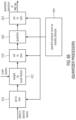
- Fig. 1a illustrates an apparatus for encoding an audio signal 99.
- the audio signal 99 is input into a time spectrum converter 100 for converting an audio signal having a sampling rate into a spectral representation 101 output by the time spectrum converter.
- the spectrum 101 is input into a spectral analyzer 102 for analyzing the spectral representation 101.
- the spectral analyzer 101 is configured for determining a first set of first spectral portions 103 to be encoded with a first spectral resolution and a different second set of second spectral portions 105 to be encoded with a second spectral resolution.
- the second spectral resolution is smaller than the first spectral resolution.
- the second set of second spectral portions 105 is input into a parameter calculator or parametric coder 104 for calculating spectral envelope information having the second spectral resolution. Furthermore, a spectral domain audio coder 106 is provided for generating a first encoded representation 107 of the first set of first spectral portions having the first spectral resolution. Furthermore, the parameter calculator/parametric coder 104 is configured for generating a second encoded representation 109 of the second set of second spectral portions. The first encoded representation 107 and the second encoded representation 109 are input into a bit stream multiplexer or bit stream former 108 and block 108 finally outputs the encoded audio signal for transmission or storage on a storage device.
- Fig. 1b illustrates a decoder matching with the encoder of Fig. 1a .
- the first encoded representation 107 is input into a spectral domain audio decoder 112 for generating a first decoded representation of a first set of first spectral portions, the decoded representation having a first spectral resolution.
- the second encoded representation 109 is input into a parametric decoder 114 for generating a second decoded representation of a second set of second spectral portions having a second spectral resolution being lower than the first spectral resolution.
- the decoder further comprises a frequency regenerator 116 for regenerating a reconstructed second spectral portion having the first spectral resolution using a first spectral portion.
- the frequency regenerator 116 performs a tile filling operation, i.e., uses a tile or portion of the first set of first spectral portions and copies this first set of first spectral portions into the reconstruction range or reconstruction band having the second spectral portion and typically performs spectral envelope shaping or another operation as indicated by the decoded second representation output by the parametric decoder 114, i.e., by using the information on the second set of second spectral portions.
- Fig. 2b illustrates an implementation of the Fig. 1a encoder.
- An audio input signal 99 is input into an analysis filterbank 220 corresponding to the time spectrum converter 100 of Fig. 1a .
- a temporal noise shaping operation is performed in TNS block 222. Therefore, the input into the spectral analyzer 102 of Fig. 1a corresponding to a block tonal mask 226 of Fig. 2b can either be full spectral values, when the temporal noise shaping/ temporal tile shaping operation is not applied or can be spectral residual values, when the TNS operation as illustrated in Fig. 2b , block 222 is applied.
- a joint channel coding 228 can additionally be performed, so that the spectral domain encoder 106 of Fig. 1a may comprise the joint channel coding block 228. Furthermore, an entropy coder 232 for performing a lossless data compression is provided which is also a portion of the spectral domain encoder 106 of Fig. 1a .
- the spectral analyzer/tonal mask 226 separates the output of TNS block 222 into the core band and the tonal components corresponding to the first set of first spectral portions 103 and the residual components corresponding to the second set of second spectral portions 105 of Fig. 1a .
- the block 224 indicated as IGF parameter extraction encoding corresponds to the parametric coder 104 of Fig. 1a and the bitstream multiplexer 230 corresponds to the bitstream multiplexer 108 of Fig. 1a .
- the spectral analyzer 226 preferably applies a tonality mask.
- This tonality mask estimation stage is used to separate tonal components from the noise-like components in the signal. This allows the core coder 228 to code all tonal components with a psycho-acoustic module.
- the tonality mask estimation stage can be implemented in numerous different ways and is preferably implemented similar in its functionality to the sinusoidal track estimation stage used in sine and noise-modeling for speech/audio coding [8, 9] or an HILN model based audio coder described in [10].
- an implementation is used which is easy to implement without the need to maintain birth-death trajectories, but any other tonality or noise detector can be used as well.
- the IGF module calculates the similarity that exists between a source region and a target region.
- the target region will be represented by the spectrum from the source region.
- the measure of similarity between the source and target regions is done using a cross-correlation approach.
- the target region is split into nTar non-overlapping frequency tiles. For every tile in the target region, nSrc source tiles are created from a fixed start frequency. These source tiles overlap by a factor between 0 and 1, where 0 means 0% overlap and 1 means 100% overlap. Each of these source tiles is correlated with the target tile at various lags to find the source tile that best matches the target tile.
- the best matching tile number is stored in tileNum [ idx_tar ]
- the lag at which it best correlates with the target is stored in xcorr _ lag [ idx _ tar ][ idx _ src ]
- the sign of the correlation is stored in xcorr_sign [ idx_tar ][ idx_src ] .
- the source tile needs to be multiplied by -1 before the tile filling process at the decoder.
- the IGF module also takes care of not overwriting the tonal components in the spectrum since the tonal components are preserved using the tonality mask.
- a band-wise energy parameter is used to store the energy of the target region enabling us to reconstruct the spectrum accurately.
- This method has certain advantages over the classical SBR [1] in that the harmonic grid of a multi-tone signal is preserved by the core coder while only the gaps between the sinusoids is filled with the best matching "shaped noise" from the source region.
- Another advantage of this system compared to ASR (Accurate Spectral Replacement) [2-4] is the absence of a signal synthesis stage which creates the important portions of the signal at the decoder. Instead, this task is taken over by the core coder, enabling the preservation of important components of the spectrum.
- Another advantage of the proposed system is the continuous scalability that the features offer.
- tile choice stabilization technique which removes frequency domain artifacts such as trilling and musical noise.
- the encoder analyses each destination region energy band, typically performing a cross-correlation of the spectral values and if a certain threshold is exceeded, sets a joint flag for this energy band.
- the left and right channel energy bands are treated individually if this joint stereo flag is not set.
- the joint stereo flag is set, both the energies and the patching are performed in the joint stereo domain.
- the joint stereo information for the IGF regions is signaled similar the joint stereo information for the core coding, including a flag indicating in case of prediction if the direction of the prediction is from downmix to residual or vice versa.
- the energies can be calculated from the transmitted energies in the L/R-domain.
- midNrg k leftNrg k + rightNrg k ;
- sideNrg k leftNrg k ⁇ rightNrg k ; with k being the frequency index in the transform domain.
- Another solution is to calculate and transmit the energies directly in the joint stereo domain for bands where joint stereo is active, so no additional energy transformation is needed at the decoder side.
- This processing ensures that from the tiles used for regenerating highly correlated destination regions and panned destination regions, the resulting left and right channels still represent a correlated and panned sound source even if the source regions are not correlated, preserving the stereo image for such regions.
- joint stereo flags are transmitted that indicate whether L/R or M/S as an example for the general joint stereo coding shall be used.
- the core signal is decoded as indicated by the joint stereo flags for the core bands.
- the core signal is stored in both L/R and M/S representation.
- the source tile representation is chosen to fit the target tile representation as indicated by the joint stereo information for the IGF bands.
- TNS Temporal Noise Shaping
- IGF is based on an MDCT representation. For efficient coding, preferably long blocks of approx. 20 ms have to be used. If the signal within such a long block contains transients, audible pre- and post-echoes occur in the IGF spectral bands due to the tile filling.
- Fig. 7c shows a typical pre-echo effect before the transient onset due to IGF. On the left side, the spectrogram of the original signal is shown and on the right side the spectrogram of the bandwidth extended signal without TNS filtering is shown.
- TNS temporal tile shaping
- the required TTS prediction coefficients are calculated and applied using the full spectrum on encoder side as usual.
- the TNS/TTS start and stop frequencies are not affected by the IGF start frequency f IGFstart of the IGF tool.
- the TTS stop frequency is increased to the stop frequency of the IGF tool, which is higher than f IGFstart .
- the TNS/TTS coefficients are applied on the full spectrum again, i.e.
- TTS the core spectrum plus the regenerated spectrum plus the tonal components from the tonality map (see Fig. 7e).
- the application of TTS is necessary to form the temporal envelope of the regenerated spectrum to match the envelope of the original signal again. So the shown pre-echoes are reduced. In addition, it still shapes the quantization noise in the signal below f IGFstart as usual with TNS.
- spectral patching on an audio signal corrupts spectral correlation at the patch borders and thereby impairs the temporal envelope of the audio signal by introducing dispersion.
- another benefit of performing the IGF tile filling on the residual signal is that, after application of the shaping filter, tile borders are seamlessly correlated, resulting in a more faithful temporal reproduction of the signal.
- Fig. 2a illustrates the corresponding decoder implementation.
- the bitstream in Fig. 2a corresponding to the encoded audio signal is input into the demultiplexer/decoder which would be connected, with respect to Fig. 1b , to the blocks 112 and 114.
- the bitstream demultiplexer separates the input audio signal into the first encoded representation 107 of Fig. 1b and the second encoded representation 109 of Fig. 1b .
- the first encoded representation having the first set of first spectral portions is input into the joint channel decoding block 204 corresponding to the spectral domain decoder 112 of Fig. 1b .
- the second encoded representation is input into the parametric decoder 114 not illustrated in Fig.
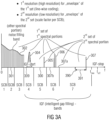
- Fig. 3a illustrates a schematic representation of the spectrum.
- the spectrum is subdivided in scale factor bands SCB where there are seven scale factor bands SCB1 to SCB7 in the illustrated example of Fig. 3a .
- the scale factor bands can be AAC scale factor bands which are defined in the AAC standard and have an increasing bandwidth to upper frequencies as illustrated in Fig. 3a schematically. It is preferred to perform intelligent gap filling not from the very beginning of the spectrum, i.e., at low frequencies, but to start the IGF operation at an IGF start frequency illustrated at 309. Therefore, the core frequency band extends from the lowest frequency to the IGF start frequency.
- Fig. 3a illustrates a spectrum which is exemplarily input into the spectral domain encoder 106 or the joint channel coder 228, i.e., the core encoder operates in the full range, but encodes a significant amount of zero spectral values, i.e., these zero spectral values are quantized to zero or are set to zero before quantizing or subsequent to quantizing.
- the core encoder operates in full range, i.e., as if the spectrum would be as illustrated, i.e., the core decoder does not necessarily have to be aware of any intelligent gap filling or encoding of the second set of second spectral portions with a lower spectral resolution.
- the high resolution is defined by a line-wise coding of spectral lines such as MDCT lines
- the second resolution or low resolution is defined by, for example, calculating only a single spectral value per scale factor band, where a scale factor band covers several frequency lines.
- the second low resolution is, with respect to its spectral resolution, much lower than the first or high resolution defined by the line-wise coding typically applied by the core encoder such as an AAC or USAC core encoder.
- an additional noise-filling operation in the core band i.e., lower in frequency than the IGF start frequency, i.e., in scale factor bands SCB1 to SCB3 can be applied in addition.
- noise-filling there exist several adjacent spectral lines which have been quantized to zero. On the decoder-side, these quantized to zero spectral values are re-synthesized and the re-synthesized spectral values are adjusted in their magnitude using a noise-filling energy such as NF 2 illustrated at 308 in Fig. 3b .
- noise-filling energy which can be given in absolute terms or in relative terms particularly with respect to the scale factor as in USAC corresponds to the energy of the set of spectral values quantized to zero.
- noise-filling spectral lines can also be considered to be a third set of third spectral portions which are regenerated by straightforward noise-filling synthesis without any IGF operation relying on frequency regeneration using frequency tiles from other frequencies for reconstructing frequency tiles using spectral values from a source range and the energy information E 1 , E 2 , E 3 , E 4 .
- the bands, for which energy information is calculated coincide with the scale factor bands.
- an energy information value grouping is applied so that, for example, for scale factor bands 4 and 5, only a single energy information value is transmitted, but even in this embodiment, the borders of the grouped reconstruction bands coincide with borders of the scale factor bands. If different band separations are applied, then certain re-calculations or synchronization calculations may be applied, and this can make sense depending on the certain implementation.
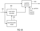
- the spectral domain encoder 106 of Fig. 1a is a psycho-acoustically driven encoder as illustrated in Fig. 4a .
- the to be encoded audio signal after having been transformed into the spectral range (401 in Fig. 4a ) is forwarded to a scale factor calculator 400.
- the scale factor calculator is controlled by a psycho-acoustic model additionally receiving the to be quantized audio signal or receiving, as in the MPEG1/2 Layer 3 or MPEG AAC standard, a complex spectral representation of the audio signal.
- the psycho-acoustic model calculates, for each scale factor band, a scale factor representing the psycho-acoustic threshold.
- the scale factors are then, by cooperation of the well-known inner and outer iteration loops or by any other suitable encoding procedure adjusted so that certain bitrate conditions are fulfilled. Then, the to be quantized spectral values on the one hand and the calculated scale factors on the other hand are input into a quantizer processor 404. In the straightforward audio encoder operation, the to be quantized spectral values are weighted by the scale factors and, the weighted spectral values are then input into a fixed quantizer typically having a compression functionality to upper amplitude ranges.
- quantization indices which are then forwarded into an entropy encoder typically having specific and very efficient coding for a set of zero-quantization indices for adjacent frequency values or, as also called in the art, a "run" of zero values.
- the quantizer processor typically receives information on the second spectral portions from the spectral analyzer.
- the quantizer processor 404 makes sure that, in the output of the quantizer processor 404, the second spectral portions as identified by the spectral analyzer 102 are zero or have a representation acknowledged by an encoder or a decoder as a zero representation which can be very efficiently coded, specifically when there exist "runs" of zero values in the spectrum.
- Fig. 4b illustrates an implementation of the quantizer processor.
- the MDCT spectral values can be input into a set to zero block 410. Then, the second spectral portions are already set to zero before a weighting by the scale factors in block 412 is performed.
- block 410 is not provided, but the set to zero cooperation is performed in block 418 subsequent to the weighting block 412.
- the set to zero operation can also be performed in a set to zero block 422 subsequent to a quantization in the quantizer block 420.
- blocks 410 and 418 would not be present. Generally, at least one of the blocks 410, 418, 422 are provided depending on the specific implementation.
- a quantized spectrum is obtained corresponding to what is illustrated in Fig. 3a .
- This quantized spectrum is then input into an entropy coder such as 232 in Fig. 2b which can be a Huffman coder or an arithmetic coder as, for example, defined in the USAC standard.
- the set to zero blocks 410, 418, 422, which are provided alternatively to each other or in parallel are controlled by the spectral analyzer 424.
- the spectral analyzer preferably comprises any implementation of a well-known tonality detector or comprises any different kind of detector operative for separating a spectrum into components to be encoded with a high resolution and components to be encoded with a low resolution.
- Other such algorithms implemented in the spectral analyzer can be a voice activity detector, a noise detector, a speech detector or any other detector deciding, depending on spectral information or associated metadata on the resolution requirements for different spectral portions.
- 3b for a scale factor band 6 is also input into block 510.
- the reconstructed second spectral portion in the reconstruction band has already been generated by frequency tile filling using a source range and the reconstruction band then corresponds to the target range.
- an energy adjustment of the frame is performed to then finally obtain the complete reconstructed frame having the N values as, for example, obtained at the output of combiner 208 of Fig. 2a .
- an inverse block transform/interpolation is performed to obtain 248 time domain values for the for example 124 spectral values at the input of block 512.
- a synthesis windowing operation is performed in block 514 which is again controlled by a long window/short window indication transmitted as side information in the encoded audio signal.
- an overlap/add operation with a previous time frame is performed.
- MDCT applies a 50% overlap so that, for each new time frame of 2N values, N time domain values are finally output.
- a 50% overlap is heavily preferred due to the fact that it provides critical sampling and a continuous crossover from one frame to the next frame due to the overlap/add operation in block 516.
- a noise-filling operation can additionally be applied not only below the IGF start frequency, but also above the IGF start frequency such as for the contemplated reconstruction band coinciding with scale factor band 6 of Fig. 3a .
- noise-filling spectral values can also be input into the frame builder/adjuster 510 and the adjustment of the noise-filling spectral values can also be applied within this block or the noise-filling spectral values can already be adjusted using the noise-filling energy before being input into the frame builder/adjuster 510.
- an IGF operation i.e., a frequency tile filling operation using spectral values from other portions can be applied in the complete spectrum.
- a spectral tile filling operation can not only be applied in the high band above an IGF start frequency but can also be applied in the low band.
- the noise-filling without frequency tile filling can also be applied not only below the IGF start frequency but also above the IGF start frequency. It has, however, been found that high quality and high efficient audio encoding can be obtained when the noise-filling operation is limited to the frequency range below the IGF start frequency and when the frequency tile filling operation is restricted to the frequency range above the IGF start frequency as illustrated in Fig. 3a .
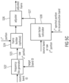
- Block 522 is a frequency tile generator receiving, not only a target band ID, but additionally receiving a source band ID.
- a source band ID Exemplarily, it has been determined on the encoder-side that the scale factor band 3 of Fig. 3a is very well suited for reconstructing scale factor band 7. Thus, the source band ID would be 2 and the target band ID would be 7.
- the frequency tile generator 522 applies a copy up or harmonic tile filling operation or any other tile filling operation to generate the raw second portion of spectral components 523.
- the raw second portion of spectral components has a frequency resolution identical to the frequency resolution included in the first set of first spectral portions.
- the first spectral portion of the reconstruction band such as 307 of Fig. 3a is input into a frame builder 524 and the raw second portion 523 is also input into the frame builder 524.
- the reconstructed frame is adjusted by the adjuster 526 using a gain factor for the reconstruction band calculated by the gain factor calculator 528.
- the first spectral portion in the frame is not influenced by the adjuster 526, but only the raw second portion for the reconstruction frame is influenced by the adjuster 526.
- the gain factor calculator 528 analyzes the source band or the raw second portion 523 and additionally analyzes the first spectral portion in the reconstruction band to finally find the correct gain factor 527 so that the energy of the adjusted frame output by the adjuster 526 has the energy E 4 when a scale factor band 7 is contemplated.
- the spectral analyzer is also implemented to calculating similarities between first spectral portions and second spectral portions and to determine, based on the calculated similarities, for a second spectral portion in a reconstruction range a first spectral portion matching with the second spectral portion as far as possible. Then, in this variable source range/destination range implementation, the parametric coder will additionally introduce into the second encoded representation a matching information indicating for each destination range a matching source range. On the decoder-side, this information would then be used by a frequency tile generator 522 of Fig. 5c illustrating a generation of a raw second portion 523 based on a source band ID and a target band ID.
- the encoder operates without downsampling and the decoder operates without upsampling.
- the spectral domain audio coder is configured to generate a spectral representation having a Nyquist frequency defined by the sampling rate of the originally input audio signal.
- the spectral analyzer is configured to analyze the spectral representation starting with a gap filling start frequency and ending with a maximum frequency represented by a maximum frequency included in the spectral representation, wherein a spectral portion extending from a minimum frequency up to the gap filling start frequency belongs to the first set of spectral portions and wherein a further spectral portion such as 304, 305, 306, 307 having frequency values above the gap filling frequency additionally is included in the first set of first spectral portions.
- the spectral domain audio decoder 112 is configured so that a maximum frequency represented by a spectral value in the first decoded representation is equal to a maximum frequency included in the time representation having the sampling rate wherein the spectral value for the maximum frequency in the first set of first spectral portions is zero or different from zero.
- a scale factor for the scale factor band exists, which is generated and transmitted irrespective of whether all spectral values in this scale factor band are set to zero or not as discussed in the context of Figs. 3a and 3b .
- the invention is, therefore, advantageous that with respect to other parametric techniques to increase compression efficiency, e.g. noise substitution and noise filling (these techniques are exclusively for efficient representation of noise like local signal content) the invention allows an accurate frequency reproduction of tonal components.
- noise substitution and noise filling these techniques are exclusively for efficient representation of noise like local signal content
- the invention allows an accurate frequency reproduction of tonal components.
- no state-of-the-art technique addresses the efficient parametric representation of arbitrary signal content by spectral gap filling without the restriction of a fixed a-priory division in low band (LF) and high band (HF).
- Embodiments of the inventive system improve the state-of-the-art approaches and thereby provides high compression efficiency, no or only a small perceptual annoyance and full audio bandwidth even for low bitrates.
- the general system consists of
- a first step towards a more efficient system is to remove the need for transforming spectral data into a second transform domain different from the one of the core coder.
- AAC audio codecs
- AAC audio codecs
- a second requirement for the BWE system would be the need to preserve the tonal grid whereby even HF tonal components are preserved and the quality of the coded audio is thus superior to the existing systems.
- IGF Intelligent Gap Filling
- the spectral domain decoder 112 corresponding to block 1122a is configured to output a sequence of decoded frames of spectral values, a decoded frame being the first decoded representation, wherein the frame comprises spectral values for the first set of spectral portions and zero indications for the second spectral portions.
- the apparatus for decoding furthermore comprises a combiner 208.
- the spectral values are generated by a frequency regenerator for the second set of second spectral portions, where both, the combiner and the frequency regenerator are included within block 1122b.
- a reconstructed spectral frame comprising spectral values for the first set of the first spectral portions and the second set of spectral portions are obtained and the spectrum-time converter 118 corresponding to the IMDCT block 1124 in Fig. 14b then converts the reconstructed spectral frame into the time representation.
- the spectrum-time converter 118 or 1124 is configured to perform an inverse modified discrete cosine transform 512, 514 and further comprises an overlap-add stage 516 for overlapping and adding subsequent time domain frames
- the spectral domain audio decoder 1122a is configured to generate the first decoded representation so that the first decoded representation has a Nyquist frequency defining a sampling rate being equal to a sampling rate of the time representation generated by the spectrum-time converter 1124.
- the decoder 1112 or 1122a is configured to generate the first decoded representation so that a first spectral portion 306 is placed with respect to frequency between two second spectral portions 307a, 307b.
- a maximum frequency represented by a spectral value for the maximum frequency in the first decoded representation is equal to a maximum frequency included in the time representation generated by the spectrum-time converter, wherein the spectral value for the maximum frequency in the first representation is zero or different from zero.
- the encoded first audio signal portion further comprises an encoded representation of a third set of third spectral portions to be reconstructed by noise filling
- the first decoding processor 1120 additionally includes a noise filler included in block 1122b for extracting noise filling information 308 from an encoded representation of the third set of third spectral portions and for applying a noise filling operation in the third set of third spectral portions without using a first spectral portion in a different frequency range.
- the spectral analyzer or full-band analyzer 604 is configured to analyze the representation generated by the time-frequency converter 602 for determining a first set of first spectral portions to be encoded with the first high spectral resolution and the different second set of second spectral portions to be encoded with a second spectral resolution which is lower than the first spectral resolution and, by means of the spectral analyzer, a first spectral portion 306 is determined, with respect to frequency, between two second spectral portions in Fig. 3 at 307a and 307b.
- the spectral analyzer is configured for analyzing the spectral representation up to a maximum analysis frequency being at least one quarter of a sampling frequency of the audio signal.
- the spectral domain audio encoder is configured to generate a spectral representation having a Nyquist frequency defined by the sampling rate of the audio input signal or the first portion of the audio signal processed by the first encoding processor operating in the frequency domain.
- the spectral domain audio encoder 606 is furthermore configured to provide the first encoded representation so that, for a frame of a sampled audio signal, the encoded representation comprises the first set of first spectral portions and the second set of second spectral portions, wherein the spectral values in the second set of spectral portions are encoded as zero or noise values.
- the full band analyzer 604 or 102 is configured to analyze the spectral representation starting with the gap-filing start frequency 209 and ending with a maximum frequency f max represented by a maximum frequency included in the spectral representation and a spectral portion extending from a minimum frequency up to the gap-filling start frequency 309 belongs to the first set of first spectral portions.
- embodiments of the invention can be implemented in hardware or in software.
- the implementation can be performed using a digital storage medium, for example a floppy disc, a DVD, a Blu-Ray, a CD, a ROM, a PROM, and EPROM, an EEPROM or a FLASH memory, having electronically readable control signals stored thereon, which cooperate (or are capable of cooperating) with a programmable computer system such that the respective method is performed. Therefore, the digital storage medium may be computer readable.
- a further embodiment of the invention method is, therefore, a data stream or a sequence of signals representing the computer program for performing one of the inventive methods described herein.
- the data stream or the sequence of signals may, for example, be configured to be transferred via a data communication connection, for example, via the internet.
- a further embodiment according to the invention comprises an apparatus or a system configured to transfer (for example, electronically or optically) a computer program for performing one of the inventive methods described herein to a receiver.
- the receiver may, for example, be a computer, a mobile device, a memory device or the like.
- the apparatus or system may, for example, comprise a file server for transferring the computer program to the receiver .
Landscapes
- Engineering & Computer Science (AREA)
- Physics & Mathematics (AREA)
- Computational Linguistics (AREA)
- Signal Processing (AREA)
- Health & Medical Sciences (AREA)
- Audiology, Speech & Language Pathology (AREA)
- Human Computer Interaction (AREA)
- Acoustics & Sound (AREA)
- Multimedia (AREA)
- Spectroscopy & Molecular Physics (AREA)
- Quality & Reliability (AREA)
- Compression, Expansion, Code Conversion, And Decoders (AREA)
Applications Claiming Priority (5)
| Application Number | Priority Date | Filing Date | Title |
|---|---|---|---|
| EP14178817.4A EP2980794A1 (de) | 2014-07-28 | 2014-07-28 | Audiocodierer und -decodierer mit einem Frequenzdomänenprozessor und Zeitdomänenprozessor |
| EP15739300.0A EP3186809B1 (de) | 2014-07-28 | 2015-07-24 | Audiokodierung und -dekodierung in den frequenz- und zeitdomänen |
| PCT/EP2015/067003 WO2016016123A1 (en) | 2014-07-28 | 2015-07-24 | Audio encoder and decoder using a frequency domain processor with full-band gap filling and a time domain processor |
| EP19160134.3A EP3511936B1 (de) | 2014-07-28 | 2015-07-24 | Audiokodierung mit einem frequenzbereichsprozessor und einem zeitbereichsprozessor |
| EP23184408.5A EP4239634B1 (de) | 2014-07-28 | 2015-07-24 | Audiocodierung mit einem frequenzbereichsprozessor und einem zeitbereichsprozessor |
Related Parent Applications (3)
| Application Number | Title | Priority Date | Filing Date |
|---|---|---|---|
| EP23184408.5A Division EP4239634B1 (de) | 2014-07-28 | 2015-07-24 | Audiocodierung mit einem frequenzbereichsprozessor und einem zeitbereichsprozessor |
| EP19160134.3A Division EP3511936B1 (de) | 2014-07-28 | 2015-07-24 | Audiokodierung mit einem frequenzbereichsprozessor und einem zeitbereichsprozessor |
| EP15739300.0A Division EP3186809B1 (de) | 2014-07-28 | 2015-07-24 | Audiokodierung und -dekodierung in den frequenz- und zeitdomänen |
Publications (1)
| Publication Number | Publication Date |
|---|---|
| EP4576076A1 true EP4576076A1 (de) | 2025-06-25 |
Family
ID=51224876
Family Applications (5)
| Application Number | Title | Priority Date | Filing Date |
|---|---|---|---|
| EP14178817.4A Withdrawn EP2980794A1 (de) | 2014-07-28 | 2014-07-28 | Audiocodierer und -decodierer mit einem Frequenzdomänenprozessor und Zeitdomänenprozessor |
| EP25174210.2A Pending EP4576076A1 (de) | 2014-07-28 | 2015-07-24 | Audiokodierung mit einem frequenzbereichsprozessor und einem zeitbereichprozessor |
| EP23184408.5A Active EP4239634B1 (de) | 2014-07-28 | 2015-07-24 | Audiocodierung mit einem frequenzbereichsprozessor und einem zeitbereichsprozessor |
| EP15739300.0A Active EP3186809B1 (de) | 2014-07-28 | 2015-07-24 | Audiokodierung und -dekodierung in den frequenz- und zeitdomänen |
| EP19160134.3A Active EP3511936B1 (de) | 2014-07-28 | 2015-07-24 | Audiokodierung mit einem frequenzbereichsprozessor und einem zeitbereichsprozessor |
Family Applications Before (1)
| Application Number | Title | Priority Date | Filing Date |
|---|---|---|---|
| EP14178817.4A Withdrawn EP2980794A1 (de) | 2014-07-28 | 2014-07-28 | Audiocodierer und -decodierer mit einem Frequenzdomänenprozessor und Zeitdomänenprozessor |
Family Applications After (3)
| Application Number | Title | Priority Date | Filing Date |
|---|---|---|---|
| EP23184408.5A Active EP4239634B1 (de) | 2014-07-28 | 2015-07-24 | Audiocodierung mit einem frequenzbereichsprozessor und einem zeitbereichsprozessor |
| EP15739300.0A Active EP3186809B1 (de) | 2014-07-28 | 2015-07-24 | Audiokodierung und -dekodierung in den frequenz- und zeitdomänen |
| EP19160134.3A Active EP3511936B1 (de) | 2014-07-28 | 2015-07-24 | Audiokodierung mit einem frequenzbereichsprozessor und einem zeitbereichsprozessor |
Country Status (19)
| Country | Link |
|---|---|
| US (5) | US10332535B2 (de) |
| EP (5) | EP2980794A1 (de) |
| JP (5) | JP6549217B2 (de) |
| KR (1) | KR102009210B1 (de) |
| CN (6) | CN113948100B (de) |
| AR (1) | AR101344A1 (de) |
| AU (1) | AU2015295605B2 (de) |
| BR (4) | BR122022012517B1 (de) |
| CA (1) | CA2955095C (de) |
| ES (3) | ES2972128T3 (de) |
| MX (1) | MX362424B (de) |
| MY (1) | MY187280A (de) |
| PL (3) | PL3186809T3 (de) |
| PT (1) | PT3186809T (de) |
| RU (1) | RU2671997C2 (de) |
| SG (1) | SG11201700685XA (de) |
| TR (1) | TR201908602T4 (de) |
| TW (1) | TWI570710B (de) |
| WO (1) | WO2016016123A1 (de) |
Families Citing this family (38)
| Publication number | Priority date | Publication date | Assignee | Title |
|---|---|---|---|---|
| EP2144230A1 (de) * | 2008-07-11 | 2010-01-13 | Fraunhofer-Gesellschaft zur Förderung der angewandten Forschung e.V. | Audiokodierungs-/Audiodekodierungsschema geringer Bitrate mit kaskadierten Schaltvorrichtungen |
| EP2980795A1 (de) | 2014-07-28 | 2016-02-03 | Fraunhofer-Gesellschaft zur Förderung der angewandten Forschung e.V. | Audiokodierung und -decodierung mit Nutzung eines Frequenzdomänenprozessors, eines Zeitdomänenprozessors und eines Kreuzprozessors zur Initialisierung des Zeitdomänenprozessors |
| EP2980794A1 (de) | 2014-07-28 | 2016-02-03 | Fraunhofer-Gesellschaft zur Förderung der angewandten Forschung e.V. | Audiocodierer und -decodierer mit einem Frequenzdomänenprozessor und Zeitdomänenprozessor |
| PL4134953T3 (pl) * | 2016-04-12 | 2025-04-14 | Fraunhofer-Gesellschaft zur Förderung der angewandten Forschung e.V. | Koder audio do kodowania sygnału audio, sposób kodowania sygnału audio i program komputerowy, z uwzględnieniem wykrytego szczytowego obszaru widmowego w paśmie wyższej częstotliwości |
| JP6976277B2 (ja) | 2016-06-22 | 2021-12-08 | ドルビー・インターナショナル・アーベー | 第一の周波数領域から第二の周波数領域にデジタル・オーディオ信号を変換するためのオーディオ・デコーダおよび方法 |
| US10249307B2 (en) | 2016-06-27 | 2019-04-02 | Qualcomm Incorporated | Audio decoding using intermediate sampling rate |
| EP3288031A1 (de) | 2016-08-23 | 2018-02-28 | Fraunhofer-Gesellschaft zur Förderung der angewandten Forschung e.V. | Vorrichtung und verfahren zur codierung eines audiosignals mit einem kompensationswert |
| US10354668B2 (en) | 2017-03-22 | 2019-07-16 | Immersion Networks, Inc. | System and method for processing audio data |
| TWI873683B (zh) | 2017-03-23 | 2025-02-21 | 瑞典商都比國際公司 | 用於音訊信號之高頻重建的諧波轉置器的回溯相容整合 |
| EP3382703A1 (de) * | 2017-03-31 | 2018-10-03 | Fraunhofer-Gesellschaft zur Förderung der angewandten Forschung e.V. | Vorrichtung und verfahren zur verarbeitung eines audiosignals |
| CN110998721B (zh) | 2017-07-28 | 2024-04-26 | 弗劳恩霍夫应用研究促进协会 | 用于使用宽频带滤波器生成的填充信号对已编码的多声道信号进行编码或解码的装置 |
| JP7214726B2 (ja) * | 2017-10-27 | 2023-01-30 | フラウンホッファー-ゲゼルシャフト ツァ フェルダールング デァ アンゲヴァンテン フォアシュンク エー.ファオ | ニューラルネットワークプロセッサを用いた帯域幅が拡張されたオーディオ信号を生成するための装置、方法またはコンピュータプログラム |
| TWI869186B (zh) * | 2018-01-26 | 2025-01-01 | 瑞典商都比國際公司 | 用於執行一音訊信號之高頻重建之方法、音訊處理單元及非暫時性電腦可讀媒體 |
| ES3059239T3 (en) | 2018-07-04 | 2026-03-19 | Fraunhofer Ges Forschung | Multisignal encoder, multisignal decoder, and related methods using signal whitening or signal post processing |
| US10911013B2 (en) | 2018-07-05 | 2021-02-02 | Comcast Cable Communications, Llc | Dynamic audio normalization process |
| CN109215670B (zh) * | 2018-09-21 | 2021-01-29 | 西安蜂语信息科技有限公司 | 音频数据的传输方法、装置、计算机设备和存储介质 |
| EP3671741A1 (de) * | 2018-12-21 | 2020-06-24 | FRAUNHOFER-GESELLSCHAFT zur Förderung der angewandten Forschung e.V. | Audioprozessor und verfahren zum erzeugen eines frequenzverbesserten audiosignals mittels impulsverarbeitung |
| EP3981077B1 (de) * | 2019-06-05 | 2025-10-29 | Hitachi Energy Ltd | Verfahren und vorrichtung zur ermöglichung der speicherung von daten aus einem industriellen automatisierungssteuerungssystem oder stromsystem |
| TWI703559B (zh) * | 2019-07-08 | 2020-09-01 | 瑞昱半導體股份有限公司 | 音效編碼解碼電路及音頻資料的處理方法 |
| CN110794273A (zh) * | 2019-11-19 | 2020-02-14 | 哈尔滨理工大学 | 含有高压驱动保护电极的电位时域谱测试系统 |
| CN113192521B (zh) * | 2020-01-13 | 2024-07-05 | 华为技术有限公司 | 一种音频编解码方法和音频编解码设备 |
| CN113470667B (zh) * | 2020-03-11 | 2024-09-27 | 腾讯科技(深圳)有限公司 | 语音信号的编解码方法、装置、电子设备及存储介质 |
| CN113963703B (zh) * | 2020-07-03 | 2025-05-02 | 华为技术有限公司 | 一种音频编码的方法和编解码设备 |
| KR20220005379A (ko) | 2020-07-06 | 2022-01-13 | 한국전자통신연구원 | 천이구간 부호화 왜곡에 강인한 오디오 부호화/복호화 장치 및 방법 |
| CN113948094B (zh) * | 2020-07-16 | 2026-01-02 | 华为技术有限公司 | 音频编解码方法和相关装置及计算机可读存储介质 |
| GB2598932A (en) | 2020-09-18 | 2022-03-23 | Nokia Technologies Oy | Spatial audio parameter encoding and associated decoding |
| KR102899905B1 (ko) | 2020-10-07 | 2025-12-18 | 삼성전자주식회사 | 인공 신경망을 이용한 추론을 위한 트레이닝 방법, 인공 신경망을 이용한 추론 방법, 및 추론 장치 |
| TWI752682B (zh) * | 2020-10-21 | 2022-01-11 | 國立陽明交通大學 | 雲端更新語音辨識系統的方法 |
| JP7790351B2 (ja) * | 2020-11-09 | 2025-12-23 | ソニーグループ株式会社 | 信号処理装置、信号処理方法およびプログラム |
| EP4730326A3 (de) | 2020-12-02 | 2026-04-29 | Dolby Laboratories Licensing Corporation | Räumliche rauschfüllung in einem mehrkanal-codec |
| CN113035205B (zh) * | 2020-12-28 | 2022-06-07 | 阿里巴巴(中国)有限公司 | 音频丢包补偿处理方法、装置及电子设备 |
| EP4120253A1 (de) * | 2021-07-14 | 2023-01-18 | Fraunhofer-Gesellschaft zur Förderung der angewandten Forschung e.V. | Integraler bandweiser parametrischer codierer |
| CN115148217B (zh) * | 2022-06-15 | 2024-07-09 | 腾讯科技(深圳)有限公司 | 音频处理方法、装置、电子设备、存储介质及程序产品 |
| WO2024012666A1 (en) * | 2022-07-12 | 2024-01-18 | Fraunhofer-Gesellschaft zur Förderung der angewandten Forschung e.V. | Apparatus and method for encoding or decoding ar/vr metadata with generic codebooks |
| WO2024204506A1 (ja) | 2023-03-29 | 2024-10-03 | 株式会社Moldino | 切削インサート、刃先交換式回転切削工具 |
| US20240420712A1 (en) * | 2023-06-19 | 2024-12-19 | Electronics And Telecommunications Research Institute | Method of encoding/decoding audio signal and device for performing the same |
| WO2026068868A1 (en) * | 2024-09-30 | 2026-04-02 | Fraunhofer-Gesellschaft zur Förderung der angewandten Forschung e.V. | Codec with filtering and/or prediction processing of a precision reduced spectral domain representation and/or with prediction processing using a prediction information |
| CN120766691B (zh) * | 2025-07-18 | 2026-03-27 | 深圳市汉科电子股份有限公司 | 一种用于实时音频的快速编解码方法及系统 |
Citations (6)
| Publication number | Priority date | Publication date | Assignee | Title |
|---|---|---|---|---|
| EP0653846A1 (de) * | 1993-05-31 | 1995-05-17 | Sony Corporation | Verfahren und vorrichtung zum kodieren oder dekodieren von signalen und aufzeichnungsmedium |
| US20030233234A1 (en) | 2002-06-17 | 2003-12-18 | Truman Michael Mead | Audio coding system using spectral hole filling |
| WO2009029037A1 (en) | 2007-08-27 | 2009-03-05 | Telefonaktiebolaget Lm Ericsson (Publ) | Adaptive transition frequency between noise fill and bandwidth extension |
| WO2011048117A1 (en) | 2009-10-20 | 2011-04-28 | Fraunhofer-Gesellschaft zur Förderung der angewandten Forschung e.V. | Audio signal encoder, audio signal decoder, method for encoding or decoding an audio signal using an aliasing-cancellation |
| US20130030798A1 (en) | 2011-07-26 | 2013-01-31 | Motorola Mobility, Inc. | Method and apparatus for audio coding and decoding |
| WO2015010948A1 (en) * | 2013-07-22 | 2015-01-29 | Fraunhofer-Gesellschaft zur Förderung der angewandten Forschung e.V. | Apparatus and method for encoding or decoding an audio signal with intelligent gap filling in the spectral domain |
Family Cites Families (130)
| Publication number | Priority date | Publication date | Assignee | Title |
|---|---|---|---|---|
| JP3465697B2 (ja) | 1993-05-31 | 2003-11-10 | ソニー株式会社 | 信号記録媒体 |
| DE69620967T2 (de) | 1995-09-19 | 2002-11-07 | At & T Corp., New York | Synthese von Sprachsignalen in Abwesenheit kodierter Parameter |
| US5956674A (en) | 1995-12-01 | 1999-09-21 | Digital Theater Systems, Inc. | Multi-channel predictive subband audio coder using psychoacoustic adaptive bit allocation in frequency, time and over the multiple channels |
| JP3364825B2 (ja) | 1996-05-29 | 2003-01-08 | 三菱電機株式会社 | 音声符号化装置および音声符号化復号化装置 |
| US6134518A (en) | 1997-03-04 | 2000-10-17 | International Business Machines Corporation | Digital audio signal coding using a CELP coder and a transform coder |
| WO1999010719A1 (en) * | 1997-08-29 | 1999-03-04 | The Regents Of The University Of California | Method and apparatus for hybrid coding of speech at 4kbps |
| US6968564B1 (en) | 2000-04-06 | 2005-11-22 | Nielsen Media Research, Inc. | Multi-band spectral audio encoding |
| US6996198B2 (en) * | 2000-10-27 | 2006-02-07 | At&T Corp. | Nonuniform oversampled filter banks for audio signal processing |
| DE10102155C2 (de) * | 2001-01-18 | 2003-01-09 | Fraunhofer Ges Forschung | Verfahren und Vorrichtung zum Erzeugen eines skalierbaren Datenstroms und Verfahren und Vorrichtung zum Decodieren eines skalierbaren Datenstroms |
| FI110729B (fi) | 2001-04-11 | 2003-03-14 | Nokia Corp | Menetelmä pakatun audiosignaalin purkamiseksi |
| US6988066B2 (en) * | 2001-10-04 | 2006-01-17 | At&T Corp. | Method of bandwidth extension for narrow-band speech |
| JP3876781B2 (ja) * | 2002-07-16 | 2007-02-07 | ソニー株式会社 | 受信装置および受信方法、記録媒体、並びにプログラム |
| KR100547113B1 (ko) * | 2003-02-15 | 2006-01-26 | 삼성전자주식회사 | 오디오 데이터 인코딩 장치 및 방법 |
| DE10328777A1 (de) * | 2003-06-25 | 2005-01-27 | Coding Technologies Ab | Vorrichtung und Verfahren zum Codieren eines Audiosignals und Vorrichtung und Verfahren zum Decodieren eines codierten Audiosignals |
| US20050004793A1 (en) * | 2003-07-03 | 2005-01-06 | Pasi Ojala | Signal adaptation for higher band coding in a codec utilizing band split coding |
| KR100940531B1 (ko) * | 2003-07-16 | 2010-02-10 | 삼성전자주식회사 | 광대역 음성 신호 압축 및 복원 장치와 그 방법 |
| KR101165865B1 (ko) * | 2003-08-28 | 2012-07-13 | 소니 주식회사 | 복호 장치 및 방법과 프로그램 기록 매체 |
| JP4679049B2 (ja) | 2003-09-30 | 2011-04-27 | パナソニック株式会社 | スケーラブル復号化装置 |
| CA2457988A1 (en) * | 2004-02-18 | 2005-08-18 | Voiceage Corporation | Methods and devices for audio compression based on acelp/tcx coding and multi-rate lattice vector quantization |
| KR100561869B1 (ko) * | 2004-03-10 | 2006-03-17 | 삼성전자주식회사 | 무손실 오디오 부호화/복호화 방법 및 장치 |
| CN1677490A (zh) * | 2004-04-01 | 2005-10-05 | 北京宫羽数字技术有限责任公司 | 一种增强音频编解码装置及方法 |
| US7739120B2 (en) | 2004-05-17 | 2010-06-15 | Nokia Corporation | Selection of coding models for encoding an audio signal |
| JP2007538282A (ja) | 2004-05-17 | 2007-12-27 | ノキア コーポレイション | 各種の符号化フレーム長でのオーディオ符号化 |
| US7596486B2 (en) | 2004-05-19 | 2009-09-29 | Nokia Corporation | Encoding an audio signal using different audio coder modes |
| JP2005353210A (ja) * | 2004-06-11 | 2005-12-22 | Sony Corp | データ処理装置およびデータ処理方法、プログラムおよびプログラム記録媒体、並びにデータ記録媒体 |
| KR100634506B1 (ko) * | 2004-06-25 | 2006-10-16 | 삼성전자주식회사 | 저비트율 부호화/복호화 방법 및 장치 |
| US8204261B2 (en) | 2004-10-20 | 2012-06-19 | Fraunhofer-Gesellschaft Zur Foerderung Der Angewandten Forschung E.V. | Diffuse sound shaping for BCC schemes and the like |
| US7720230B2 (en) | 2004-10-20 | 2010-05-18 | Agere Systems, Inc. | Individual channel shaping for BCC schemes and the like |
| WO2006064460A1 (en) | 2004-12-14 | 2006-06-22 | Koninklijke Philips Electronics N.V. | Programmable signal processing circuit and method of demodulating |
| US8170221B2 (en) | 2005-03-21 | 2012-05-01 | Harman Becker Automotive Systems Gmbh | Audio enhancement system and method |
| KR100707186B1 (ko) * | 2005-03-24 | 2007-04-13 | 삼성전자주식회사 | 오디오 부호화 및 복호화 장치와 그 방법 및 기록 매체 |
| US8260611B2 (en) | 2005-04-01 | 2012-09-04 | Qualcomm Incorporated | Systems, methods, and apparatus for highband excitation generation |
| EP1829424B1 (de) | 2005-04-15 | 2009-01-21 | Dolby Sweden AB | Zeitliche hüllkurvenformgebung von entkorrelierten signalen |
| US7707034B2 (en) * | 2005-05-31 | 2010-04-27 | Microsoft Corporation | Audio codec post-filter |
| US7548853B2 (en) * | 2005-06-17 | 2009-06-16 | Shmunk Dmitry V | Scalable compressed audio bit stream and codec using a hierarchical filterbank and multichannel joint coding |
| EP1901432B1 (de) * | 2005-07-07 | 2011-11-09 | Nippon Telegraph And Telephone Corporation | Signalkodierer, signaldekodierer, signalkodierungsverfahren, signaldekodierungsverfahren, programm, aufzeichnungsmedium und signalkodierungs-/dekodierungsverfahren |
| US7974713B2 (en) | 2005-10-12 | 2011-07-05 | Fraunhofer-Gesellschaft Zur Foerderung Der Angewandten Forschung E.V. | Temporal and spatial shaping of multi-channel audio signals |
| JP4876574B2 (ja) | 2005-12-26 | 2012-02-15 | ソニー株式会社 | 信号符号化装置及び方法、信号復号装置及び方法、並びにプログラム及び記録媒体 |
| US8271274B2 (en) | 2006-02-22 | 2012-09-18 | France Telecom | Coding/decoding of a digital audio signal, in CELP technique |
| EP1999997B1 (de) | 2006-03-28 | 2011-04-13 | Fraunhofer-Gesellschaft zur Förderung der angewandten Forschung e.V. | Verbessertes verfahren zur signalformung bei der mehrkanal-audiorekonstruktion |
| JP2008033269A (ja) * | 2006-06-26 | 2008-02-14 | Sony Corp | デジタル信号処理装置、デジタル信号処理方法およびデジタル信号の再生装置 |
| US7873511B2 (en) | 2006-06-30 | 2011-01-18 | Fraunhofer-Gesellschaft Zur Foerderung Der Angewandten Forschung E.V. | Audio encoder, audio decoder and audio processor having a dynamically variable warping characteristic |
| EP1873754B1 (de) | 2006-06-30 | 2008-09-10 | Fraunhofer-Gesellschaft zur Förderung der angewandten Forschung e.V. | Audiokodierer, Audiodekodierer und Audioprozessor mit einer dynamisch variablen Warp-Charakteristik |
| MX2008016163A (es) | 2006-06-30 | 2009-02-04 | Fraunhofer Ges Forschung | Codificador de audio, decodificador de audio y procesador de audio con caracteristicas de warping variable de manera dinamica. |
| WO2008046492A1 (en) * | 2006-10-20 | 2008-04-24 | Dolby Sweden Ab | Apparatus and method for encoding an information signal |
| WO2008108082A1 (ja) | 2007-03-02 | 2008-09-12 | Panasonic Corporation | 音声復号装置および音声復号方法 |
| KR101261524B1 (ko) | 2007-03-14 | 2013-05-06 | 삼성전자주식회사 | 노이즈를 포함하는 오디오 신호를 저비트율로부호화/복호화하는 방법 및 이를 위한 장치 |
| KR101411900B1 (ko) | 2007-05-08 | 2014-06-26 | 삼성전자주식회사 | 오디오 신호의 부호화 및 복호화 방법 및 장치 |
| EP2165328B1 (de) | 2007-06-11 | 2018-01-17 | Fraunhofer-Gesellschaft zur Förderung der angewandten Forschung e.V. | Kodierung und dekodierung eines audiosignals, das aus einem impuls-ähnlichen anteil und einem stationären anteil besteht |
| EP2015293A1 (de) * | 2007-06-14 | 2009-01-14 | Deutsche Thomson OHG | Verfahren und Vorrichtung zur Kodierung und Dekodierung von Audiosignalen über adaptiv geschaltete temporäre Auflösung in einer Spektraldomäne |
| US8515767B2 (en) * | 2007-11-04 | 2013-08-20 | Qualcomm Incorporated | Technique for encoding/decoding of codebook indices for quantized MDCT spectrum in scalable speech and audio codecs |
| CN101221766B (zh) * | 2008-01-23 | 2011-01-05 | 清华大学 | 音频编码器切换的方法 |
| JP2011518345A (ja) * | 2008-03-14 | 2011-06-23 | ドルビー・ラボラトリーズ・ライセンシング・コーポレーション | スピーチライク信号及びノンスピーチライク信号のマルチモードコーディング |
| EP2311034B1 (de) | 2008-07-11 | 2015-11-04 | Fraunhofer-Gesellschaft zur Förderung der angewandten Forschung e.V. | Toncodierer und decodierer zur codierung von rahmen abgetasteter tonsignale |
| EP2144231A1 (de) * | 2008-07-11 | 2010-01-13 | Fraunhofer-Gesellschaft zur Förderung der angewandten Forschung e.V. | Audiokodierungs-/-dekodierungschema geringer Bitrate mit gemeinsamer Vorverarbeitung |
| PL2352147T3 (pl) * | 2008-07-11 | 2014-02-28 | Fraunhofer Ges Forschung | Urządzenie i sposób kodowania sygnału audio |
| ES2683077T3 (es) * | 2008-07-11 | 2018-09-24 | Fraunhofer-Gesellschaft zur Förderung der angewandten Forschung e.V. | Codificador y decodificador de audio para codificar y decodificar tramas de una señal de audio muestreada |
| AU2013200679B2 (en) | 2008-07-11 | 2015-03-05 | Fraunhofer-Gesellschaft Zur Foerderung Der Angewandten Forschung E.V. | Audio encoder and decoder for encoding and decoding audio samples |
| PL2346029T3 (pl) | 2008-07-11 | 2013-11-29 | Fraunhofer Ges Forschung | Koder sygnału audio, sposób kodowania sygnału audio i odpowiadający mu program komputerowy |
| EP3002750B1 (de) | 2008-07-11 | 2017-11-08 | Fraunhofer-Gesellschaft zur Förderung der angewandten Forschung e.V. | Audiocodierer und -decodierer zur codierung und decodierung von audioabtastwerten |
| EP2144230A1 (de) * | 2008-07-11 | 2010-01-13 | Fraunhofer-Gesellschaft zur Förderung der angewandten Forschung e.V. | Audiokodierungs-/Audiodekodierungsschema geringer Bitrate mit kaskadierten Schaltvorrichtungen |
| RU2621965C2 (ru) * | 2008-07-11 | 2017-06-08 | Фраунхофер-Гезелльшафт цур Фёрдерунг дер ангевандтен Форшунг Е.Ф. | Передатчик сигнала активации с деформацией по времени, кодер звукового сигнала, способ преобразования сигнала активации с деформацией по времени, способ кодирования звукового сигнала и компьютерные программы |
| KR20100007738A (ko) | 2008-07-14 | 2010-01-22 | 한국전자통신연구원 | 음성/오디오 통합 신호의 부호화/복호화 장치 |
| ES2592416T3 (es) * | 2008-07-17 | 2016-11-30 | Fraunhofer-Gesellschaft zur Förderung der angewandten Forschung e.V. | Esquema de codificación/decodificación de audio que tiene una derivación conmutable |
| WO2010017833A1 (en) * | 2008-08-11 | 2010-02-18 | Nokia Corporation | Multichannel audio coder and decoder |
| KR20130069833A (ko) * | 2008-10-08 | 2013-06-26 | 프라운호퍼 게젤샤프트 쭈르 푀르데룽 데어 안겐반텐 포르슝 에. 베. | 다중 분해능 스위치드 오디오 부호화/복호화 방법 |
| WO2010044439A1 (ja) | 2008-10-17 | 2010-04-22 | シャープ株式会社 | 音声信号調整装置及び音声信号調整方法 |
| WO2010053287A2 (en) * | 2008-11-04 | 2010-05-14 | Lg Electronics Inc. | An apparatus for processing an audio signal and method thereof |
| GB2466666B (en) * | 2009-01-06 | 2013-01-23 | Skype | Speech coding |
| ES3023486T3 (en) * | 2009-01-16 | 2025-06-02 | Dolby Int Ab | Cross product enhanced harmonic transposition |
| US8457975B2 (en) * | 2009-01-28 | 2013-06-04 | Fraunhofer-Gesellschaft Zur Foerderung Der Angewandten Forschung E.V. | Audio decoder, audio encoder, methods for decoding and encoding an audio signal and computer program |
| KR101622950B1 (ko) * | 2009-01-28 | 2016-05-23 | 삼성전자주식회사 | 오디오 신호의 부호화 및 복호화 방법 및 그 장치 |
| TWI458258B (zh) * | 2009-02-18 | 2014-10-21 | 杜比國際公司 | 低延遲調變濾波器組及用以設計該低延遲調變濾波器組之方法 |
| JP4977157B2 (ja) | 2009-03-06 | 2012-07-18 | 株式会社エヌ・ティ・ティ・ドコモ | 音信号符号化方法、音信号復号方法、符号化装置、復号装置、音信号処理システム、音信号符号化プログラム、及び、音信号復号プログラム |
| PL2234103T3 (pl) | 2009-03-26 | 2012-02-29 | Fraunhofer Ges Forschung | Urządzenie i sposób manipulacji sygnałem audio |
| RU2452044C1 (ru) | 2009-04-02 | 2012-05-27 | Фраунхофер-Гезелльшафт цур Фёрдерунг дер ангевандтен Форшунг Е.Ф. | Устройство, способ и носитель с программным кодом для генерирования представления сигнала с расширенным диапазоном частот на основе представления входного сигнала с использованием сочетания гармонического расширения диапазона частот и негармонического расширения диапазона частот |
| US8391212B2 (en) * | 2009-05-05 | 2013-03-05 | Huawei Technologies Co., Ltd. | System and method for frequency domain audio post-processing based on perceptual masking |
| KR20100136890A (ko) * | 2009-06-19 | 2010-12-29 | 삼성전자주식회사 | 컨텍스트 기반의 산술 부호화 장치 및 방법과 산술 복호화 장치 및 방법 |
| ES2400661T3 (es) * | 2009-06-29 | 2013-04-11 | Fraunhofer-Gesellschaft zur Förderung der angewandten Forschung e.V. | Codificación y decodificación de extensión de ancho de banda |
| EP2460158A4 (de) * | 2009-07-27 | 2013-09-04 | Verfahren und vorrichtung zur verarbeitung eines tonsignals | |
| GB2473266A (en) * | 2009-09-07 | 2011-03-09 | Nokia Corp | An improved filter bank |
| GB2473267A (en) * | 2009-09-07 | 2011-03-09 | Nokia Corp | Processing audio signals to reduce noise |
| ES2441069T3 (es) * | 2009-10-08 | 2014-01-31 | Fraunhofer-Gesellschaft zur Förderung der angewandten Forschung e.V. | Decodificador multimodo para señal de audio, codificador multimodo para señal de audio, procedimiento y programa de computación que usan un modelado de ruido en base a linealidad-predicción-codificación |
| KR101137652B1 (ko) * | 2009-10-14 | 2012-04-23 | 광운대학교 산학협력단 | 천이 구간에 기초하여 윈도우의 오버랩 영역을 조절하는 통합 음성/오디오 부호화/복호화 장치 및 방법 |
| WO2011048094A1 (en) * | 2009-10-20 | 2011-04-28 | Fraunhofer-Gesellschaft zur Förderung der angewandten Forschung e.V. | Multi-mode audio codec and celp coding adapted therefore |
| US8484020B2 (en) * | 2009-10-23 | 2013-07-09 | Qualcomm Incorporated | Determining an upperband signal from a narrowband signal |
| US9117458B2 (en) * | 2009-11-12 | 2015-08-25 | Lg Electronics Inc. | Apparatus for processing an audio signal and method thereof |
| US8423355B2 (en) * | 2010-03-05 | 2013-04-16 | Motorola Mobility Llc | Encoder for audio signal including generic audio and speech frames |
| AU2011226212B2 (en) * | 2010-03-09 | 2014-03-27 | Dolby International Ab | Apparatus and method for processing an input audio signal using cascaded filterbanks |
| EP2375409A1 (de) * | 2010-04-09 | 2011-10-12 | Fraunhofer-Gesellschaft zur Förderung der angewandten Forschung e.V. | Audiocodierer, Audiodecodierer und zugehörige Verfahren zur Verarbeitung von Mehrkanal-Audiosignalen mithilfe einer komplexen Vorhersage |
| ES2911893T3 (es) * | 2010-04-13 | 2022-05-23 | Fraunhofer Ges Forschung | Codificador de audio, decodificador de audio y métodos relacionados para procesar señales de audio estéreo usando una dirección de predicción variable |
| US8886523B2 (en) * | 2010-04-14 | 2014-11-11 | Huawei Technologies Co., Ltd. | Audio decoding based on audio class with control code for post-processing modes |
| CN101964189B (zh) | 2010-04-28 | 2012-08-08 | 华为技术有限公司 | 语音频信号切换方法及装置 |
| WO2011156905A2 (en) * | 2010-06-17 | 2011-12-22 | Voiceage Corporation | Multi-rate algebraic vector quantization with supplemental coding of missing spectrum sub-bands |
| ES2710554T3 (es) * | 2010-07-08 | 2019-04-25 | Fraunhofer Ges Forschung | Codificador que utiliza cancelación del efecto de solapamiento hacia delante |
| ES2484795T3 (es) * | 2010-07-19 | 2014-08-12 | Dolby International Ab | Procesamiento de señales de audio durante la reconstrucción de alta frecuencia |
| US9047875B2 (en) * | 2010-07-19 | 2015-06-02 | Futurewei Technologies, Inc. | Spectrum flatness control for bandwidth extension |
| US8560330B2 (en) * | 2010-07-19 | 2013-10-15 | Futurewei Technologies, Inc. | Energy envelope perceptual correction for high band coding |
| JP5749462B2 (ja) * | 2010-08-13 | 2015-07-15 | 株式会社Nttドコモ | オーディオ復号装置、オーディオ復号方法、オーディオ復号プログラム、オーディオ符号化装置、オーディオ符号化方法、及び、オーディオ符号化プログラム |
| KR101826331B1 (ko) * | 2010-09-15 | 2018-03-22 | 삼성전자주식회사 | 고주파수 대역폭 확장을 위한 부호화/복호화 장치 및 방법 |
| CA2813859C (en) * | 2010-10-06 | 2016-07-12 | Fraunhofer-Gesellschaft Zur Foerderung Der Angewandten Forschung E.V. | Apparatus and method for processing an audio signal and for providing a higher temporal granularity for a combined unified speech and audio codec (usac) |
| EP2619758B1 (de) * | 2010-10-15 | 2015-08-19 | Huawei Technologies Co., Ltd. | Vorrichtungen für die Transformation und umgekehrte Transformation von Audiosignalen, Verfahren für die Analyse und die Synthese von Audiosignalen |
| EP2649614B1 (de) | 2010-12-09 | 2015-11-04 | Dolby International AB | Psychoakustische filtergestaltung für rationale resampler |
| FR2969805A1 (fr) * | 2010-12-23 | 2012-06-29 | France Telecom | Codage bas retard alternant codage predictif et codage par transformee |
| CA2981539C (en) * | 2010-12-29 | 2020-08-25 | Samsung Electronics Co., Ltd. | Apparatus and method for encoding/decoding for high-frequency bandwidth extension |
| JP2012242785A (ja) | 2011-05-24 | 2012-12-10 | Sony Corp | 信号処理装置、信号処理方法、およびプログラム |
| DE102011106033A1 (de) * | 2011-06-30 | 2013-01-03 | Zte Corporation | Verfahren und System zur Audiocodierung und -decodierung und Verfahren zur Schätzung des Rauschpegels |
| CN102543090B (zh) * | 2011-12-31 | 2013-12-04 | 深圳市茂碧信息科技有限公司 | 一种应用于变速率语音和音频编码的码率自动控制系统 |
| US9043201B2 (en) | 2012-01-03 | 2015-05-26 | Google Technology Holdings LLC | Method and apparatus for processing audio frames to transition between different codecs |
| CN103428819A (zh) | 2012-05-24 | 2013-12-04 | 富士通株式会社 | 一种载波频点搜索方法和装置 |
| WO2013183928A1 (ko) | 2012-06-04 | 2013-12-12 | 삼성전자 주식회사 | 오디오 부호화방법 및 장치, 오디오 복호화방법 및 장치, 및 이를 채용하는 멀티미디어 기기 |
| JP6163545B2 (ja) * | 2012-06-14 | 2017-07-12 | ドルビー・インターナショナル・アーベー | 可変数の受信チャネルに基づくマルチチャネル・オーディオ・レンダリングのためのなめらかな構成切り換え |
| US9589570B2 (en) | 2012-09-18 | 2017-03-07 | Huawei Technologies Co., Ltd. | Audio classification based on perceptual quality for low or medium bit rates |
| CA2898024C (en) * | 2013-01-29 | 2018-09-11 | Fraunhofer-Gesellschaft Zur Foerderung Der Angewandten Forschung E.V. | Noise filling concept |
| US9741350B2 (en) | 2013-02-08 | 2017-08-22 | Qualcomm Incorporated | Systems and methods of performing gain control |
| WO2014128197A1 (en) | 2013-02-20 | 2014-08-28 | Fraunhofer-Gesellschaft zur Förderung der angewandten Forschung e.V. | Apparatus and method for encoding or decoding an audio signal using a transient-location dependent overlap |
| ES2836194T3 (es) * | 2013-06-11 | 2021-06-24 | Fraunhofer Ges Forschung | Dispositivo y procedimiento para la extensión de ancho de banda para señales acústicas |
| CN108172239B (zh) * | 2013-09-26 | 2021-01-12 | 华为技术有限公司 | 频带扩展的方法及装置 |
| FR3011408A1 (fr) * | 2013-09-30 | 2015-04-03 | Orange | Re-echantillonnage d'un signal audio pour un codage/decodage a bas retard |
| PT3063759T (pt) * | 2013-10-31 | 2018-03-22 | Fraunhofer Ges Forschung | Descodificador de áudio e método para fornecer uma informação de áudio descodificada utilizando uma dissimulação de erros que modifica um sinal de excitação de domínio de tempo |
| FR3013496A1 (fr) * | 2013-11-15 | 2015-05-22 | Orange | Transition d'un codage/decodage par transformee vers un codage/decodage predictif |
| US20150149157A1 (en) | 2013-11-22 | 2015-05-28 | Qualcomm Incorporated | Frequency domain gain shape estimation |
| FR3017484A1 (fr) * | 2014-02-07 | 2015-08-14 | Orange | Extension amelioree de bande de frequence dans un decodeur de signaux audiofrequences |
| CN103905834B (zh) | 2014-03-13 | 2017-08-15 | 深圳创维-Rgb电子有限公司 | 音频数据编码格式转换的方法及装置 |
| EP3117432B1 (de) * | 2014-03-14 | 2019-05-08 | Telefonaktiebolaget LM Ericsson (publ) | Audiocodierungsverfahren und vorrichtung |
| US9583115B2 (en) * | 2014-06-26 | 2017-02-28 | Qualcomm Incorporated | Temporal gain adjustment based on high-band signal characteristic |
| FR3023036A1 (fr) * | 2014-06-27 | 2016-01-01 | Orange | Re-echantillonnage par interpolation d'un signal audio pour un codage / decodage a bas retard |
| EP2980794A1 (de) * | 2014-07-28 | 2016-02-03 | Fraunhofer-Gesellschaft zur Förderung der angewandten Forschung e.V. | Audiocodierer und -decodierer mit einem Frequenzdomänenprozessor und Zeitdomänenprozessor |
| EP2980795A1 (de) * | 2014-07-28 | 2016-02-03 | Fraunhofer-Gesellschaft zur Förderung der angewandten Forschung e.V. | Audiokodierung und -decodierung mit Nutzung eines Frequenzdomänenprozessors, eines Zeitdomänenprozessors und eines Kreuzprozessors zur Initialisierung des Zeitdomänenprozessors |
| FR3024582A1 (fr) * | 2014-07-29 | 2016-02-05 | Orange | Gestion de la perte de trame dans un contexte de transition fd/lpd |
-
2014
- 2014-07-28 EP EP14178817.4A patent/EP2980794A1/de not_active Withdrawn
-
2015
- 2015-07-22 TW TW104123735A patent/TWI570710B/zh active
- 2015-07-24 BR BR122022012517-4A patent/BR122022012517B1/pt active IP Right Grant
- 2015-07-24 EP EP25174210.2A patent/EP4576076A1/de active Pending
- 2015-07-24 BR BR122022012700-2A patent/BR122022012700B1/pt active IP Right Grant
- 2015-07-24 CA CA2955095A patent/CA2955095C/en active Active
- 2015-07-24 ES ES19160134T patent/ES2972128T3/es active Active
- 2015-07-24 EP EP23184408.5A patent/EP4239634B1/de active Active
- 2015-07-24 MX MX2017001235A patent/MX362424B/es active IP Right Grant
- 2015-07-24 BR BR122022012519-0A patent/BR122022012519B1/pt active IP Right Grant
- 2015-07-24 WO PCT/EP2015/067003 patent/WO2016016123A1/en not_active Ceased
- 2015-07-24 CN CN202111184555.2A patent/CN113948100B/zh active Active
- 2015-07-24 CN CN201580049740.7A patent/CN107077858B/zh active Active
- 2015-07-24 PL PL15739300T patent/PL3186809T3/pl unknown
- 2015-07-24 AU AU2015295605A patent/AU2015295605B2/en active Active
- 2015-07-24 CN CN202111184409.XA patent/CN113963704B/zh active Active
- 2015-07-24 PL PL23184408.5T patent/PL4239634T3/pl unknown
- 2015-07-24 PL PL19160134.3T patent/PL3511936T3/pl unknown
- 2015-07-24 MY MYPI2017000132A patent/MY187280A/en unknown
- 2015-07-24 CN CN202111184561.8A patent/CN113963705B/zh active Active
- 2015-07-24 EP EP15739300.0A patent/EP3186809B1/de active Active
- 2015-07-24 ES ES23184408T patent/ES3035897T3/es active Active
- 2015-07-24 ES ES15739300T patent/ES2733207T3/es active Active
- 2015-07-24 CN CN202111184553.3A patent/CN113936675B/zh active Active
- 2015-07-24 PT PT15739300T patent/PT3186809T/pt unknown
- 2015-07-24 SG SG11201700685XA patent/SG11201700685XA/en unknown
- 2015-07-24 BR BR122022012616-2A patent/BR122022012616B1/pt active IP Right Grant
- 2015-07-24 JP JP2017504785A patent/JP6549217B2/ja active Active
- 2015-07-24 CN CN202111184563.7A patent/CN113963706B/zh active Active
- 2015-07-24 KR KR1020177005491A patent/KR102009210B1/ko active Active
- 2015-07-24 RU RU2017105448A patent/RU2671997C2/ru active
- 2015-07-24 TR TR2019/08602T patent/TR201908602T4/tr unknown
- 2015-07-24 EP EP19160134.3A patent/EP3511936B1/de active Active
- 2015-07-28 AR ARP150102398A patent/AR101344A1/es active IP Right Grant
-
2017
- 2017-01-24 US US15/414,427 patent/US10332535B2/en active Active
-
2019
- 2019-02-26 US US16/286,397 patent/US11049508B2/en active Active
- 2019-06-26 JP JP2019117964A patent/JP6941643B2/ja active Active
-
2021
- 2021-02-22 JP JP2021026052A patent/JP7228607B2/ja active Active
- 2021-06-01 US US17/336,132 patent/US12080310B2/en active Active
-
2023
- 2023-01-23 US US18/158,035 patent/US11929084B2/en active Active
- 2023-02-13 JP JP2023019921A patent/JP7756669B2/ja active Active
- 2023-08-25 US US18/455,738 patent/US20230402046A1/en active Pending
-
2025
- 2025-10-07 JP JP2025169316A patent/JP2026010016A/ja active Pending
Patent Citations (6)
| Publication number | Priority date | Publication date | Assignee | Title |
|---|---|---|---|---|
| EP0653846A1 (de) * | 1993-05-31 | 1995-05-17 | Sony Corporation | Verfahren und vorrichtung zum kodieren oder dekodieren von signalen und aufzeichnungsmedium |
| US20030233234A1 (en) | 2002-06-17 | 2003-12-18 | Truman Michael Mead | Audio coding system using spectral hole filling |
| WO2009029037A1 (en) | 2007-08-27 | 2009-03-05 | Telefonaktiebolaget Lm Ericsson (Publ) | Adaptive transition frequency between noise fill and bandwidth extension |
| WO2011048117A1 (en) | 2009-10-20 | 2011-04-28 | Fraunhofer-Gesellschaft zur Förderung der angewandten Forschung e.V. | Audio signal encoder, audio signal decoder, method for encoding or decoding an audio signal using an aliasing-cancellation |
| US20130030798A1 (en) | 2011-07-26 | 2013-01-31 | Motorola Mobility, Inc. | Method and apparatus for audio coding and decoding |
| WO2015010948A1 (en) * | 2013-07-22 | 2015-01-29 | Fraunhofer-Gesellschaft zur Förderung der angewandten Forschung e.V. | Apparatus and method for encoding or decoding an audio signal with intelligent gap filling in the spectral domain |
Non-Patent Citations (5)
| Title |
|---|
| ANONYMOUS: "WD7 of USAC", 92. MPEG MEETING;19-4-2010 - 23-4-2010; DRESDEN; (MOTION PICTURE EXPERT GROUP OR ISO/IEC JTC1/SC29/WG11),, no. N11299, 26 April 2010 (2010-04-26), XP030018547 * |
| BOSI M ET AL: "ISO/IEC MPEG-2 ADVANCED AUDIO CODING", JOURNAL OF THE AUDIO ENGINEERING SOCIETY, AUDIO ENGINEERING SOCIETY, NEW YORK, NY, US, vol. 45, no. 10, 1 October 1997 (1997-10-01), pages 789 - 812, XP000730161, ISSN: 1549-4950 * |
| M. DIETZL. LILJERYDK. KJÖRLINGO. KUNZ: "Spectral Band Replication, a novel approach in audio coding", AES CONVENTION, 2002 |
| S. MELTZERR. BÖHMF. HENN: "SBR enhanced audio codecs for digital broadcasting such as ''Digital Radio Mondiale'' (DRM", AES CONVENTION, 2002 |
| T. ZIEGLERA. EHRETP. EKSTRANDM. LUTZKY: "Enhancing mp3 with SBR: Features and Capabilities of the new mp3PRO Algorithm", AES CONVENTION, 2002 |
Also Published As
Similar Documents
| Publication | Publication Date | Title |
|---|---|---|
| US11929084B2 (en) | Audio encoder and decoder using a frequency domain processor with full-band gap filling and a time domain processor | |
| US11915712B2 (en) | Audio encoder and decoder using a frequency domain processor, a time domain processor, and a cross processing for continuous initialization | |
| HK40097107B (en) | Audio coding using a frequency domain processor and a time domain processor | |
| HK40097107A (en) | Audio coding using a frequency domain processor and a time domain processor | |
| HK40067463B (en) | Audio encoding and decoding using a frequency domain processor, a time domain processor, and a cross processor for continuous initialization | |
| HK40067463A (en) | Audio encoding and decoding using a frequency domain processor, a time domain processor, and a cross processor for continuous initialization | |
| HK40011441A (en) | Audio coding using a frequency domain processor and a time domain processor | |
| HK40009615A (en) | Audio encoding and decoding using a frequency domain processor, a time domain processor, and a cross processor for initialization of the time domain processor | |
| HK40009615B (en) | Audio encoding and decoding using a frequency domain processor, a time domain processor, and a cross processor for initialization of the time domain processor | |
| HK1233756B (en) | Audio encoding and decoding in the frequency and time domains | |
| HK1233756A1 (en) | Audio encoding and decoding in the frequency and time domains | |
| HK1237527B (en) | Audio coding in the frequency and time domains using a cross processor for continuous initialization | |
| HK1237527A1 (en) | Audio coding in the frequency and time domains using a cross processor for continuous initialization |
Legal Events
| Date | Code | Title | Description |
|---|---|---|---|
| PUAI | Public reference made under article 153(3) epc to a published international application that has entered the european phase |
Free format text: ORIGINAL CODE: 0009012 |
|
| STAA | Information on the status of an ep patent application or granted ep patent |
Free format text: STATUS: THE APPLICATION HAS BEEN PUBLISHED |
|
| AC | Divisional application: reference to earlier application |
Ref document number: 3186809 Country of ref document: EP Kind code of ref document: P Ref document number: 3511936 Country of ref document: EP Kind code of ref document: P Ref document number: 4239634 Country of ref document: EP Kind code of ref document: P |
|
| AK | Designated contracting states |
Kind code of ref document: A1 Designated state(s): AL AT BE BG CH CY CZ DE DK EE ES FI FR GB GR HR HU IE IS IT LI LT LU LV MC MK MT NL NO PL PT RO RS SE SI SK SM TR |
|
| STAA | Information on the status of an ep patent application or granted ep patent |
Free format text: STATUS: REQUEST FOR EXAMINATION WAS MADE |
|
| REG | Reference to a national code |
Ref country code: HK Ref legal event code: DE Ref document number: 40127683 Country of ref document: HK |
|
| 17P | Request for examination filed |
Effective date: 20251229 |
|
| GRAP | Despatch of communication of intention to grant a patent |
Free format text: ORIGINAL CODE: EPIDOSNIGR1 |
|
| STAA | Information on the status of an ep patent application or granted ep patent |
Free format text: STATUS: GRANT OF PATENT IS INTENDED |
|
| RIC1 | Information provided on ipc code assigned before grant |
Ipc: G10L 19/18 20130101AFI20260126BHEP Ipc: G10L 19/028 20130101ALI20260126BHEP Ipc: G10L 19/02 20130101ALN20260126BHEP Ipc: G10L 19/04 20130101ALN20260126BHEP Ipc: G10L 19/24 20130101ALN20260126BHEP Ipc: G10L 21/038 20130101ALN20260126BHEP |
|
| INTG | Intention to grant announced |
Effective date: 20260206 |