EP4576120A2 - System und verfahren zur chirurgischen registrierung - Google Patents
System und verfahren zur chirurgischen registrierung Download PDFInfo
- Publication number
- EP4576120A2 EP4576120A2 EP25174882.8A EP25174882A EP4576120A2 EP 4576120 A2 EP4576120 A2 EP 4576120A2 EP 25174882 A EP25174882 A EP 25174882A EP 4576120 A2 EP4576120 A2 EP 4576120A2
- Authority
- EP
- European Patent Office
- Prior art keywords
- bone
- registration
- canal
- femur
- surgical
- Prior art date
- Legal status (The legal status is an assumption and is not a legal conclusion. Google has not performed a legal analysis and makes no representation as to the accuracy of the status listed.)
- Pending
Links
Images














Classifications
-
- A—HUMAN NECESSITIES
- A61—MEDICAL OR VETERINARY SCIENCE; HYGIENE
- A61F—FILTERS IMPLANTABLE INTO BLOOD VESSELS; PROSTHESES; DEVICES PROVIDING PATENCY TO, OR PREVENTING COLLAPSING OF, TUBULAR STRUCTURES OF THE BODY, e.g. STENTS; ORTHOPAEDIC, NURSING OR CONTRACEPTIVE DEVICES; FOMENTATION; TREATMENT OR PROTECTION OF EYES OR EARS; BANDAGES, DRESSINGS OR ABSORBENT PADS; FIRST-AID KITS
- A61F2/00—Filters implantable into blood vessels; Prostheses, i.e. artificial substitutes or replacements for parts of the body; Appliances for connecting them with the body; Devices providing patency to, or preventing collapsing of, tubular structures of the body, e.g. stents
- A61F2/02—Prostheses implantable into the body
- A61F2/30—Joints
- A61F2/46—Special tools for implanting artificial joints
-
- A—HUMAN NECESSITIES
- A61—MEDICAL OR VETERINARY SCIENCE; HYGIENE
- A61B—DIAGNOSIS; SURGERY; IDENTIFICATION
- A61B17/00—Surgical instruments, devices or methods
- A61B17/16—Instruments for performing osteoclasis; Drills or chisels for bones; Trepans
- A61B17/1613—Component parts
- A61B17/162—Chucks or tool parts which are to be held in a chuck
-
- A—HUMAN NECESSITIES
- A61—MEDICAL OR VETERINARY SCIENCE; HYGIENE
- A61B—DIAGNOSIS; SURGERY; IDENTIFICATION
- A61B17/00—Surgical instruments, devices or methods
- A61B17/16—Instruments for performing osteoclasis; Drills or chisels for bones; Trepans
- A61B17/1659—Surgical rasps, files, planes, or scrapers
-
- A—HUMAN NECESSITIES
- A61—MEDICAL OR VETERINARY SCIENCE; HYGIENE
- A61B—DIAGNOSIS; SURGERY; IDENTIFICATION
- A61B17/00—Surgical instruments, devices or methods
- A61B17/16—Instruments for performing osteoclasis; Drills or chisels for bones; Trepans
- A61B17/1662—Instruments for performing osteoclasis; Drills or chisels for bones; Trepans for particular parts of the body
- A61B17/1675—Instruments for performing osteoclasis; Drills or chisels for bones; Trepans for particular parts of the body for the knee
-
- A—HUMAN NECESSITIES
- A61—MEDICAL OR VETERINARY SCIENCE; HYGIENE
- A61B—DIAGNOSIS; SURGERY; IDENTIFICATION
- A61B17/00—Surgical instruments, devices or methods
- A61B17/16—Instruments for performing osteoclasis; Drills or chisels for bones; Trepans
- A61B17/17—Guides or aligning means for drills, mills, pins or wires
- A61B17/1735—Guides or aligning means for drills, mills, pins or wires for rasps or chisels
-
- A—HUMAN NECESSITIES
- A61—MEDICAL OR VETERINARY SCIENCE; HYGIENE
- A61B—DIAGNOSIS; SURGERY; IDENTIFICATION
- A61B17/00—Surgical instruments, devices or methods
- A61B17/16—Instruments for performing osteoclasis; Drills or chisels for bones; Trepans
- A61B17/17—Guides or aligning means for drills, mills, pins or wires
- A61B17/1739—Guides or aligning means for drills, mills, pins or wires specially adapted for particular parts of the body
- A61B17/1742—Guides or aligning means for drills, mills, pins or wires specially adapted for particular parts of the body for the hip
- A61B17/175—Guides or aligning means for drills, mills, pins or wires specially adapted for particular parts of the body for the hip for preparing the femur for hip prosthesis insertion
-
- A—HUMAN NECESSITIES
- A61—MEDICAL OR VETERINARY SCIENCE; HYGIENE
- A61B—DIAGNOSIS; SURGERY; IDENTIFICATION
- A61B17/00—Surgical instruments, devices or methods
- A61B17/16—Instruments for performing osteoclasis; Drills or chisels for bones; Trepans
- A61B17/17—Guides or aligning means for drills, mills, pins or wires
- A61B17/1739—Guides or aligning means for drills, mills, pins or wires specially adapted for particular parts of the body
- A61B17/1764—Guides or aligning means for drills, mills, pins or wires specially adapted for particular parts of the body for the knee
-
- A—HUMAN NECESSITIES
- A61—MEDICAL OR VETERINARY SCIENCE; HYGIENE
- A61B—DIAGNOSIS; SURGERY; IDENTIFICATION
- A61B17/00—Surgical instruments, devices or methods
- A61B17/34—Trocars; Puncturing needles
- A61B17/3403—Needle locating or guiding means
-
- A—HUMAN NECESSITIES
- A61—MEDICAL OR VETERINARY SCIENCE; HYGIENE
- A61B—DIAGNOSIS; SURGERY; IDENTIFICATION
- A61B34/00—Computer-aided surgery; Manipulators or robots specially adapted for use in surgery
- A61B34/10—Computer-aided planning, simulation or modelling of surgical operations
-
- A—HUMAN NECESSITIES
- A61—MEDICAL OR VETERINARY SCIENCE; HYGIENE
- A61B—DIAGNOSIS; SURGERY; IDENTIFICATION
- A61B34/00—Computer-aided surgery; Manipulators or robots specially adapted for use in surgery
- A61B34/20—Surgical navigation systems; Devices for tracking or guiding surgical instruments, e.g. for frameless stereotaxis
-
- A—HUMAN NECESSITIES
- A61—MEDICAL OR VETERINARY SCIENCE; HYGIENE
- A61B—DIAGNOSIS; SURGERY; IDENTIFICATION
- A61B34/00—Computer-aided surgery; Manipulators or robots specially adapted for use in surgery
- A61B34/25—User interfaces for surgical systems
-
- A—HUMAN NECESSITIES
- A61—MEDICAL OR VETERINARY SCIENCE; HYGIENE
- A61B—DIAGNOSIS; SURGERY; IDENTIFICATION
- A61B34/00—Computer-aided surgery; Manipulators or robots specially adapted for use in surgery
- A61B34/30—Surgical robots
-
- A—HUMAN NECESSITIES
- A61—MEDICAL OR VETERINARY SCIENCE; HYGIENE
- A61B—DIAGNOSIS; SURGERY; IDENTIFICATION
- A61B34/00—Computer-aided surgery; Manipulators or robots specially adapted for use in surgery
- A61B34/70—Manipulators specially adapted for use in surgery
- A61B34/74—Manipulators with manual electric input means
-
- A—HUMAN NECESSITIES
- A61—MEDICAL OR VETERINARY SCIENCE; HYGIENE
- A61B—DIAGNOSIS; SURGERY; IDENTIFICATION
- A61B34/00—Computer-aided surgery; Manipulators or robots specially adapted for use in surgery
- A61B34/70—Manipulators specially adapted for use in surgery
- A61B34/76—Manipulators having means for providing feel, e.g. force or tactile feedback
-
- A—HUMAN NECESSITIES
- A61—MEDICAL OR VETERINARY SCIENCE; HYGIENE
- A61B—DIAGNOSIS; SURGERY; IDENTIFICATION
- A61B90/00—Instruments, implements or accessories specially adapted for surgery or diagnosis and not covered by any of the groups A61B1/00 - A61B50/00, e.g. for luxation treatment or for protecting wound edges
- A61B90/50—Supports for surgical instruments, e.g. articulated arms
-
- A—HUMAN NECESSITIES
- A61—MEDICAL OR VETERINARY SCIENCE; HYGIENE
- A61F—FILTERS IMPLANTABLE INTO BLOOD VESSELS; PROSTHESES; DEVICES PROVIDING PATENCY TO, OR PREVENTING COLLAPSING OF, TUBULAR STRUCTURES OF THE BODY, e.g. STENTS; ORTHOPAEDIC, NURSING OR CONTRACEPTIVE DEVICES; FOMENTATION; TREATMENT OR PROTECTION OF EYES OR EARS; BANDAGES, DRESSINGS OR ABSORBENT PADS; FIRST-AID KITS
- A61F2/00—Filters implantable into blood vessels; Prostheses, i.e. artificial substitutes or replacements for parts of the body; Appliances for connecting them with the body; Devices providing patency to, or preventing collapsing of, tubular structures of the body, e.g. stents
- A61F2/02—Prostheses implantable into the body
- A61F2/30—Joints
- A61F2/32—Joints for the hip
-
- A—HUMAN NECESSITIES
- A61—MEDICAL OR VETERINARY SCIENCE; HYGIENE
- A61F—FILTERS IMPLANTABLE INTO BLOOD VESSELS; PROSTHESES; DEVICES PROVIDING PATENCY TO, OR PREVENTING COLLAPSING OF, TUBULAR STRUCTURES OF THE BODY, e.g. STENTS; ORTHOPAEDIC, NURSING OR CONTRACEPTIVE DEVICES; FOMENTATION; TREATMENT OR PROTECTION OF EYES OR EARS; BANDAGES, DRESSINGS OR ABSORBENT PADS; FIRST-AID KITS
- A61F2/00—Filters implantable into blood vessels; Prostheses, i.e. artificial substitutes or replacements for parts of the body; Appliances for connecting them with the body; Devices providing patency to, or preventing collapsing of, tubular structures of the body, e.g. stents
- A61F2/02—Prostheses implantable into the body
- A61F2/30—Joints
- A61F2/46—Special tools for implanting artificial joints
- A61F2/4603—Special tools for implanting artificial joints for insertion or extraction of endoprosthetic joints or of accessories thereof
- A61F2/4607—Special tools for implanting artificial joints for insertion or extraction of endoprosthetic joints or of accessories thereof of hip femoral endoprostheses
-
- A—HUMAN NECESSITIES
- A61—MEDICAL OR VETERINARY SCIENCE; HYGIENE
- A61F—FILTERS IMPLANTABLE INTO BLOOD VESSELS; PROSTHESES; DEVICES PROVIDING PATENCY TO, OR PREVENTING COLLAPSING OF, TUBULAR STRUCTURES OF THE BODY, e.g. STENTS; ORTHOPAEDIC, NURSING OR CONTRACEPTIVE DEVICES; FOMENTATION; TREATMENT OR PROTECTION OF EYES OR EARS; BANDAGES, DRESSINGS OR ABSORBENT PADS; FIRST-AID KITS
- A61F2/00—Filters implantable into blood vessels; Prostheses, i.e. artificial substitutes or replacements for parts of the body; Appliances for connecting them with the body; Devices providing patency to, or preventing collapsing of, tubular structures of the body, e.g. stents
- A61F2/02—Prostheses implantable into the body
- A61F2/30—Joints
- A61F2/46—Special tools for implanting artificial joints
- A61F2/4603—Special tools for implanting artificial joints for insertion or extraction of endoprosthetic joints or of accessories thereof
- A61F2/461—Special tools for implanting artificial joints for insertion or extraction of endoprosthetic joints or of accessories thereof of knees
-
- G—PHYSICS
- G16—INFORMATION AND COMMUNICATION TECHNOLOGY [ICT] SPECIALLY ADAPTED FOR SPECIFIC APPLICATION FIELDS
- G16H—HEALTHCARE INFORMATICS, i.e. INFORMATION AND COMMUNICATION TECHNOLOGY [ICT] SPECIALLY ADAPTED FOR THE HANDLING OR PROCESSING OF MEDICAL OR HEALTHCARE DATA
- G16H20/00—ICT specially adapted for therapies or health-improving plans, e.g. for handling prescriptions, for steering therapy or for monitoring patient compliance
- G16H20/40—ICT specially adapted for therapies or health-improving plans, e.g. for handling prescriptions, for steering therapy or for monitoring patient compliance relating to mechanical, radiation or invasive therapies, e.g. surgery, laser therapy, dialysis or acupuncture
-
- G—PHYSICS
- G16—INFORMATION AND COMMUNICATION TECHNOLOGY [ICT] SPECIALLY ADAPTED FOR SPECIFIC APPLICATION FIELDS
- G16H—HEALTHCARE INFORMATICS, i.e. INFORMATION AND COMMUNICATION TECHNOLOGY [ICT] SPECIALLY ADAPTED FOR THE HANDLING OR PROCESSING OF MEDICAL OR HEALTHCARE DATA
- G16H50/00—ICT specially adapted for medical diagnosis, medical simulation or medical data mining; ICT specially adapted for detecting, monitoring or modelling epidemics or pandemics
- G16H50/50—ICT specially adapted for medical diagnosis, medical simulation or medical data mining; ICT specially adapted for detecting, monitoring or modelling epidemics or pandemics for simulation or modelling of medical disorders
-
- A—HUMAN NECESSITIES
- A61—MEDICAL OR VETERINARY SCIENCE; HYGIENE
- A61B—DIAGNOSIS; SURGERY; IDENTIFICATION
- A61B17/00—Surgical instruments, devices or methods
- A61B17/34—Trocars; Puncturing needles
- A61B17/3403—Needle locating or guiding means
- A61B2017/3405—Needle locating or guiding means using mechanical guide means
- A61B2017/3411—Needle locating or guiding means using mechanical guide means with a plurality of holes, e.g. holes in matrix arrangement
-
- A—HUMAN NECESSITIES
- A61—MEDICAL OR VETERINARY SCIENCE; HYGIENE
- A61B—DIAGNOSIS; SURGERY; IDENTIFICATION
- A61B34/00—Computer-aided surgery; Manipulators or robots specially adapted for use in surgery
- A61B34/10—Computer-aided planning, simulation or modelling of surgical operations
- A61B2034/101—Computer-aided simulation of surgical operations
- A61B2034/102—Modelling of surgical devices, implants or prosthesis
-
- A—HUMAN NECESSITIES
- A61—MEDICAL OR VETERINARY SCIENCE; HYGIENE
- A61B—DIAGNOSIS; SURGERY; IDENTIFICATION
- A61B34/00—Computer-aided surgery; Manipulators or robots specially adapted for use in surgery
- A61B34/10—Computer-aided planning, simulation or modelling of surgical operations
- A61B2034/101—Computer-aided simulation of surgical operations
- A61B2034/105—Modelling of the patient, e.g. for ligaments or bones
-
- A—HUMAN NECESSITIES
- A61—MEDICAL OR VETERINARY SCIENCE; HYGIENE
- A61B—DIAGNOSIS; SURGERY; IDENTIFICATION
- A61B34/00—Computer-aided surgery; Manipulators or robots specially adapted for use in surgery
- A61B34/10—Computer-aided planning, simulation or modelling of surgical operations
- A61B2034/107—Visualisation of planned trajectories or target regions
-
- A—HUMAN NECESSITIES
- A61—MEDICAL OR VETERINARY SCIENCE; HYGIENE
- A61B—DIAGNOSIS; SURGERY; IDENTIFICATION
- A61B34/00—Computer-aided surgery; Manipulators or robots specially adapted for use in surgery
- A61B34/10—Computer-aided planning, simulation or modelling of surgical operations
- A61B2034/108—Computer aided selection or customisation of medical implants or cutting guides
-
- A—HUMAN NECESSITIES
- A61—MEDICAL OR VETERINARY SCIENCE; HYGIENE
- A61B—DIAGNOSIS; SURGERY; IDENTIFICATION
- A61B34/00—Computer-aided surgery; Manipulators or robots specially adapted for use in surgery
- A61B34/20—Surgical navigation systems; Devices for tracking or guiding surgical instruments, e.g. for frameless stereotaxis
- A61B2034/2046—Tracking techniques
- A61B2034/2048—Tracking techniques using an accelerometer or inertia sensor
-
- A—HUMAN NECESSITIES
- A61—MEDICAL OR VETERINARY SCIENCE; HYGIENE
- A61B—DIAGNOSIS; SURGERY; IDENTIFICATION
- A61B34/00—Computer-aided surgery; Manipulators or robots specially adapted for use in surgery
- A61B34/20—Surgical navigation systems; Devices for tracking or guiding surgical instruments, e.g. for frameless stereotaxis
- A61B2034/2046—Tracking techniques
- A61B2034/2051—Electromagnetic tracking systems
-
- A—HUMAN NECESSITIES
- A61—MEDICAL OR VETERINARY SCIENCE; HYGIENE
- A61B—DIAGNOSIS; SURGERY; IDENTIFICATION
- A61B34/00—Computer-aided surgery; Manipulators or robots specially adapted for use in surgery
- A61B34/20—Surgical navigation systems; Devices for tracking or guiding surgical instruments, e.g. for frameless stereotaxis
- A61B2034/2046—Tracking techniques
- A61B2034/2055—Optical tracking systems
-
- A—HUMAN NECESSITIES
- A61—MEDICAL OR VETERINARY SCIENCE; HYGIENE
- A61B—DIAGNOSIS; SURGERY; IDENTIFICATION
- A61B34/00—Computer-aided surgery; Manipulators or robots specially adapted for use in surgery
- A61B34/20—Surgical navigation systems; Devices for tracking or guiding surgical instruments, e.g. for frameless stereotaxis
- A61B2034/2046—Tracking techniques
- A61B2034/2059—Mechanical position encoders
-
- A—HUMAN NECESSITIES
- A61—MEDICAL OR VETERINARY SCIENCE; HYGIENE
- A61B—DIAGNOSIS; SURGERY; IDENTIFICATION
- A61B34/00—Computer-aided surgery; Manipulators or robots specially adapted for use in surgery
- A61B34/20—Surgical navigation systems; Devices for tracking or guiding surgical instruments, e.g. for frameless stereotaxis
- A61B2034/2046—Tracking techniques
- A61B2034/2065—Tracking using image or pattern recognition
-
- A—HUMAN NECESSITIES
- A61—MEDICAL OR VETERINARY SCIENCE; HYGIENE
- A61B—DIAGNOSIS; SURGERY; IDENTIFICATION
- A61B34/00—Computer-aided surgery; Manipulators or robots specially adapted for use in surgery
- A61B34/20—Surgical navigation systems; Devices for tracking or guiding surgical instruments, e.g. for frameless stereotaxis
- A61B2034/2068—Surgical navigation systems; Devices for tracking or guiding surgical instruments, e.g. for frameless stereotaxis using pointers, e.g. pointers having reference marks for determining coordinates of body points
-
- A—HUMAN NECESSITIES
- A61—MEDICAL OR VETERINARY SCIENCE; HYGIENE
- A61B—DIAGNOSIS; SURGERY; IDENTIFICATION
- A61B34/00—Computer-aided surgery; Manipulators or robots specially adapted for use in surgery
- A61B34/25—User interfaces for surgical systems
- A61B2034/252—User interfaces for surgical systems indicating steps of a surgical procedure
-
- A—HUMAN NECESSITIES
- A61—MEDICAL OR VETERINARY SCIENCE; HYGIENE
- A61B—DIAGNOSIS; SURGERY; IDENTIFICATION
- A61B34/00—Computer-aided surgery; Manipulators or robots specially adapted for use in surgery
- A61B34/25—User interfaces for surgical systems
- A61B2034/254—User interfaces for surgical systems being adapted depending on the stage of the surgical procedure
-
- A—HUMAN NECESSITIES
- A61—MEDICAL OR VETERINARY SCIENCE; HYGIENE
- A61B—DIAGNOSIS; SURGERY; IDENTIFICATION
- A61B90/00—Instruments, implements or accessories specially adapted for surgery or diagnosis and not covered by any of the groups A61B1/00 - A61B50/00, e.g. for luxation treatment or for protecting wound edges
- A61B90/39—Markers, e.g. radio-opaque or breast lesions markers
- A61B2090/3904—Markers, e.g. radio-opaque or breast lesions markers specially adapted for marking specified tissue
- A61B2090/3916—Bone tissue
-
- A—HUMAN NECESSITIES
- A61—MEDICAL OR VETERINARY SCIENCE; HYGIENE
- A61B—DIAGNOSIS; SURGERY; IDENTIFICATION
- A61B90/00—Instruments, implements or accessories specially adapted for surgery or diagnosis and not covered by any of the groups A61B1/00 - A61B50/00, e.g. for luxation treatment or for protecting wound edges
- A61B90/39—Markers, e.g. radio-opaque or breast lesions markers
- A61B2090/3983—Reference marker arrangements for use with image guided surgery
-
- A—HUMAN NECESSITIES
- A61—MEDICAL OR VETERINARY SCIENCE; HYGIENE
- A61F—FILTERS IMPLANTABLE INTO BLOOD VESSELS; PROSTHESES; DEVICES PROVIDING PATENCY TO, OR PREVENTING COLLAPSING OF, TUBULAR STRUCTURES OF THE BODY, e.g. STENTS; ORTHOPAEDIC, NURSING OR CONTRACEPTIVE DEVICES; FOMENTATION; TREATMENT OR PROTECTION OF EYES OR EARS; BANDAGES, DRESSINGS OR ABSORBENT PADS; FIRST-AID KITS
- A61F2/00—Filters implantable into blood vessels; Prostheses, i.e. artificial substitutes or replacements for parts of the body; Appliances for connecting them with the body; Devices providing patency to, or preventing collapsing of, tubular structures of the body, e.g. stents
- A61F2/02—Prostheses implantable into the body
- A61F2/30—Joints
- A61F2/3094—Designing or manufacturing processes
- A61F2/30942—Designing or manufacturing processes for designing or making customized prostheses, e.g. using templates, CT or NMR scans, finite-element analysis or CAD-CAM techniques
- A61F2002/30943—Designing or manufacturing processes for designing or making customized prostheses, e.g. using templates, CT or NMR scans, finite-element analysis or CAD-CAM techniques using mathematical models
-
- A—HUMAN NECESSITIES
- A61—MEDICAL OR VETERINARY SCIENCE; HYGIENE
- A61F—FILTERS IMPLANTABLE INTO BLOOD VESSELS; PROSTHESES; DEVICES PROVIDING PATENCY TO, OR PREVENTING COLLAPSING OF, TUBULAR STRUCTURES OF THE BODY, e.g. STENTS; ORTHOPAEDIC, NURSING OR CONTRACEPTIVE DEVICES; FOMENTATION; TREATMENT OR PROTECTION OF EYES OR EARS; BANDAGES, DRESSINGS OR ABSORBENT PADS; FIRST-AID KITS
- A61F2/00—Filters implantable into blood vessels; Prostheses, i.e. artificial substitutes or replacements for parts of the body; Appliances for connecting them with the body; Devices providing patency to, or preventing collapsing of, tubular structures of the body, e.g. stents
- A61F2/02—Prostheses implantable into the body
- A61F2/30—Joints
- A61F2/46—Special tools for implanting artificial joints
- A61F2002/4632—Special tools for implanting artificial joints using computer-controlled surgery, e.g. robotic surgery
-
- A—HUMAN NECESSITIES
- A61—MEDICAL OR VETERINARY SCIENCE; HYGIENE
- A61F—FILTERS IMPLANTABLE INTO BLOOD VESSELS; PROSTHESES; DEVICES PROVIDING PATENCY TO, OR PREVENTING COLLAPSING OF, TUBULAR STRUCTURES OF THE BODY, e.g. STENTS; ORTHOPAEDIC, NURSING OR CONTRACEPTIVE DEVICES; FOMENTATION; TREATMENT OR PROTECTION OF EYES OR EARS; BANDAGES, DRESSINGS OR ABSORBENT PADS; FIRST-AID KITS
- A61F2/00—Filters implantable into blood vessels; Prostheses, i.e. artificial substitutes or replacements for parts of the body; Appliances for connecting them with the body; Devices providing patency to, or preventing collapsing of, tubular structures of the body, e.g. stents
- A61F2/02—Prostheses implantable into the body
- A61F2/30—Joints
- A61F2/46—Special tools for implanting artificial joints
- A61F2002/4632—Special tools for implanting artificial joints using computer-controlled surgery, e.g. robotic surgery
- A61F2002/4633—Special tools for implanting artificial joints using computer-controlled surgery, e.g. robotic surgery for selection of endoprosthetic joints or for pre-operative planning
-
- A—HUMAN NECESSITIES
- A61—MEDICAL OR VETERINARY SCIENCE; HYGIENE
- A61F—FILTERS IMPLANTABLE INTO BLOOD VESSELS; PROSTHESES; DEVICES PROVIDING PATENCY TO, OR PREVENTING COLLAPSING OF, TUBULAR STRUCTURES OF THE BODY, e.g. STENTS; ORTHOPAEDIC, NURSING OR CONTRACEPTIVE DEVICES; FOMENTATION; TREATMENT OR PROTECTION OF EYES OR EARS; BANDAGES, DRESSINGS OR ABSORBENT PADS; FIRST-AID KITS
- A61F2/00—Filters implantable into blood vessels; Prostheses, i.e. artificial substitutes or replacements for parts of the body; Appliances for connecting them with the body; Devices providing patency to, or preventing collapsing of, tubular structures of the body, e.g. stents
- A61F2/02—Prostheses implantable into the body
- A61F2/30—Joints
- A61F2/46—Special tools for implanting artificial joints
- A61F2/4657—Measuring instruments used for implanting artificial joints
- A61F2002/4666—Measuring instruments used for implanting artificial joints for measuring force, pressure or mechanical tension
- A61F2002/4667—Measuring instruments used for implanting artificial joints for measuring force, pressure or mechanical tension for measuring torque
Definitions
- Robotic systems are often used in applications that require a high degree of accuracy and/or precision, such as surgical procedures or other complex tasks.
- Such systems may include various types of robots, such as autonomous, teleoperated, and interactive.
- Interactive robotic systems may be preferred for some types of surgery, such as joint replacement surgery, because they enable a surgeon to maintain direct, hands-on control of the surgical procedure while still achieving a high degree of accuracy and/or precision.
- a surgeon can use an interactive, haptically guided robotic arm in a passive manner to sculpt bone to receive a joint implant, such as a knee implant.
- a cutting tool e.g., a rotating burr
- Intra-operative registration of the pelvis and femur can be challenging. And while certain systems and methods exist in the art for registration of a patient pelvis and femur, there is need in the art for registration methods that increase accuracy while decreasing registration time.
- aspects of the present disclosure may include a system for registering a surgical device and a femur of a patient.
- the femur may include an exterior surface and an inner canal.
- the femur of the patient and the surgical device may be in an operative coordinate system.
- the system may include at least one computing device in communication with a surgical navigation system and the surgical device.
- the surgical navigation system may track the surgical device.
- the at least one computing device storing a surgical plan in a virtual coordinate space.
- the at least one computing device is configured for the following steps.
- the at least one computing device may receive external bone registration data corresponding to locations on the exterior surface of the femur.
- the at least one computing device may calculate a first registration transform based on the external bone registration data.
- the at least one computing device may transform a first bone removal plan of the surgical plan to the operative coordinate system based on the first registration transform.
- the at least one computing device may receive internal bone canal registration data corresponding to at least one of location or orientation data from the inner canal of the femur.
- the at least one computing device may calculate a second registration transform based on both of the external bone registration data and the internal bone canal registration data.
- the at least one computing device may transform a second bone removal plan of the surgical plan to the operative coordinate system based on the second registration transform.
- the first portion of bone removal from the first bone removal plan includes less bone removal from the virtual canal than the first and second bone removal plans combined.
- the first bone removal plan includes only a partial femur canal preparation plan that may be less than a full canal preparation needed for implantation of a stem of a femoral implant.
- the first portion of bone removal from the first bone removal plan and the second portion of bone removal from the second bone removal plan collectively amount to a full canal preparation plan.
- the second bone removal plan includes a robotic bone removal portion and a manual bone removal portion.
- the second coordinate locations for the second portion of bone removal includes the first coordinate locations for the first portion of bone removal.
- the at least one computing device is further configured for comparing the first registration transform to the second registration transform, and proceeding with one of the first registration transform or the second registration transform based on the comparison.
- the method may include the step of transforming a first bone removal plan of a surgical plan to the operative coordinate system based on the first registration transform, the first bone removal plan including a partial femoral canal preparation plan that may be less than a full canal preparation plan needed for receiving a stem of a femoral implant.
- the method may include the step of receiving internal bone canal registration data corresponding to at least one of location or orientation data from the inner canal of the femur.
- the method may include the step of calculating a second registration transform based on both of the external bone registration data and the internal bone canal registration data.
- the method may include the step of transforming a second bone removal plan of the surgical plan to the operative coordinate system based on the second registration transform.
- the method may further include: determining a planned implant placement of an implant model relative to a femoral bone model, the femoral bone model being representative of the femur of the patient.
- the method may further include: determining a surgical plan in order to achieve the planned implant placement, the surgical plan may include the first bone removal plan and the second bone removal plan.
- the first bone removal plan may be planned in a virtual coordinate system relative to a femoral bone model representative of the femur, the virtual coordinate system being different than the operative coordinate system.
- transforming the first bone removal plan to the operative coordinate system based on the first registration transform may include mapping the first bone removal plan to the femur in the operative coordinate system in the same position and orientation that the first bone removal plan may be relative to the femoral bone model in the virtual coordinate system.
- the second bone removal plan may be planned in a virtual coordinate system relative a femoral bone model representative of the femur, the virtual coordinate system being different than the operative coordinate system.
- transforming the second bone removal plan to the operative coordinate system based on the second registration transform may include mapping the second bone removal plan to the femur in the operative coordinate system in the same position and orientation that the second bone removal plan may be relative to the femoral bone model in the virtual coordinate system.
- the second bone removal plan includes removal of bone from the inner canal of the femur, and the second bone removal plan encompasses the bone removal from the first bone removal plan. In certain instances, second bone removal plan includes removal of additional bone beyond the bone in the first bone removal plan.
- aspects of the present disclosure may include a system for registering patient data of a first bone in a first coordinate system with a surgical plan associated with the first bone in a second coordinate system that may be different than the first coordinate system.
- the first bone may include a head portion and a shaft portion extending from the head portion.
- the system may include at least one computing device in communication with a surgical navigation system that may include a tracking device and at least one tool configured to be tracked in its movement by the tracking device.
- the at least one computing device storing the surgical plan in the second coordinate system.
- the surgical plan may include a virtual bone model representative of the first bone, a first bone removal plan associated with the virtual bone model, and a second bone removal plan associated with the virtual bone model.
- the at least one computing device configured for receiving a first point-cloud of data associated with the first bone, the first point-cloud of data may include first data associated with the head portion of the first bone.
- the at least one computing device configured for receiving a second point-cloud of data associated with the first bone, the second point-cloud of data may include second data associated with an internal portion of the shaft portion of the first bone.
- the at least one computing device configured for calculating a second registration transform from both of the first and second point-clouds of data. And, the at least one computing device configured for, using the second registration transform, transforming the second bone removal plan of the surgical plan to the first coordinate system in a position and orientation relative to the first bone as the second bone removal plan existed in the second coordinate system relative to the virtual bone model.
- the first and second point-cloud of data may be gathered intra-operatively via a surgical device that may be tracked in its movement by the tracking device of the surgical navigation system.
- the first bone removal plan includes a first plan for partial removal of bone from a virtual canal of the virtual bone model.
- the second bone removal plan includes a second plan for full removal of bone from the virtual canal of the virtual bone model, the first and second bone removal plans being for preparation of implantation of a stem of a femoral implant.
- the computer process may include the following steps.
- the computer process may include the step of receiving a plurality of image scans of a patient pelvis.
- the computer process may include the step of generating a three-dimensional bone model of the patient pelvis from the plurality of image scans.
- the computer process may include the step of identifying a scan axis associated with the plurality of image scans, the scan axis defined along a long axis of a scanning table of an imaging machine.
- the computer process may include the step of identifying a bone axis associated with the three-dimensional bone model of the patient pelvis.
- the computer process may include the step of determining an angular offset between the scan axis and the bone axis.
- the computer process may include the step of determining a virtual center of rotation of at least one virtual bone relative to a three-dimensional bone model of the patient pelvis.
- the computer process may include the step of using the angular offset and the virtual center of rotation as constraints in a registration transform to be employed in a surgical registration procedure.
- aspects of the present disclosure may include one or more tangible computer-readable storage media storing computer-executable instructions for performing a computer process on a computing system.
- the computer process may include the following steps.
- the computer process may include the step of receiving a point-cloud of data from at least one tool of a surgical navigation system, the at least one tool tracked in its movement by a tracking device of the surgical navigation system.
- the at least one tool may be configured to store data points in the point-cloud data.
- the point-cloud of data may include first data and second data in a common coordinate system.
- the first data may include a pair of points located on or proximate a surgical table.
- the second data may include a plurality of points corresponding to a concave portion of a joint surface of between a first bone may include the concave portion and a second bone may include a convex portion.
- the computer process may include the step of determining a vector between the pair of points of the first data.
- the computer process may include the step of determining a center of rotation from the second data, the center of rotation being of the second bone relative to the first bone.
- the computer process may include the step of employing a registration transform that registers the point-cloud of data with a three-dimensional computer model of at least the first bone, the vector and the center of rotation being constraints in the registration transform.
- the method may include the step of receiving a point-cloud of data from at least one tool of a surgical navigation system, the at least one tool tracked in its movement by a tracking device of a surgical navigation system.
- the at least one tool configured to store data points in the point-cloud data based on its position relative to the tracking device.
- the point-cloud of data may include first data and second data in a first coordinate system.
- the first data may include first and second coordinate points located on or proximate a surgical table.
- the second data may include one or more coordinate points corresponding to a center-of-rotation of a joint formed between a pair of bones.
- the method may include the step of employing a registration transform that registers the point-cloud of data with a plurality of coordinate points associated with a three-dimensional computer model of or approximating the pair of bones and the joint.
- the plurality of coordinate points may include one or more coordinate points corresponding to a center-of-rotation of the joint.
- the plurality of coordinate points in a second coordinate system.
- the first and second coordinate points located on or proximate the surgical table are aligned parallel with a long axis of the surgical table.
- the first data may include a third coordinate point located on or proximate the surgical table, the third coordinate point may be located on an opposite side of the surgical table from the first and second coordinate points.
- the three-dimensional computer model of or approximating the pair of bones and the joint may be generated from pre-operative image scans of the pair of bones and the joint.
- the three-dimensional computer model of or approximating the pair of bones and the joint may include a generic bone model approximating the pair of bones and the joint.
- the three-dimensional computer model of or approximating the pair of bones and the joint may include a statistical bone model approximating the pair of bones and the joint.
- aspects of the present disclosure may include a system for registering patient data gathered intra-operatively of a vertebra with a computer model of the vertebra in a coordinate system.
- the vertebra may include a cortical bone shell having an outer surface and an inner surface, and cancellous bone interior of the cortical bone shell.
- the vertebra may define a spinal cord canal bounded by the cortical bone shell.
- the system may include a surgical navigation system including a tracking device and at least one tool configured to be tracked in its movement by the tracking device, the at least one tool may include an end effector having a cutting element at a distal end thereof, and a load cell configured to sense a load on the cutting element.
- the system may also include at least one computing device in communication with the surgical navigation system, the at least one computing device storing the computer model of the vertebra in the coordinate system.
- the at least one computing device configured for receiving load data associated with a load experienced by the cutting element at the distal end of the end effector when the cutting element contacts the cortical bone shell and the cancellous bone.
- the at least one computing device configured for identifying, based on the load data, when the cutting element contacts the inner surface of the cortical bone shell.
- the at least one computing device configured for receiving a point-cloud of data associated with the vertebra, the point-cloud of data may include coordinate locations on the inner surface of the cortical bone shell, the point-cloud of data collected via the cutting element at the distal end of the end effector.
- the at least one computing device configured for at least one of running or updating a transform to register the point-cloud of data associated with the vertebra to the computer model of the vertebra in a common coordinate system.
- FIG. 1A illustrates the bones of an operative side of a hip joint 10, which include a left pelvis or ilium 12 and a proximal end of a left femur 14. While a right pelvis and proximal end of a right femur is not shown in FIG. 1A , such a discussion herein is applicable to both the right and the left femur and pelvis without limitation.
- the proximal end of the femur 14 includes a femoral head 16 disposed on a femoral neck 18.
- the femoral neck 18 connects the femoral head 16 to a femoral shaft 20. As shown in FIG. 1B , the femoral head 16 fits into a concave socket in the pelvis 12 called the acetabulum 22, thereby forming the hip joint 10.
- the acetabulum 22 and femoral head 16 are both covered by articular cartilage that absorbs shock and promotes articulation of the joint 10.
- the hip joint 10 may degenerate (e.g., due to osteoarthritis) resulting in pain and diminished functionality.
- a hip replacement procedure such as total hip arthroplasty or hip resurfacing, may be necessary.
- a surgeon replaces portions of a patient's hip joint 10 with artificial components.
- the surgeon removes the femoral head 16 and neck 18 and replaces the native bone with a prosthetic femoral component 26 comprising a head 26a, a neck 26b, and a stem 26c (shown in FIG. 2A ).
- a prosthetic femoral component 26 comprising a head 26a, a neck 26b, and a stem 26c (shown in FIG. 2A ).
- the stem 26c of the femoral component 26 is anchored in a cavity the surgeon creates in the intramedullary canal of the femur 14.
- the surgeon may opt for a less invasive approach in which the femoral head is resurfaced (e.g., using a cylindrical reamer) and then mated with a prosthetic femoral head cup (not shown).
- the surgeon resurfaces the acetabulum 22 using a reamer and replaces the natural surface with a prosthetic acetabular component 28 comprising a hemispherical shaped cup 28a (shown in FIG. 2A ) that may include a liner 28b.
- a prosthetic acetabular component 28 comprising a hemispherical shaped cup 28a (shown in FIG. 2A ) that may include a liner 28b.
- the surgeon connects the cup 28a to a distal end of an impactor tool and implants the cup 28a into the reamed acetabulum 22 by repeatedly striking a proximal end of the impactor tool with a mallet.
- the surgeon snaps the liner 28b into the cup 28a after implanting the cup 28a.
- the surgeon may use a straight or offset reamer to ream the acetabulum 22 and a straight or offset impactor to implant the acetabular cup 28a.
- a surgeon that uses a postero-lateral approach may prefer straight reaming and impaction whereas a surgeon that uses an antero-lateral approach may prefer offset reaming and impaction.
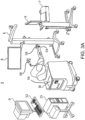
- an embodiment of a surgical system 5 for surgical applications includes a computer assisted navigation system 7, a tracking device 8, a computer 15, a display device 9 (or multiple display devices 9), and a robotic arm 30.
- the robotic arm 30 can be used in an interactive manner by a surgeon to perform a surgical procedure on a patient, such as a hip replacement procedure.
- the robotic arm 30 includes a base 32, an articulated arm 34, a force system (not shown), and a controller (not shown).
- a surgical tool 58 e.g., a rotary burring device as seen in FIG. 3A , an end effector 40 having an operating member as seen in FIG. 3B
- the surgeon manipulates the surgical tool 58 by grasping and manually moving the articulated arm 34 and/or the surgical tool.
- the force system and controller are configured to provide control or guidance to the surgeon during manipulation of the surgical tool.
- the force system is configured to provide at least some force to the surgical tool via the articulated arm 34, and the controller is programmed to generate control signals for controlling the force system.
- the force system includes actuators and a backdriveable transmission that provide haptic (or force) feedback to constrain or inhibit the surgeon from manually moving the surgical tool beyond predefined virtual boundaries defined by haptic objects as described, for example, in U.S. patent application Ser. No. 11/357,197 (Pub. No. US 2006/0142657), filed Feb. 21, 2006 , and/or U.S. patent application Ser. No. 12/654,519, filed Dec.
- the surgical system is the RIO TM .
- Robotic Arm Interactive Orthopedic System manufactured by MAKO Surgical Corp. of Fort Lauderdale, Fla.
- the force system and controller may be housed within the robotic arm 30, or may be part of an autonomous or handheld unit.
- the method of surgical registration may be done with a robotic arm of a surgical robot operating autonomously, or being guided by a surgeon under haptic controls.
- the method of surgical registration may be done via a handheld unit operating within a permissible zone of operation.
- the tracking device 8 is configured to track the relative locations of the surgical tool 58 (coupled to the robotic arm 30) and the patient's anatomy.
- the surgical tool 58 can be tracked directly by the tracking device 8.
- the pose of the surgical tool can be determined by tracking the location of the base 32 of the robotic arm 30 and calculating the pose of the surgical tool 58 based on joint encoder data from joints of the robotic arm 30 and a known geometric relationship between the surgical tool and the robotic arm 30.
- the tracking device 8 e.g., an optical, mechanical, electromagnetic, or other known tracking system
- the robotic arm 30 may include a device marker 48 to track a global or gross position of the robotic arm 30, a tool end marker 54 to track the distal end of the articulating arm 34, and a free-hand navigation probe 56 for use in the registration process.
- a device marker 48 to track a global or gross position of the robotic arm 30, a tool end marker 54 to track the distal end of the articulating arm 34, and a free-hand navigation probe 56 for use in the registration process.
- Each of these markers 48, 54, 56 (among others such as navigation markers positioned in the patient's bone) is trackable by the tracking device 8 with optical cameras, for example.
- FIG. 3B depicts an end effector 40 particularly suited for use in robotic assisted hip arthroplasty.
- the end effector 40 is configured to be mounted to an end of the robotic arm 30.
- the end effector 40 includes a mounting portion 50, a housing, a coupling device, and a release member.
- the end effector 40 is configured to individually and interchangeably support and accurately position multiple operating members relative to the robotic arm 30.
- the end effector 40 is coupled to an operating member 100.
- the end effector 40 and related tools, systems, and methods are described in U.S. Patent Application No. 12/894,071, filed September 29, 2010 , which is hereby incorporated by reference in its entirety.
- the mounting portion (or mount) 50 preferably couples the end effector 40 to the robotic arm 30.
- the mounting portion 50 extends from the housing and is configured to couple the end effector 40 to a corresponding mounting portion 35 of the robotic arm 30 using, for example, mechanical fasteners, such that the mounting portions are fixed relative to one another.
- the mounting portion 50 can be attached to the housing or formed integrally with the housing and is configured to accurately and repeatedly position the end effector 40 relative to the robotic arm 30.
- the mounting portion 50 is a semi-kinematic mount as described in U.S. patent application Ser. No. 12/644,964, filed Dec. 22, 2009 , and hereby incorporated by reference herein in its entirety.
- the CT scan or data from the CT scan is segmented and to obtain a three dimensional model 512 of the pelvis 12 and a three dimensional model 514 of the femur 14.
- the three dimensional models 512, 514 are used by the surgeon to construct a surgical plan.
- the surgeon generates a surgical plan by designating a desired pose (i.e., position and orientation) of the acetabular component and the femoral component relative to the models 512, 514 of the patient's anatomy.
- a planned pose 500 of the acetabular cup can be designated and displayed on a computer display, such as the display device 9.
- FIG. 5 illustrates an embodiment of intra-operative steps of performing a total hip replacement.
- steps S1-S7, S9, S11, and S12 can be performed with or without robotic assistance.
- S1-S2 may not be required
- S3-S5 could be done before S1-S2
- S7 could be done at any point before S8.
- Steps S8 and S10 are preferably performed using the robotic arm 30.
- step S8 (reaming) can be performed using the robotic arm 30 of FIG. 3 with the end effector 40 coupled to the operating member 100
- step S10 impacting
- Step 1006 of FIG. 10 includes moving the burr of the end effector (or other tool attached to the end of the end effector) down (distally) the femoral canal and picking, logging, or capturing points on intact bone surfaces on the inner portion of the bone.
- the bone surface may also be detected automatically by monitoring the state of the motors in the system to determine when contact with a hard surface is made.
- the iterative closest point (ICP) calculation is run with combined new and existing point-cloud data.
- the registration transform is then updated.
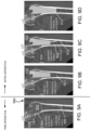
- the surgeon extends the burr 1114 through the undercut haptic volume 1110 till the burr 1114 contacts the inner bone surface 1106.
- the surgeon captures, logs, or picks points 1116 on the inner bone surface 1106.
- Step 1008 of FIG. 10 includes finishing the resection of the femoral canal to the planned resection volume or haptic volume for the placement of the stem of the femoral implant component using the updated bone registration transform. As seen in FIG. 11D , the femoral canal is fully resected to the full resection volume 1112 accord to the surgical plan.
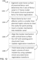
- the registration method 1200 may include, at step 1202, segmenting an outer bone surface of the proximal femur, and determining the femoral canal axis or the femoral anatomic Z-axis of the femur canal in a bone model constructed from medical images of the proximal femur. Additionally, step 1202 may include picking a point-cloud on the proximal femur outer surface for bone registration. This particular femur registration method 1200 does not include segmentation of the inner bone surface. As seen in FIG.
- the initial volume 1310 is less than the full resection volume 1312 that will be used for the implantation of the stem of the femoral implant component.
- a tracker mechanism or tool 1314 is inserted into the femoral canal.
- the tracker mechanism 1314 includes a distal expansion mechanism, a shaft extending proximally from the distal positioning mechanism, and a tracker at a proximal end of the tracker mechanism.
- the tracker mechanism 1314 may be inserted into the femoral canal such that the distal positioning mechanism extends past the initial volume 1310 and into the bone of the femoral canal.
- the plurality of members may have a plurality of markers capable of being seen under medical imaging to verify the plurality of members are contacting the cortical bone surfaces of the femur.
- the shaft extending proximally from the distal positioning mechanism is parallel to the femoral anatomic Z-axis 1306.
- the location of the bone contact points may be tracked inside the tracker mechanism 1314.
- the mechanism 1314 may include two, three, or more contact points capable of centering the tool in the canal so as to register the center point at any given position. In such an instance, a tool axis may not be needed.
- the contact points on the tracker mechanism 1314 could be spring expandable, and actively track and map the internal walls of the bone as the tool is inserted into the canal.
- the registration method 1200 at step 1206 may also include running an iterative closest point (ICP) calculation with the existing point-cloud and the femoral anatomic Z-axis determination, and the registration transform may be updated accordingly.
- ICP iterative closest point
- Step 1208 of FIG. 12 may include finishing the bone preparation by removing the tracker mechanism 1314 and resecting the remaining portion of the femoral canal to the final resection volume, which may have been updated based on the registration transform.
- the proximal femur 1302 may be fully resected to the final resection volume 1316 for the implantation of the stem of the femoral implant component.
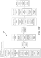
- the registration method 1330 may include the following operations or steps.
- the method 1330 may include planning the placement of an implant relative to a computer model of a patient bone in an imaging coordinate system (1).
- the implant plan in (1) may provide the planned initial femur canal preparation (2a) (to be used in canal registration) and the planned full preparation (2b) (to receive an implant stem) in the imaging coordinate system since the two planned preparations of the femoral canal may be related to the overall implant plan.
- a difference e.g., volume difference
- the full (2b) and canal (2a) preparation can also be calculated in the imaging space (2c).
- the surgeon may register the proximal femur (3) using any known registration method.
- the proximal registration transform to bone coordinate system (Bone CS A) is calculated (4).
- the planned femur canal preparation from (2) is transformed to the Bone CS A (5).
- the system can then prepare the canal in Bone CS A (6) by physically burring out the proximal canal of the femur according to the planned canal preparation determined in (2a).
- the surgeon may then registers the inner bone (7) which is now exposed by the burring.
- the proximal registration in (3) may be combined with the inner bone registration in (7), to calculate a full bone registration transformation to Bone CS B (8).
- the full bone transformation from (8) the full bone preparation plan from (2a) is transformed to Bone CS B (9).
- the decision box in 10 defines where the design may be split between full preparation or remaining preparation only.
- instance #1 Prepare full bone preparation (ignoring previously prepared canal). Knowing the full preparation plan in Bone CS B from (9), the system can then prepare the proximal femur according to the full preparation plan in Bone CS B (11) by physically burring out the proximal femoral canal according to the full preparation plan from (2b). Registration and preparation of the bone is complete in this first instance.
- Instance #3 Preparing remaining bone without transform correction.
- the planned remaining bone from (2c) is transformed into Bone CS B knowing the transform from (8).
- the system can then prepare the assumed remaining bone in Bone CS B (17) with the assumption that the differences between Bone CS A and Bone CS B are minimal and any unprepared bone due to the difference will be floating and removable from the canal. Registration and preparation of the bone is complete in this third instance.
- a surgical plan can be determined to achieve the final implant position and orientation. For instance, the final implant position and orientation will determine the corresponding position and orientation of bone to be removed from the canal of the femur so the stem of the femoral implant can be accurately positioned therein in order to achieve the desired or planned final implant position and orientation.
- the method 1340 may also include planning or determining an initial canal preparation plan, at step 1344.
- the initial canal preparation plan may be also be called a first bone removal plan of the surgical plan.
- the femoral canal will be prepared by, for example, being bored longitudinally in the place where the stem of the femoral implant will eventually be positioned.
- the femoral canal will be prepared in at least two steps: initial canal preparation for registration purposes; and final canal preparation for implantation of the femoral implant.
- the step 1344 of determining an initial canal preparation plan may include determining coordinate locations for a partial bone removal of the femoral canal.
- the step 1344 may also include determining a cut path for a surgical device to facilitate removal of the bone from the femoral canal.
- the coordinate locations and the cut path may be defined in a coordinate system relative to preoperative bone model used for planning the final implant position and orientation.
- the initial canal preparation plan may only include a partial canal preparation that includes less bone removal (e.g., less depth, less diameter) than a full canal preparation needed for implantation of the stem of the femoral implant.
- the preoperative planning of the bone removal may be split into at least a first bone removal plan including a plan for partial removal of bone from the femoral canal (for registration purposes), and a second bone removal plan including a plan for full removal of bone from the femoral canal to achieve the final implant position and orientation that was preoperatively planned.
- the next step 1346 of the method 1340 may include planning or determining a final canal preparation plan.
- the final canal preparation plan may be also be called a second bone removal plan of the surgical plan.
- the final canal preparation plan may be called a post-registration canal preparation plan.
- This step 136 of the method 1340 includes a plan for the preparation of the femoral canal beyond the initial canal preparation from step 1344.
- this step 1346 includes the plan for preparation of the femoral canal so the canal is sufficiently bored out to receive the stem of the femoral implant.
- the step 1346 may include a number of sub-steps such as the following: planning a broachless femoral preparation plan, at step 1348; planning a single broach preparation plan, at step 1350; planning an entire canal preparation plan, at step 1352; and planning only a bone remainder canal preparation plan, at step 1354.
- sub-steps such as the following: planning a broachless femoral preparation plan, at step 1348; planning a single broach preparation plan, at step 1350; planning an entire canal preparation plan, at step 1352; and planning only a bone remainder canal preparation plan, at step 1354.
- the method may include a broachless preparation plan, at step 1348.
- the femoral canal is planned to be prepared fully robotically without manual broaching by a surgeon. In this way, no portion of the bone is left for manual preparation by the surgeon; stated differently, the entire final preparation plan (whether entire canal prep or bone remainder canal prep only) is robotically prepared.
- the final canal preparation plan may include a single broach preparation plan, at step 1350.
- the femoral canal is planned to be prepared partially by robotic control, with a final broach performed manually by a surgeon.
- a surgeon may use a series of broaches of increasing size to prepare the femoral canal.
- a final (single) broach may be utilized since the final canal preparation plan was performed robotically without the need for broaches. Permitting the surgeon to perform a final broach of the femoral canal enables the surgeon to make any final adjustments to implant fit, and may also lessen the chance of removal of too much bone from the canal via robotic preparation since the surgeon could trial the implant fit while broaching.
- the final canal preparation plan 1346 may also include a determination of whether to plan the preparation of the entire femoral canal (including bone removal from the area of the initial canal preparation), at step 1352, or whether to plan the preparation of only the bone remainder of the bone canal (bone that was not removed by the initial canal preparation), at step 1354.
- the final canal preparation plan may include planning the preparation of the entire femoral canal. This may include preparation of the femoral canal that was previously prepared by the initial canal preparation plan.
- a second registration will have taken place that includes more registration data as compared to the first registration (e.g., registration data from both the inner canal and exterior surface of femur), possibly increasing the accuracy of the mapping of the surgical plan from the preoperative coordinate system including the second bone removal plan to the operative coordinate system.
- the planning for the preparation of the entire femoral canal may include planning coordinate locations for bone removal of the remaining portions of bone sufficient for implantation of the stem of the femoral implant. It is noted that a final canal preparation plan that includes the preparation of the entire femoral canal according to step 1352 may include a broachless preparation plan according to step 1348 or a single broach preparation plan according to step 1350.
- the final canal preparation plan may include planning the preparation of only the bone remainder of the femoral canal. This may include preparation of the femoral canal that was not previously prepared by the initial canal preparation plan. In certain instances, there may not be significant accuracy improvement from the second registration; therefore, the increased time it takes to re-prepare the bone as done in the entire canal preparation plan, at step 1352, may not be worth marginal increase in accuracy. If there was, however, a substantial increase in accuracy improvement from the second registration, this may indicate that preparation of the entire canal is beneficial.
- the planning for the preparation of only the bone remainder of the femoral canal, at step 1354, may include planning coordinate locations for bone removal of the remaining portions of bone sufficient for implantation of the stem of the femoral implant. It is noted that a final canal preparation plan that includes the preparation of only the bone remainder of the femoral canal according to step 1354 may include a broachless preparation plan according to step 1348 or a single broach preparation plan according to step 1350.
- the final canal preparation plan may include a plan to prepare the entire femoral canal, according to step 1352, and with a broachless preparation plan, according to step 1348.
- the final canal preparation plan may include a plan to prepare the entire femoral canal, according to step 1352, and with a single broach preparation plan, according to step 1350.
- the final canal preparation plan may include a plan to prepare only the bone remainder of the femoral canal, according to step 1354, and with a broachless preparation plan, according to step 1348.
- the final canal preparation plan may include a plan to prepare only the bone remainder of the femoral canal, according to step 1354, and with a single broach preparation plan, according to step 1350.
- a femoral track may be installed or coupled to the patient bone, at step 1356.
- the femoral tracker provides a reference to the surgical navigation system so that the surgical robot is spatially aware of the proximity of the patient's bone in the operative coordinate system.
- the proximal bone of the femur is registered (assuming it is already dislocated from the hip), at step 1358.
- the femoral head may be registered by collecting, logging, capturing points with a surgical device (e.g., tracked pointer, end effector of robotic arm) on the exterior surface of the femoral head.
- the captured points also known as registration data
- the surgical navigation system is capable of spatially locating the captured points relative to the femoral tracker.
- the internal canal preparation plan is defined relative to the preoperative bone model that represents the patient's femur.
- the goal of registration is to accurately transform or map the preoperative surgical plan (e.g., internal canal preparation plan) to the operative coordinate space relative to the actual femur in the same position and orientation that the surgical plan was in relation to the preoperative bone model.
- the surgical robotic arm and the surgical plan will be in the same coordinate system, and the robotic arm can be operated to perform the surgical plan on the actual patient bone so as to accomplish the preparation of the femur as planned preoperatively at step 1342.
- the cortical bone is much harder than the spongy bone leading to the cortical bone; thus, it is easily identified during the procedure.
- the inner cortical bone is also easily identified in the preoperative bone model. Therefore, the inner cortical bone provides areas for registration that can be combined with the registration points on the proximal femur.
- the combined points may be advantageous for producing a more accurate registration transform since the points are spaced apart from each other, and are on different surfaces of the bone (inner and outer). Registration of the proximal femur and central canal is possible since the femoral head is still intact (i.e., not yet resected).
- the method 1340 may include registering the inner canal, at step 1366.
- the inner canal may be registered in any number of ways.
- a surgical device e.g., tracked probe, end effector of surgical arm, any of the devices previously described
- a surgical device e.g., tracked probe, end effector of surgical arm, any of the devices previously described
- a surgical device e.g., tracked probe, end effector of surgical arm, any of the devices previously described
- Orientation data may be an axis, such as a longitudinal axis of the femoral canal.
- the captured points and/or the orientation data may be defined as registration data.
- the registration data may be stored as a point-cloud of data in a computer.
- the method 1340 may include calculating a registration transform using the registration data from the femoral canal (e.g., captured points) and the registration data from the exterior surface of the proximal femur (e.g., captured points and/or orientation data). Since the second registration transform, at step 1368, includes additional data from the inner canal, as compared to the first registration, at step 1360, the registration transform may have improved accuracy as compared with the first registration transform.
- the method 1340 may include transforming or mapping the final canal preparation plan, from step 1346, to the operative coordinate system based on the calculated registration transform of step 1368.
- This step maps the coordinate locations and/or instructions for bone removal for the final canal preparation plan from the preoperative coordinate system to the operative coordinate system in the same position and orientation as the surgical plan was oriented and positioned relative to the preoperative bone model. In this way, the final canal preparation plan is in the operative coordinate system with the patient's femur and the surgical robot.
- the initial canal preparation was only a partial preparation of the femoral canal for the purpose of registration of the bone surfaces or axes associated with the canal.
- the final preparation of the femur canal is to remove sufficient bone to receive the stem of the femoral implant.
- the entire canal preparation may take advantage of the second registration that involves data from the exterior and interior portions of the femur.
- the entire femur preparation may still remove bone from the initially prepared portion of the femur since the coordinates may have changed due to the subsequent registration.
- the physical preparation of the bone remainder will take place at step 1376.
- the bone remainder or portion of the femur canal that was not previously removed is prepared (i.e., removed) in order to make way for the stem of the femoral implant. This may include milling down into the femoral canal only the portions of bone that were not previously removed.
- This step may include a substep 1378 of deciding whether to use the first registration transform that was calculated with points on the exterior of the proximal femur, or the second registration transform that was calculated with points on the exterior of the proximal femur and femoral canal data taken from the femoral canal.
- the system may register a surgical device, such as a surgical robot, and a bone of a patient, such as a femur.
- the femur may include an exterior surface such as the femoral head, neck, and greater trochanter.
- the femur may also include an inner canal or femoral canal.
- the surgical device and the femur are in the same operative coordinate system (e.g., operating room).
- the system may include at least one computing device in communication with a surgical navigation system and the surgical device.
- the at least one computing device may then: c) transform the first bone removal plan of the surgical plan to the operative coordinate system based on the first registration transform. This step may correspond to step 1362 of the method 1340 of FIG. 13F .
- the at least one computing device may also: d) receive internal bone canal registration data corresponding to at least one of location or orientation data from the inner canal of the femur. This step may correspond to step 1366 of the method 1340 of FIG. 13F .
- the surgeon may capture, collect, or log points on the patient's inner femoral canal that was partially prepared for the purpose of accessing and registering to provide additional registration data that can be used for the final preparation of the femur canal.
- the exemplary system described in the previous paragraphs may be additionally or alternatively described as a computer implemented method of registration of a surgical device and a patient bone (e.g. femur).
- the computer implemented method may include the steps described by the at least one computer in steps a) through f), among others.
- the exemplary system described in the previous paragraphs may also be additionally or alternatively described as one or more tangible computer-readable storage media storing computer-executable instructions for performing a computer process on a computing system, such as the at least one computing device described in the previous paragraphs.
- the computer process may include the steps a) through f), among others, described with reference to the at least one computing device.
- an acetabular tracking array is attached to the pelvis 12 to enable the tracking device 8 to track motion of the pelvis 12.
- a checkpoint may be attached to the pelvis 12 for use during the surgical procedure to verify that the acetabular tracking array has not moved in relation to the pelvis 12.
- the checkpoint can be, for example, a checkpoint as described in U.S. patent application Ser. No. 11/750,807 (Pub. No. US 2008/0004633), filed May 18, 2007 , and hereby incorporated by reference herein in its entirety.
- step S6 the pelvis 12 is registered to correlate the pose of the pelvis 12 (physical space) with the three dimensional model 512 of the pelvis 12 in the navigation system 7 (image space).
- registration is accomplished using the tracked navigation probe 56 to collect points on the pelvis 12 (physical space) that are then matched to corresponding points on the three dimensional model 512 of the pelvis 12 (image space).
- registration may be accomplished using a tool that is coupled to the end effector 40 of the robotic arm 30.
- registration may be accomplished with any tool or device that is tracked with the navigation system 7.
- the display device 9 may show the representation 512 of the pelvis 12, including one or more registration points 516.
- the registration points 516 help the surgeon understand where on the actual anatomy to collect points with the tracked probe.
- the registration points 516 can be color coded to further aid the surgeon. For example, a registration point 516 on the pelvis 12 to be collected next with the tracked probe can be colored yellow, while registration points 516 that have already been collected can be colored green and registration points 516 that will be subsequently collected can be colored red.
- the display device 9 can show the surgeon how well the registration algorithm fit the physically collected points to the representation 512 of the pelvis 12.
- error points 518 can be displayed to illustrate how much error exists in the registration between the surface of the representation 512 and the corresponding surface of the physical pelvis 12.
- the error points 518 can be color coded, for example, with error points 518 representing minimal error displayed in green and error points 518 representing increasing amounts of error displayed in blue, yellow, and red.
- error points 518 representing different degrees of error could have different shapes or sizes.
- Verification points 519 can also be displayed. The verification points 519 illustrate to the surgeon where to collect points with the tracked probe to verify the registration.
- the software of the navigation system 7 displays the error (e.g., numerically in millimeters) between the actual point collected on the anatomy and the registered location of the representation 512 in physical space. If the registration error is too high, the surgeon re-registers the pelvis 12 by repeating the registration process of step S6.
- the error e.g., numerically in millimeters
- This type of registration method requires the surgeon to continually switch his or her focus from the display device 9 showing the representation 512 of the pelvis 12, including one or more registration points 516, to the patient's physical pelvis 12 in order to collect accurate points. Switching focus takes time, and accurately estimating where the registration points 516 are on the patient's physical pelvis 12 takes even more time. In such a registration method described in this section, it may take at least forty-three points to complete an accurate registration.
- Additional pelvic registrations methods S6 involving determining a center of rotation of the acetabulum based on pre-operative images and intra-operative point collection are described in related application PCT/US2017/049466, filed August 30, 2017 , which is hereby incorporated by reference in its entirety into the present application.
- the methods described may reduce the total number of collected points as compared with the previously described registration method. For example, with the method described in this section, a surgeon may complete an accurate registration with thirty-two points or less. Additionally, much of the registration described in this section is a region-based point collection, as opposed to a point-based point collection.
- a region-based point collection the surgeon is permitted to collect points within a region of the patient's bone, as opposed to an exact point as identified on the three dimensional bone model 512. This permits the surgeon to focus on the patient's anatomy, and collect points within the permitted region on the bone without having to switch his or her focus to the display screen 9 and back to the patient's physical pelvis 12. Collecting points within a permitted region increases accuracy as it is easier for the surgeon to collect points within a region encompassing many possible locations of permissible points, as compared with a single permissible point.
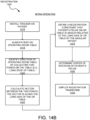
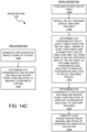
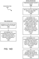
- FIGS. 14A-14B and 15A-15C illustrates a pelvic registration method 1400 utilizing acetabular center of rotation data and patient positioning data from the patient during a pre-operative image scan (e.g., CT, MRI) and while in the operating room. More particularly, the registration method 1400 assumes an orientation of a patient lying, for example, supine on an imaging table for a pre-operative image scan (e.g., CT, MRI) is the same or similar to an orientation of the same patient lying in the same position (e.g., supine in this example) on an operating room table.
- a pre-operative image scan e.g., CT, MRI
- This patient orientation data or patient positioning data may be used in conjunction with acetabular center of rotation data, among other data, that may be determined from the pre-operative image scans and from capturing points on the patient's acetabulum intra-operatively in registering a three-dimensional bone model of the patient's pelvis with the patient's physical pelvis in the operating room.
- the registration method 1400 may include generating pre-operative image scans of a patient.
- the image scans may be generated via a variety of imaging modalities including computed tomography (CT), magnetic resonance imaging (MRI), and X-ray, among others.
- CT computed tomography
- MRI magnetic resonance imaging
- X-ray X-ray
- a patient 1500 lying supine on an imaging table 1502 may be imaged via an imaging arm 1504 of an imaging machine 1506, as seen in FIG. 15A .
- the image scans may be segmented along the bone contour lines of the images.
- a three-dimensional bone model of the diseased area (e.g., ilium and femur) may be generated from the segmented image scans, at step 1406 of FIG. 14A .
- a generic 3D bone model or statistical 3D bone model being representative of the patient bone may be generated.
- Steps 1408, 1410, and 1412 may refer to the patient positioning data portion of the registration method 1400, whereas step 1414 may refer to the center of rotation calculation portion of the method 1400.
- the Z-axis, long axis, or superior-inferior axis may be identified from the scanned images or from the three-dimensional bone model.
- the Z-axis 1508 extends longitudinally down the table and from the patient's 1500 head to toes.
- the Z-axis 1508 may be identified in the scanned images as the axis the imaging table 1502 extends relative to the imaging arm 1504.
- the imaging table 1502 may be motorized so as to translate the table 1502 and patient 1500 positioned thereon along the Z-axis 1508 through an opening or through-way 1510 of the imaging arm 1504. In this orientation, the scans may be oriented perpendicular to the Z-axis 1508.
- the Z-axis 1508 may be identified in a coordinate system with the bone model.
- the registration method 1400 may include determining a pelvic axis 1512 (or a reference vector) of the patient 1500 from the scanned images or the bone model.
- the pelvic axis 1512 may be an axis bisecting the patient's pelvis between the pubic symphysis and generally equidistant between the pair of anterior superior iliac spines on the opposing ilium.
- Various methods described herein or known in the art may be used to determine the pelvic axis 1512.
- the registration method 1400 may include determining an angular offset between the Z-axis 1508 and the pelvic axis 1512.
- the angular offset 1514 may be seen in FIG. 15C , which will be discussed subsequently.
- the registration method 1400 may include determining a center of rotation of the acetabulum from the bone model. Determining the center of rotation may be done by any method described herein or any method known in the art.
- An example method of determining a center of rotation of a patient's acetabulum in a bone model generated from pre-operative images is described in PCT/ US2017/049466, filed August 30, 2017 , which is hereby incorporated by reference in its entirety into the present application.
- Another example method of determining a center of rotation of a patient's acetabulum is via a kinematic analysis or motion analysis of the patient's femur relative to the pelvis.
- the registration method 1400 may include installing a tracker on the patient's pelvis.
- the patient 1500 is in an operating room, lying supine on an operating room table 1520.
- the patient 1500 may also lay in a lateral decubitus position on the table 1520, and it can reasonably be assumed that going from supine to lateral decubitus is approximately a pure rotation about the long axis of the patient 1500.
- a robotic arm 1518 may be situated proximate the operating room table 1520.
- the tracker 1516 may be installed on the diseased side of the pelvis.
- the registration method 1400 may include positioning or aligning the patient 1500 on the operating room table 1520, as seen in FIG. 15B , in the same orientation as the patient was lying on the imaging table 1502.
- the registration method 1400 may include collecting two points 1522 on the operating room table 1520 along the long edge 1524 of the table 1520.
- a vector 1526 may be calculated between the two points 1522, at step 1422 of the method 1400. This vector 1526 may be analogous to the Z-axis 1508 of the scanned images in that the patient 1500 is lying in a supine position in likely the same orientation on the imaging table 1502 and the operating room table 1520.
- the vector 1526 may be determined and saved by the system in a common coordinate system with the positioning data for the tracker 1516. Additionally or alternatively, a pointer or tracked probe may be used to identify the table axis. For instance, the pointer may be positioned in space so it is aligned with the long edge 1524 of the table 1520, and the system may capture the axis of the pointer. Additionally or alternatively, the pointer could be aligned with the patient by, for example, placing the pointer along the midline of the patient with the pointed tip facing the patient's head. This method would also work with the patient lying on his or her side.
- Step 1424 of the registration method 1400 of FIG. 14B may include defining a registration constraint that the patient's pelvis, on the operating room table 1520, is angled relative to the vector 1526 (or the long axis of the OR table 1520) by the angular offset 1514 as shown in FIG. 15C .
- the angular offset 1514 may be defined as an angle between the Z-axis 1508 and the pelvic axis 1512, or the angular offset 1514 may be defined as an angle between the vector 1526 on the OR table 1520 and the pelvic axis 1512 (assuming the vector 1526 and the pelvic axis 1512 are in a common coordinate system).
- the registration method 1400 may include determining a center of rotation of the patient's pelvis.
- the center of rotation 1528 is shown in FIG. 15B .
- This step 1426 may be accomplished via any method known in the art, and may be accomplished via the method described in PCT/US2017/049466, filed August 30, 2017 , which is hereby incorporated by reference in its entirety into the present application.
- the method describes picking points on the patient's acetabulum and forming a sphere based on the points. From the sphere, a center of rotation can be determined.
- the registration transform may be employed at step 1428 of FIG. 14B .
- the registration transform merges the bone model (determined from pre-operative image scans of the patient's body) with the patient's physical body on the operating room table 1520 such that the robotic arm 1518 of FIG. 15C may be used to operate on the patient's body in a controlled manner and according to a pre-determined plan.
- the registration transform may use the registration constraint, of step 1428, by locking the orientation of the patient's pelvis relative to the vector 1526 during registration. Since the vector 1526 includes coordinates in three directions (x,y,z), the orientation of the pelvis may be determined when combining the information from the vector 1526 and the center of rotation 1528.
- FIGS. 14C and 15D-15E illustrate a flowchart showing exemplary steps in a surgical registration method 1440.
- FIG. 15D illustrates an overhead view of a patient 1500 on an imaging table 1502 about to undergo an imaging event (e.g., CT, MRI).
- FIG. 15E illustrates the patient 1500 on an operating room table 1520 about to undergo a surgical procedure.
- the registration method 1440 takes information about the pre-operative position and orientation of the patient 1500 on the imaging table 1502 and assumes certain information about the position and orientation of the patient will be consistent when the patient lies on the operating room table 1520.
- the COR of the acetabulum may be identified by a user selecting the COR within the image scans, for example, by selecting the COR in multiple coordinate views (e.g., coronal, sagittal, axial). Additionally or alternatively, the method 1440 may include generating a three-dimensional bone model of the patient bone either from the image scans, a statistical bone model, or generic bone model, among others. And, any method known in the art or described herein may be used to identify the COR from the bone model within the imaging coordinate system. It is noted, the COR may be a three-dimensional location (x, y, z) of one or more points relative to an origin (0, 0, 0) of the imaging coordinate system.
- a pelvic tracking device anatomy tracker 1516 is attached to the patient's diseased pelvis.
- the XYZ coordinates of the operating room table 1520 are identified. More particularly, at least three points 1530, 1532, 1534 are identified on the table 1520, where two points 1530, 1532 are located on the same side of the table (e.g., edge of the table so as to be at the same point on the x-axis), and one point 1534 is located on the opposite side of the table 1520.
- the two points 1530, 1532 may be oriented or aligned with the OR table axis or Z-axis, as shown in FIG. 15E . All points 1530, 1532, and 1534 may be positioned at the same position along the y-axis.
- the three points 1530, 1532, 1534 may be positioned at the same height relative to a plane defined by the top of the OR table 1520.
- the three points 1530, 1532, 1534 may be captured or logged with a tracked pointer of the system, and may be identified relative to the position of the pelvic tracking device 1516 in the intra-operative coordinate system.
- the table axes (x, y, z) may be determined by translating the table in order along the corresponding axes to ascertain the applicable vectors. In certain instances, it may be advantageous to determine the points 1530, 1532 prior to extensive leg manipulation to ensure the patient has not moved (e.g., before femoral dislocation).
- points 1530, 1532, and 1534 located on the OR table 1520 and the COR of the patient's acetabulum.
- points 1530, 1532, and 1534 located on the OR table 1520 and the COR of the patient's acetabulum.
- points 1534 located on the OR table 1520 and the COR of the patient's acetabulum.
- points 1534 located on the OR table 1520 and the COR of the patient's acetabulum.
- pre-operative imaging coordinate system COR of the acetabulum, as well as the coordinate axes (x, y, z), which correlate to the translational movement of the imaging table 1502.
- a six degree-of-freedom (DOF) transform is computed between the imaging coordinate points and the intra-operative coordinate points so as to register the pre-operative images to the intra-operative position of the patient 1500.
- DOF degree-of-freedom
- FIGS. 14D and 15F-15G illustrate a flowchart showing exemplary steps in a surgical registration method 1460.
- FIG. 15F illustrates an overhead view of a patient 1500 on an imaging table 1502 about to undergo an imaging event (e.g., CT, MRI).
- FIG. 15G illustrates the patient 1500 on an operating room table 1520 about to undergo a surgical procedure.
- the registration method 1460 takes information about the pre-operative position and orientation of the patient 1500 on the imaging table 1502 and assumes certain information about the position and orientation of the patient will be consistent when the patient lies on the operating room table 1520.
- the COR of the acetabulum may be identified by a user selecting the COR within the image scans, for example, by selecting the COR in multiple coordinate views (e.g., coronal, sagittal, axial). Additionally or alternatively, the method 1460 may include generating a three-dimensional bone model of the patient bone either from the image scans, a statistical bone model, or generic bone model, among others. And, any method known in the art or described herein may be used to identify the COR from the bone model within the imaging coordinate system. It is noted, the COR may be a three-dimensional location (x, y, z) of one or more points relative to an origin (0, 0, 0) of the imaging coordinate system.
- the XYZ coordinates of the acetabulum center point may be determined in the intra-operative coordinate system (relative to the anatomical tracker 1516, or another point.
- the COR may be determined based on any method described herein or known in the art. In certain instances, the COR may be determined from a range of motion analysis. In certain instances, the COR may be determined based on a point-picking approach after the femoral head is dislocated from the acetabulum.
- the robotic arm 30 may be registered at step S7.
- the robotic arm 30 is registered to correlate the pose of the robotic arm 30 (physical space) with the navigation system 7 (image space).
- the robotic arm 30 can be registered, for example, as described in U.S. patent application Ser. No. 11/357,197 (Pub. No. US 2006/0142657), filed Feb. 21, 2006 , and hereby incorporated by reference herein in its entirety.
- the surgeon can use the robotic arm 30 of FIG. 3B to facilitate a joint replacement procedure, such as reaming bone and implanting an acetabular cup for a total hip replacement or hip resurfacing procedure.
- the robotic arm 30 includes a surgical tool configured to be coupled to a cutting element (for reaming) and to engage a prosthetic component (for impacting).
- a cutting element for reaming
- a prosthetic component for impacting
- the end effector 40 can couple to the operating member 100, which couples to a cutting element.
- the end effector 40 can couple to another operating member, which engages the prosthetic component.
- the robotic arm 30 can be used to ensure proper positioning during reaming and impacting.
- step S8 of FIG. 5 the surgeon resurfaces the acetabulum 22 using a reamer, such as the operating member 100, coupled to the robotic arm 30 of FIG. 3B .
- a reamer such as the operating member 100
- the surgeon couples the appropriate operating member (e.g., a straight or offset reamer) to the end effector 40, connects the cutting element to the received operating member, and manually manipulates the robotic arm 30 to ream the acetabulum 22.
- the robotic arm 30 provides haptic (force feedback) guidance to the surgeon.
- the haptic guidance constrains the surgeon's ability to manually move the surgical tool to ensure that the actual bone cuts correspond in shape and location to planned bone cuts (i.e., cuts consistent with the surgical plan).
- an autonomous or hand held system may work within a defined virtual boundary without haptic feedback or guidance.
- step S9 of FIG. 5 the surgeon verifies that the registration (i.e., the geometric relationship) between the acetabular tracking array and the pelvis 12 is still valid by contacting the pelvis checkpoint with a tracked probe as described, for example, in U.S. patent application Ser. No. 11/750,807 (Pub. No. US 2008/0004633), filed May 18, 2007 , and hereby incorporated by reference herein in its entirety. If registration has degraded (e.g., because the acetabular tracking array was bumped during reaming), the pelvis 12 is re-registered. Registration verification can be performed any time the surgeon wants to check the integrity of the acetabular registration.
- step S10 of FIG. 5 the prosthetic component 316 is implanted on the reamed acetabulum 22 using an impactor tool.
- the display device 9 can show the planned pose 500, the activation region 510, the representations 512, 514 of the anatomy, and a representation of the surgical tool, as seen in FIG. 4 .
- the controller can initiate automatic control of the surgical tool to substantially align at least one aspect of the actual pose with the corresponding desired aspect of the target pose.
- step S11 of FIG. 5 the surgeon installs the femoral component on the femur 14, and in step S12, the surgeon determines leg length and femoral offset.
- the display device 9 can show data related to progress and/or outcome.
- data relating to the actual position of the reamed acetabulum 22 (or the implanted acetabular cup) can include, for example, numerical data representing error between the actual and planned locations in the three orthogonal planes of the patient's anatomy (i.e., medial/lateral, superior/inferior, and anterior/posterior).
- Point-picking based bone registration is one method of registration in navigated and robotic assisted orthopedic surgeries.
- an incision is made at the surgical site (e.g., hip, knee).
- a localization pointer or tracked probe is utilized to pick a digitized point-cloud (a set of data points in a coordinate system representing a surface contour) on boney areas of the patient's body that are accessible through the incision.
- ICP point-pair and iterative closest point
- the patient point-cloud data in "tracker space” coordinate system with position data corresponding to trackers on the patient body and the point-cloud of patient collected points
- An accurate registration transform is determined as the minimum root-mean-square of the point-cloud fitting.
- the surgeon may need to make an additional incision (e.g., stab incision) remote from the initial incision for the sole purpose of contacting a tracked probe or localization pointer against the patient's bone(s).
- additional incisions into the patient's body may not be ideal as there is an increased chance of infection, pain, scarring, and time associated with such a method.
- Described herein in reference to FIGS. 16A-16C are registration tools and methods for use in zones of the patient's body that are remote from the surgical site (i.e., outside the surgical incision) and that do not involve additional incisions in the patient's skin.
- needles 1 of varying lengths and diameters, such as an acupuncture needle or a syringe needle, may be used to digitize points on hard bone surface without incision though the patient's skin.
- the needle 1 diameter may be small enough to easily penetrate patient skin, the soft tissue, and the cartilage of the patient with no side effect on patient satisfaction.
- bone registration points can be picked in anatomic regions which are normally not accessible through in-wound point picking method, especially in MIS.
- one or more needles 1a may be inserted into soft tissue 7 through one of a plurality of holes of a needle fixture or template 2.
- the needle fixture 2 may guide the needles 1a through the skin, and the needles 1a may stop at the hard bone surface of the femur 6.
- a passive or active localization marker may be attached to the needles 1a so as to navigate the position of the needle-top via one or more cameras 10 (e.g., optical camera).
- a needle tracker 3a may be coupled to the needle fixture 2. However, a needle tracker 3a may not be needed if the needle tips are tracked.
- the fixture 2 may have multiple functions, including: (1) compressing the soft tissue; (2) guiding insertion of the needles 1a; and (3) measuring the position of the needle tip relative to the needle tracker 3a via a transform 8a.
- a bone tracker 4 may be rigidly attached to a hard bone surface of the femur 6 by a clamp and bone pin 5.
- a needle tip position in bone tracker 4 space may be determined through a transform 9a.
- the needle fixture 2, together with needle tracker 3a, can be freely moved to different anatomical locations of the bone to digitize multiple points on bone surface 6, and add those points to the point-cloud.
- the camera 10 may track the position of the bone tracker 4 and the needle tracker 3a.
- a proximal end of a needle 1b is attached to a mechanical tracker 3b so as to navigate the position of needle tip (distal end of needle) in mechanical tracker 3b space through transform 8b.
- the mechanical tracker 3b may be attached to the bone clamp 5 or another reference position.
- the mechanical tracker 3b may be registered to an optical tracker 4 by transform 9b.
- Mechanical tracker 3b may indicate the position of each joint - such as via encoders, or fiber optic trackers.
- a camera e.g., optical camera
- a needle tip position in bone tracker 4 space is further determined through transform 9b.
- the needle fixture 2 and tip-center point (TCP) of mechanical tracker 3b can be freely moved to different anatomical locations of the bone to digitize multiple points on the bone surfaces 6, and add those points to the point-cloud.
- FIGS. 17A-17C a registration system 1700 may be utilized as seen in FIGS. 17A-17C.
- FIG. 17A shows an anterior view of a femur 4 being registered with the registration system 1700 in a total hip arthroplasty context
- FIG. 17B shows an anterior view of the femur 4 being registered with the registration system 1700 in a total knee arthroplasty context
- FIG. 17C shows an anterior view of a tibia 5 being registered with the registration system 1700 in a total knee arthroplasty context.
- the proximal end of the femur 4 may be subject to point-picking via a tracked pointer through the incision in the patient at the surgical site (e.g., hip region).
- the femoral head may be exposed and easily accessible for point-picking via the tracked pointer for developing a point-cloud of data to be used in the registration process.
- the registration system 1700 including a needle template 2 including a plurality of through-holes, a needle tracker 3, and a tracking needle 1a are used on the shaft of the femur 4 approximately midway between the proximal femoral head and the distal femoral condyles.
- the needle template 2 may be pressed against the patient's skin, and the needle template 2 may be used to guide one or more needles 1a into the patient's skin until it contacts the bone surface of the femur.
- the optical camera (not shown) may sense the position of the needle template 2, and the corresponding position of the needle within one of the through-holes of the template 2.
- the system may use point-cloud data associated with surface points on the femoral head and on a mid-distal femoral bone surface to increase the accuracy of the process.
- the distal end of the femur 4 may be subject to point-picking via a tracked pointer through the incision in the patient at the surgical site (e.g., knee region).
- the femoral condyles may be exposed and easily accessible for point-picking via the tracked pointer for developing a point-cloud of data to be used in the registration process.
- the registration system 1700 including a needle template 2 including a plurality of through-holes, a needle tracker 3, and a tracking needle 1a are used on the shaft of the femur 4 approximately midway between the proximal femoral head and the distal femoral condyles.
- the needle template 2 may be pressed against the patient's skin, and the needle template 2 may be used to guide the needle 1a into the patient's skin until it contacts the bone surface of the femur.
- the optical camera (not shown) may sense the position of the needle template 2, and the corresponding position of the needle within one of the through-holes of the template 2.
- the system may use point-cloud data associated with surface points on the femoral condyles and on a mid-distal femoral bone surface to increase the accuracy of the process.
- the proximal end of the tibia 5 may be subject to point-picking via a tracked pointer through the incision in the patient at the surgical site (e.g., knee region).
- the proximal tibia e.g., tibial plateau
- the tracked pointer for developing a point-cloud of data to be used in the registration process.
- the registration system 1700 including a needle template 2 including a plurality of through-holes, a needle tracker 3, and a tracking needle 1a are used on the shaft of the tibia 5 approximately midway between the proximal tibia and the distal tibia.
- the needle template 2 may be pressed against the patient's skin, and the needle template 2 may be used to guide the needle 1a into the patient's skin until it contacts the bone surface of the tibia.
- the optical camera (not shown) may sense the position of the needle template 2, and the corresponding position of the needle within one of the through-holes of the template 2.
- the system may use point-cloud data associated with surface points on the proximal tibia and on a mid-distal tibial bone surface to increase the accuracy of the process.
- the registration system 1700 described with reference to FIGS. 17A-17C may be employed on the ilium, as seen in FIG. 18 .
- the acetabular rim 2 and acetabular articular surface 1 may be accessible in a hip arthroplasty procedure; but, the iliac crest 4, and an area just inferior to the lip of the iliac crest (i.e., the portion of the dorsus ossis ilium between the iliac crest 4 and the anterior gluteal line) is generally not within the surgical incision for conventional hip arthroplasty procedures.
- the articular surface 1 and the rim 2 of the acetabular may be point-picked via a tracked pointer through the incision in the hip region.
- the system may determine a center of rotation COR by, for example, the method described in PCT/US2017/049466, filed August 30, 2017 , which is hereby incorporated by reference in its entirety into the present application.
- the registration system 1700 including a needle template 2 including a plurality of through-holes, a needle tracker 3, and a tracking needle 1a are used on the iliac crest proximate the anterior superior iliac spine.
- the needle template 2 may be pressed against the patient's skin, and the needle template 2 may be used to guide the needle 1a into the patient's skin until it contacts the bone surface of the ilium.
- the optical camera (not shown) may sense the position of the needle template 2, and the corresponding position of the needle within one of the through-holes of the template 2.
- the system may use point-cloud data associated with surface points on the acetabular region of the ilium and on the iliac crest surface to increase the accuracy of the process.
- the registration system 1700 may additionally or alternatively be used on other parts of the patient's body that may be segmented, such as the spine (L1, L2, L3, L4, L5). As seen in FIG. 19A , which is a side view of an ilium and a spinal column, a tracking array may be positioned on the patient's ilium. Additionally, the registration system 1700 including a needle template 2 including a plurality of through-holes, a needle tracker 3, and a tracking needle 1a may be used on the boney portions of the posterior aspect of the vertebrae of the spine. The needle template 2 may be pressed against the patient's skin, and the needle template 2 may be used to guide the needle 1a into the patient's skin until it contacts the bone surface of the vertebrae. The optical camera (not shown) may sense the position of the needle template 2, and the corresponding position of the needle within one of the through-holes of the template 2.
- the system may use point-cloud data associated with the vertebrae, along with another registration area, to increase the accuracy of the process.
- the method described herein may be utilized on any bone, and is not limited to bones of the legs and vertebrae.
- the needle based registration method may be used on bones of the arms, hands, feet, upper body, and head, without limitation.
- FIGS. 20A-20D depict, respectively, an axial cross-section image of a vertebra 2000 and a bone anchor 2002 positioned therein, an axial cross-section image of a vertebra 2000 with a rotating burr 2004 positioned partially within the vertebra 2000, another axial cross-section image of a vertebra 2000 with a rotating burr 2004 positioned partially within the vertebra 2000, and an axial cross-section image of a burr 2004 extending through a vertebra 2000 to a far inner wall of the cortical bone 2006.
- a tracker device is placed in the pelvis of the patient so the vertebrae (which is the subject of a surgical procedure) could be several non-rigid joints away from the tracker.
- the vertebrae which is the subject of a surgical procedure
- working on adjacent vertebral segments may move the spine slightly.
- FIG. 20A shows an axial cross-section image of a vertebra 2000 with a bone anchor 2002 positioned therein.
- a shank 2008 of the bone anchor 2002 extends through a pedicle 2010 of the vertebra 2000 while avoiding contact with the spinal cord 2012.
- the vertebra 2000 includes cortical bone 2006 (compact bone) on outer portions or outer shell including a cortical rim 2014 surrounding the vertebral body, and cancellous bone 2016 (spongy or trabecular bone) interior of the cortical bone 2006.
- cortical bone 2006 is harder and denser than the cancellous bone 2016, which is porous, weaker, and easier to fracture than cortical bone 2006.
- Cancellous bone 2016 makes up the shafts of long bones (e.g., femur, tibia). Cortical bone 2006 surrounds and protects the spinal cord 2012.
- the surgeon When inserting a bone anchor 2002 into a vertebra 2000, as seen in FIG. 20A , the surgeon attempts to position the anchor 2002 as shown in the figure where the shank 2008 remains within the vertebra 2000 (i.e., does not exit either side of the cortical bone 2006). That is, the shank 2008 remains within the cancellous bone 2016 once it initially penetrates through the cortical bone 2006.
- Conventional ways to ensure placement of the shank 2008 within the interior of the vertebra 2000 is for a surgeon to drill through the outer cortical layer of the vertebra 2000 in the vicinity of the pedicle 2010 and attempt to identify an inner surface of the cortical surface or wall by the "feel" of the tip of the drill bit contacting the inner cortical surface. Once the surgeon senses contact with the inner wall of the cortical bone 2006, the surgeon knows not to extend the drill any farther.
- the point of contact between the bone and the burr 2004 may be used to update the registration of the bone position.
- the surgeon may also update the screw insertion plan if needed.
- Registration improvement may be optimized by the load cell 2020 detecting the direction of the contact of the burr 2004 with the bone.
- the system may identify an error by comparing the contact position with the anticipated contact based upon the surgical navigation system tracking the position of the burr 2004 with respect to the registered position of the patient. If there is a difference, the registration could be updated using the contact point as an internal registration point.
- FIGS. 20B-20D illustrate a system and method of registering a vertebra 2000 using a burr 2004 of an end effector 2018 of surgical robotic system (not shown in FIGS. 20B-20D , but as shown and described in this application).
- the burr 2004 may be used to create a pathway into the pedicle 2010. Once inside the bone, the burr 2004 may be shut off so as to cease rotating. The surgeon may advance the burr 2004 through the cancellous bone 2016.
- a load cell 2020 on the end effector 2018 would be able to indicate if the burr 2004 contacts cortical bone 2006.
- the load cell 2020 may be configured so as to identify and distinguish cancellous bone 2016 from cortical bone 2006 as each bone type has a different stiffness.
- the load cell 2020 may audibly or otherwise (visually, haptic) signal the burr's 2004 contact with the cortical bone 2006.
- haptic the surgical robotic system may prevent the surgeon from extending the burr 2004 further in a direction of the cortical bone 2006 once a certain stiffness value is reached.
- the surgeon may insert the burr 2004 into the pedicle 2010 into the smallest neck region between the cortical bone 2006 around the spinal cord 2012 and the cortical canal 2022 around the exterior of the vertebra 2000.
- the burr 2004 may be moved from side-to-side (as indicated by the arrows in FIG. 20B ) to intentionally contact the cortical walls 2006 and register the internal features thereof.
- the burr 2004 may be pivoted about the entry point in order to minimize any disruption of screw thread purchase areas.
- the surgeon may insert the burr 2004 into the pedicle 2010 into the smallest neck region between the cortical bone 2006 around the spinal cord 2012 and the cortical con around the exterior of the vertebra 2000.
- the burr 2004 may be moved (as indicated by the arrows in FIG. 20C ) over the internal surface of the cortical canal 2022 to map out or create a registration surface thereon.
- the identified surface on the cortical con may then be compared with the model to improve or adjust registration.
- the surgeon may insert the burr 2004 through the pedicle 2010 and through the cancellous bone 2016 until the burr 2004 contacts a far inner surface of the cortical rim 2014. If there were no contacts with the burr 2004 against the cortical bone 2006 of the neck region of the pedicle 2012, contact with the inner surface of the cortical rim 2014 would be confirmed. When the load cell 2020 detects the far cortex, then the system may indicate such contact and the registration may be updated or improved accordingly.
- the system may also detect potential breaches of the cortical bone 2006. For example, once the burr 2004 contacts the cortical bone 2006, as determined by the load experienced by the load cell 2020 of the end effector 2018, any loads experienced at that boundary wall that vary from the previous loads (e.g., a sudden decrease in resistance/stiffness indicating a break though of the cortical wall) may be considered potential breaches of the cortical surface 2006.
- a system and method of surgical registration may be as follows.
- a system may register patient data gathered intra-operatively of a vertebra 2000 with a computer model of the vertebra in a coordinate system.
- the vertebra 2000 may include a cortical bone shell 2006 having an outer surface and an inner surface, and cancellous bone interior 2016 of the cortical bone shell 2006.
- the vertebra 2000 may define a spinal cord canal 2022 bounded by the cortical bone shell 2006.
- the system may include a surgical navigation system, and at least one computing device.
- the surgical navigation system may include a tracking device and at least one tool 2018 that is tracked by the tracking device.
- the at least one tool may include an end effector 2018 having a cutting element 2004 at a distal end thereof, and a load cell 2018 to sense a load on the cutting element 2004.
- the computing device may be in communication with the surgical navigation system. And the at least one computing device may store the computer model of the vertebra in the coordinate system.
- the at least one computing device may receive load data associated with a load experienced by the cutting element 2004 at the distal end of the end effector 2018 when the cutting element 2004 contacts the cortical bone shell 2006 and the cancellous bone 2016.
- the at least one computing device may also identify, based on the load data, when the cutting element 2004 contacts the inner surface of the cortical bone shell 2006.
- the at least one computing device may also receive a point-cloud of data associated with the vertebra 2000.
- the point-cloud of data may include coordinate locations on the inner surface of the cortical bone shell 2006 that are collected via the cutting element 2004.
- the at least one computing device may also run or update a transform to register the point-cloud of data associated with the vertebra 2000 to the computer model of the vertebra in a common coordinate system.
- the computing system 3000 may be applicable to any of the computers or systems utilized in the preoperative or intra-operative planning of the arthroplasty procedure (e.g., registration), and other computing or network devices. It will be appreciated that specific implementations of these devices may be of differing possible specific computing architectures not all of which are specifically discussed herein but will be understood by those of ordinary skill in the art.
- the computer system 3000 may be a computing system that is capable of executing a computer program product to execute a computer process. Data and program files may be input to the computer system 3000, which reads the files and executes the programs therein. Some of the elements of the computer system 3000 are shown in FIG. 21 , including one or more hardware processors 3002, one or more data storage devices 3004, one or more memory devices 3008, and/or one or more ports 3008-3010. Additionally, other elements that will be recognized by those skilled in the art may be included in the computing system 3000 but are not explicitly depicted in FIG. 21 or discussed further herein. Various elements of the computer system 3000 may communicate with one another by way of one or more communication buses, point-to-point communication paths, or other communication means not explicitly depicted in FIG. 21 .
- the processor 3002 may include, for example, a central processing unit (CPU), a microprocessor, a microcontroller, a digital signal processor (DSP), and/or one or more internal levels of cache. There may be one or more processors 3002, such that the processor 3002 comprises a single central-processing unit, or a plurality of processing units capable of executing instructions and performing operations in parallel with each other, commonly referred to as a parallel processing environment.
- CPU central processing unit
- DSP digital signal processor
- the computer system 3000 may be a conventional computer, a distributed computer, or any other type of computer, such as one or more external computers made available via a cloud computing architecture.
- the presently described technology is optionally implemented in software stored on the data stored device(s) 3004, stored on the memory device(s) 3006, and/or communicated via one or more of the ports 3008-3010, thereby transforming the computer system 3000 in FIG. 21 to a special purpose machine for implementing the operations described herein.
- Examples of the computer system 3000 include personal computers, terminals, workstations, mobile phones, tablets, laptops, personal computers, multimedia consoles, gaming consoles, set top boxes, and the like.
- Machine-readable media may include any tangible non-transitory medium that is capable of storing or encoding instructions to perform any one or more of the operations of the present disclosure for execution by a machine or that is capable of storing or encoding data structures and/or modules utilized by or associated with such instructions.
- Machine-readable media may include a single medium or multiple media (e.g., a centralized or distributed database, and/or associated caches and servers) that store the one or more executable instructions or data structures.
- One or more such communication interface devices may be utilized via the communication port 3010 to communicate one or more other machines, either directly over a point-to-point communication path, over a wide area network (WAN) (e.g., the Internet), over a local area network (LAN), over a cellular (e.g., third generation (3G) or fourth generation (4G)) network, or over another communication means.
- WAN wide area network
- LAN local area network
- cellular e.g., third generation (3G) or fourth generation (4G) network
- the communication port 3010 may communicate with an antenna or other link for electromagnetic signal transmission and/or reception.
- the second data point may correspond in location to a second virtual data point on the computer model.
- the intra-operative center of rotation may correspond to a physical center of rotation of the second bone relative to the first bone.
Landscapes
- Health & Medical Sciences (AREA)
- Engineering & Computer Science (AREA)
- Life Sciences & Earth Sciences (AREA)
- Surgery (AREA)
- Public Health (AREA)
- General Health & Medical Sciences (AREA)
- Medical Informatics (AREA)
- Biomedical Technology (AREA)
- Animal Behavior & Ethology (AREA)
- Heart & Thoracic Surgery (AREA)
- Veterinary Medicine (AREA)
- Nuclear Medicine, Radiotherapy & Molecular Imaging (AREA)
- Molecular Biology (AREA)
- Robotics (AREA)
- Orthopedic Medicine & Surgery (AREA)
- Oral & Maxillofacial Surgery (AREA)
- Transplantation (AREA)
- Pathology (AREA)
- Epidemiology (AREA)
- Primary Health Care (AREA)
- Dentistry (AREA)
- Cardiology (AREA)
- Vascular Medicine (AREA)
- Physical Education & Sports Medicine (AREA)
- Databases & Information Systems (AREA)
- Data Mining & Analysis (AREA)
- Urology & Nephrology (AREA)
- Human Computer Interaction (AREA)
- Surgical Instruments (AREA)
- Prostheses (AREA)
- Instructional Devices (AREA)
- Saccharide Compounds (AREA)
- Medical Treatment And Welfare Office Work (AREA)
Applications Claiming Priority (3)
| Application Number | Priority Date | Filing Date | Title |
|---|---|---|---|
| US201962814057P | 2019-03-05 | 2019-03-05 | |
| EP20766825.2A EP3934519B1 (de) | 2019-03-05 | 2020-03-05 | Systeme zur chirurgischen registrierung |
| PCT/US2020/021173 WO2020181076A1 (en) | 2019-03-05 | 2020-03-05 | Systems and methods for surgical registration |
Related Parent Applications (2)
| Application Number | Title | Priority Date | Filing Date |
|---|---|---|---|
| EP20766825.2A Division EP3934519B1 (de) | 2019-03-05 | 2020-03-05 | Systeme zur chirurgischen registrierung |
| EP20766825.2A Division-Into EP3934519B1 (de) | 2019-03-05 | 2020-03-05 | Systeme zur chirurgischen registrierung |
Publications (2)
| Publication Number | Publication Date |
|---|---|
| EP4576120A2 true EP4576120A2 (de) | 2025-06-25 |
| EP4576120A3 EP4576120A3 (de) | 2025-08-20 |
Family
ID=72336719
Family Applications (2)
| Application Number | Title | Priority Date | Filing Date |
|---|---|---|---|
| EP25174882.8A Pending EP4576120A3 (de) | 2019-03-05 | 2020-03-05 | System und verfahren zur chirurgischen registrierung |
| EP20766825.2A Active EP3934519B1 (de) | 2019-03-05 | 2020-03-05 | Systeme zur chirurgischen registrierung |
Family Applications After (1)
| Application Number | Title | Priority Date | Filing Date |
|---|---|---|---|
| EP20766825.2A Active EP3934519B1 (de) | 2019-03-05 | 2020-03-05 | Systeme zur chirurgischen registrierung |
Country Status (7)
| Country | Link |
|---|---|
| US (3) | US11839551B2 (de) |
| EP (2) | EP4576120A3 (de) |
| JP (4) | JP7280967B2 (de) |
| KR (1) | KR102711269B1 (de) |
| CN (2) | CN118697470A (de) |
| AU (3) | AU2020232318B2 (de) |
| WO (1) | WO2020181076A1 (de) |
Families Citing this family (26)
| Publication number | Priority date | Publication date | Assignee | Title |
|---|---|---|---|---|
| CN114466625B (zh) * | 2019-10-03 | 2026-04-10 | 史密夫和内修有限公司 | 全膝关节置换翻修术期间的髓内管的配准 |
| US11816831B2 (en) | 2020-04-29 | 2023-11-14 | Medtronic Navigation, Inc. | System and method for navigating and illustrating a procedure |
| US11890060B2 (en) | 2020-04-29 | 2024-02-06 | Medtronic Navigation, Inc. | System and method for navigating and illustrating a procedure |
| CN116528786B (zh) * | 2020-10-27 | 2026-01-30 | 马科外科公司 | 基于超声的多重骨配准手术系统及在计算机辅助手术中的使用方法 |
| US12193940B2 (en) * | 2021-02-11 | 2025-01-14 | Depuy Ireland Unlimited Company | Customized implant and method |
| CN113116523B (zh) * | 2021-04-09 | 2022-02-11 | 骨圣元化机器人(深圳)有限公司 | 骨科手术配准装置、终端设备和存储介质 |
| CN113616350B (zh) * | 2021-07-16 | 2022-04-19 | 元化智能科技(深圳)有限公司 | 标记点选取位置的验证方法、装置、终端设备和存储介质 |
| CN113842213B (zh) * | 2021-09-03 | 2022-10-11 | 北京长木谷医疗科技有限公司 | 手术机器人导航定位方法及系统 |
| EP4366662A4 (de) * | 2021-09-30 | 2024-11-06 | MicroPort Orthopedics Holdings Inc. | Systeme und verfahren zur verwendung von photogrammetrie zur intraoperativen ausrichtung chirurgischer elemente |
| US12324615B2 (en) * | 2021-11-05 | 2025-06-10 | Mako Surgical Corp. | Assessment of soft tissue tension in hip procedures |
| CN114305685B (zh) * | 2021-12-17 | 2024-05-24 | 杭州键嘉医疗科技股份有限公司 | 一种用于髋关节置换手术中的髋骨配准方法 |
| KR102700171B1 (ko) * | 2022-03-16 | 2024-08-28 | 재단법인대구경북과학기술원 | 관절 내부 뼈의 이동을 반영하는 관절경 네비게이션 장치 및 방법 |
| US12419692B2 (en) | 2022-05-03 | 2025-09-23 | Mazor Robotics Ltd. | Robotic arm navigation using virtual bone mount |
| US11478314B1 (en) | 2022-06-08 | 2022-10-25 | Ix Innovation Llc | System and method for implanting smart implants using robotic telesurgery |
| CN116370015B (zh) * | 2022-07-01 | 2024-04-30 | 北京和华瑞博医疗科技有限公司 | 髋关节置换手术执行器及外科手术系统 |
| CN115239830B (zh) * | 2022-07-08 | 2025-09-16 | 苏州微创畅行机器人有限公司 | 软骨面重建方法、系统、计算机设备、介质和程序产品 |
| CN115300041B (zh) * | 2022-08-10 | 2023-03-14 | 骨圣元化机器人(深圳)有限公司 | 髋臼截骨矫形手术定位工具、系统及计算机设备 |
| CN115645050B (zh) * | 2022-11-07 | 2024-10-01 | 上海卓昕医疗科技有限公司 | 手术导航系统 |
| WO2024121622A1 (en) * | 2022-12-08 | 2024-06-13 | Stryker Australia Pty Ltd | Implant design optimization for geometric uncertainty |
| CN116630400A (zh) * | 2023-05-11 | 2023-08-22 | 邓迎生 | 基于股骨颈轴位安全靶区边界配准的空心钉首准置钉方法 |
| CN119074019A (zh) * | 2023-05-31 | 2024-12-06 | 通用电气精准医疗有限责任公司 | 医学成像方法、装置以及系统 |
| CN116439833B (zh) * | 2023-06-13 | 2023-09-12 | 北京壹点灵动科技有限公司 | 骨盆配准处理方法、装置、存储介质及电子设备 |
| CN116712171B (zh) * | 2023-08-11 | 2023-11-03 | 北京维卓致远医疗科技发展有限责任公司 | 一种粗隆间骨折导航方法、设备及可存储介质 |
| US20250248765A1 (en) * | 2024-02-01 | 2025-08-07 | Globus Medical, Inc. | Computer assisted pelvic surgery navigation |
| WO2025195646A1 (en) * | 2024-03-21 | 2025-09-25 | Smith & Nephew, Inc. | Registration of pre-operative and intra-operative data |
| US20250384570A1 (en) * | 2024-06-14 | 2025-12-18 | Globus Medical, Inc. | Patient Registration For Total Hip Arthroplasty Procedure Using Pre-Operative Computed Tomography (CT), Intra-Operative Fluoroscopy, and/Or Point Cloud Data |
Citations (3)
| Publication number | Priority date | Publication date | Assignee | Title |
|---|---|---|---|---|
| US20060142657A1 (en) | 2002-03-06 | 2006-06-29 | Mako Surgical Corporation | Haptic guidance system and method |
| US20080004633A1 (en) | 2006-05-19 | 2008-01-03 | Mako Surgical Corp. | System and method for verifying calibration of a surgical device |
| US20170049466A1 (en) | 2015-08-21 | 2017-02-23 | Schmid Healthcare Holdings, LLC | Tissue forceps |
Family Cites Families (12)
| Publication number | Priority date | Publication date | Assignee | Title |
|---|---|---|---|---|
| JPH069628Y2 (ja) * | 1989-03-03 | 1994-03-16 | 株式会社長田中央研究所 | インプラント用マイクロモーター装置 |
| US5806518A (en) * | 1995-09-11 | 1998-09-15 | Integrated Surgical Systems | Method and system for positioning surgical robot |
| US9639156B2 (en) * | 2011-12-29 | 2017-05-02 | Mako Surgical Corp. | Systems and methods for selectively activating haptic guide zones |
| US9247998B2 (en) * | 2013-03-15 | 2016-02-02 | Intellijoint Surgical Inc. | System and method for intra-operative leg position measurement |
| CN118236208A (zh) * | 2013-10-15 | 2024-06-25 | 穆罕默德·拉什万·马赫福兹 | 骨骼重建和骨外科植入物 |
| US10258256B2 (en) * | 2014-12-09 | 2019-04-16 | TechMah Medical | Bone reconstruction and orthopedic implants |
| JP6879927B2 (ja) * | 2015-03-26 | 2021-06-02 | バイオメット マニュファクチャリング,リミティド ライアビリティ カンパニー | 外科的処置を計画及び実行するシステム |
| CN111329552B (zh) * | 2016-03-12 | 2021-06-22 | P·K·朗 | 包括机器人的用于引导骨切除的增强现实可视化 |
| CA3030831A1 (en) * | 2016-07-15 | 2018-01-18 | Mako Surgical Corp. | Systems for a robotic-assisted revision procedure |
| EP3506823A4 (de) | 2016-08-30 | 2020-03-04 | MAKO Surgical Corp. | Systeme und verfahren zur intraoperativen beckenregistrierung |
| US11071594B2 (en) | 2017-03-16 | 2021-07-27 | KB Medical SA | Robotic navigation of robotic surgical systems |
| WO2018231775A1 (en) * | 2017-06-12 | 2018-12-20 | Think Surgical, Inc. | Intramedullary cutting device for revision hip arthroplasty |
-
2020
- 2020-03-05 CN CN202410836624.0A patent/CN118697470A/zh active Pending
- 2020-03-05 EP EP25174882.8A patent/EP4576120A3/de active Pending
- 2020-03-05 KR KR1020217031969A patent/KR102711269B1/ko active Active
- 2020-03-05 JP JP2021552670A patent/JP7280967B2/ja active Active
- 2020-03-05 EP EP20766825.2A patent/EP3934519B1/de active Active
- 2020-03-05 CN CN202080033313.0A patent/CN113993445B/zh active Active
- 2020-03-05 US US16/810,283 patent/US11839551B2/en active Active
- 2020-03-05 WO PCT/US2020/021173 patent/WO2020181076A1/en not_active Ceased
- 2020-03-05 AU AU2020232318A patent/AU2020232318B2/en active Active
-
2023
- 2023-05-12 JP JP2023079394A patent/JP7553651B2/ja active Active
- 2023-07-25 AU AU2023208089A patent/AU2023208089B2/en active Active
- 2023-10-16 US US18/380,488 patent/US12403019B2/en active Active
-
2024
- 2024-09-05 JP JP2024153269A patent/JP7766758B2/ja active Active
-
2025
- 2025-04-17 AU AU2025202751A patent/AU2025202751A1/en active Pending
- 2025-08-04 US US19/289,902 patent/US20250352358A1/en active Pending
- 2025-10-28 JP JP2025181678A patent/JP2026012284A/ja active Pending
Patent Citations (3)
| Publication number | Priority date | Publication date | Assignee | Title |
|---|---|---|---|---|
| US20060142657A1 (en) | 2002-03-06 | 2006-06-29 | Mako Surgical Corporation | Haptic guidance system and method |
| US20080004633A1 (en) | 2006-05-19 | 2008-01-03 | Mako Surgical Corp. | System and method for verifying calibration of a surgical device |
| US20170049466A1 (en) | 2015-08-21 | 2017-02-23 | Schmid Healthcare Holdings, LLC | Tissue forceps |
Also Published As
| Publication number | Publication date |
|---|---|
| AU2020232318B2 (en) | 2023-04-27 |
| AU2025202751A1 (en) | 2025-05-08 |
| AU2023208089B2 (en) | 2025-01-23 |
| CN118697470A (zh) | 2024-09-27 |
| US12403019B2 (en) | 2025-09-02 |
| AU2023208089A1 (en) | 2023-08-17 |
| KR20210137500A (ko) | 2021-11-17 |
| JP2022524752A (ja) | 2022-05-10 |
| EP4576120A3 (de) | 2025-08-20 |
| JP7766758B2 (ja) | 2025-11-10 |
| EP3934519A1 (de) | 2022-01-12 |
| US11839551B2 (en) | 2023-12-12 |
| US20200281742A1 (en) | 2020-09-10 |
| CN113993445A (zh) | 2022-01-28 |
| CN113993445B (zh) | 2024-07-09 |
| US20250352358A1 (en) | 2025-11-20 |
| JP2023091040A (ja) | 2023-06-29 |
| EP3934519B1 (de) | 2025-06-11 |
| US20240041613A1 (en) | 2024-02-08 |
| JP7280967B2 (ja) | 2023-05-24 |
| JP7553651B2 (ja) | 2024-09-18 |
| AU2020232318A1 (en) | 2021-09-02 |
| KR102711269B1 (ko) | 2024-09-27 |
| JP2024166255A (ja) | 2024-11-28 |
| WO2020181076A1 (en) | 2020-09-10 |
| EP3934519A4 (de) | 2022-11-23 |
| JP2026012284A (ja) | 2026-01-23 |
Similar Documents
| Publication | Publication Date | Title |
|---|---|---|
| AU2023208089B2 (en) | Systems and methods for surgical registration | |
| US12343088B2 (en) | Lower extremities leg length calculation method | |
| US11813052B2 (en) | Systems and methods for intra-operative pelvic registration | |
| US11737894B2 (en) | Registration tools, systems, and methods |
Legal Events
| Date | Code | Title | Description |
|---|---|---|---|
| PUAI | Public reference made under article 153(3) epc to a published international application that has entered the european phase |
Free format text: ORIGINAL CODE: 0009012 |
|
| STAA | Information on the status of an ep patent application or granted ep patent |
Free format text: STATUS: THE APPLICATION HAS BEEN PUBLISHED |
|
| AC | Divisional application: reference to earlier application |
Ref document number: 3934519 Country of ref document: EP Kind code of ref document: P |
|
| AK | Designated contracting states |
Kind code of ref document: A2 Designated state(s): AL AT BE BG CH CY CZ DE DK EE ES FI FR GB GR HR HU IE IS IT LI LT LU LV MC MK MT NL NO PL PT RO RS SE SI SK SM TR |
|
| REG | Reference to a national code |
Ref country code: DE Ref legal event code: R079 Free format text: PREVIOUS MAIN CLASS: G16H0050500000 Ipc: A61B0005000000 |
|
| PUAL | Search report despatched |
Free format text: ORIGINAL CODE: 0009013 |
|
| AK | Designated contracting states |
Kind code of ref document: A3 Designated state(s): AL AT BE BG CH CY CZ DE DK EE ES FI FR GB GR HR HU IE IS IT LI LT LU LV MC MK MT NL NO PL PT RO RS SE SI SK SM TR |
|
| RIC1 | Information provided on ipc code assigned before grant |
Ipc: A61B 5/00 20060101AFI20250715BHEP Ipc: A61B 34/20 20160101ALI20250715BHEP Ipc: A61B 34/10 20160101ALI20250715BHEP Ipc: A61B 34/30 20160101ALI20250715BHEP Ipc: A61B 17/34 20060101ALI20250715BHEP Ipc: A61B 34/00 20160101ALI20250715BHEP Ipc: A61B 90/50 20160101ALI20250715BHEP Ipc: A61B 90/00 20160101ALI20250715BHEP Ipc: A61F 2/46 20060101ALN20250715BHEP |
|
| STAA | Information on the status of an ep patent application or granted ep patent |
Free format text: STATUS: REQUEST FOR EXAMINATION WAS MADE |
|
| 17P | Request for examination filed |
Effective date: 20260211 |
|
| STAA | Information on the status of an ep patent application or granted ep patent |
Free format text: STATUS: EXAMINATION IS IN PROGRESS |