EP4576132A2 - Überwachung des gesundheitszustands eines solenoids - Google Patents
Überwachung des gesundheitszustands eines solenoids Download PDFInfo
- Publication number
- EP4576132A2 EP4576132A2 EP25174221.9A EP25174221A EP4576132A2 EP 4576132 A2 EP4576132 A2 EP 4576132A2 EP 25174221 A EP25174221 A EP 25174221A EP 4576132 A2 EP4576132 A2 EP 4576132A2
- Authority
- EP
- European Patent Office
- Prior art keywords
- computer
- current
- solenoid
- solenoid valve
- instant
- Prior art date
- Legal status (The legal status is an assumption and is not a legal conclusion. Google has not performed a legal analysis and makes no representation as to the accuracy of the status listed.)
- Pending
Links
Images


Classifications
-
- F—MECHANICAL ENGINEERING; LIGHTING; HEATING; WEAPONS; BLASTING
- F16—ENGINEERING ELEMENTS AND UNITS; GENERAL MEASURES FOR PRODUCING AND MAINTAINING EFFECTIVE FUNCTIONING OF MACHINES OR INSTALLATIONS; THERMAL INSULATION IN GENERAL
- F16K—VALVES; TAPS; COCKS; ACTUATING-FLOATS; DEVICES FOR VENTING OR AERATING
- F16K37/00—Special means in or on valves or other cut-off apparatus for indicating or recording operation thereof, or for enabling an alarm to be given
- F16K37/0025—Electrical or magnetic means
- F16K37/0041—Electrical or magnetic means for measuring valve parameters
-
- F—MECHANICAL ENGINEERING; LIGHTING; HEATING; WEAPONS; BLASTING
- F16—ENGINEERING ELEMENTS AND UNITS; GENERAL MEASURES FOR PRODUCING AND MAINTAINING EFFECTIVE FUNCTIONING OF MACHINES OR INSTALLATIONS; THERMAL INSULATION IN GENERAL
- F16K—VALVES; TAPS; COCKS; ACTUATING-FLOATS; DEVICES FOR VENTING OR AERATING
- F16K31/00—Actuating devices; Operating means; Releasing devices
- F16K31/02—Actuating devices; Operating means; Releasing devices electric; magnetic
- F16K31/06—Actuating devices; Operating means; Releasing devices electric; magnetic using a magnet, e.g. diaphragm valves, cutting off by means of a liquid
- F16K31/0675—Electromagnet aspects, e.g. electric supply therefor
-
- H—ELECTRICITY
- H01—ELECTRIC ELEMENTS
- H01F—MAGNETS; INDUCTANCES; TRANSFORMERS; SELECTION OF MATERIALS FOR THEIR MAGNETIC PROPERTIES
- H01F7/00—Magnets
- H01F7/06—Electromagnets; Actuators including electromagnets
- H01F7/08—Electromagnets; Actuators including electromagnets with armatures
- H01F7/18—Circuit arrangements for obtaining desired operating characteristics, e.g. for slow operation, for sequential energisation of windings, for high-speed energisation of windings
- H01F7/1844—Monitoring or fail-safe circuits
- H01F2007/1861—Monitoring or fail-safe circuits using derivative of measured variable
Definitions
- the present invention relates to the field of solenoid valves and in particular to a method of monitoring the health status thereof.
- a solenoid valve is an electromechanically operated valve and is one of the most commonly used components in industrial applications to control fluid flow. Characteristics of solenoid valves differ in characteristics of the electric current they use, the strength of magnetic field generated, the mechanism they use to regulate a fluid, and the type and characteristics of fluid they control. In other words, there are many valve designs, yet they all have one common component, namely the solenoid.
- the solenoid is an electro-mechanical actuator. It comprises a static part, the coil, and a moving part, the plunger. The interface between both parts is principally accomplished by a mechanical spring.
- the coil may be powered by a voltage source thereby realizing a linear movement of the plunger.
- the stroke length or the distance between the plunger's begin and end position, is generally small in the order of magnitude of 1mm.
- Controlling fluid flows in industrial applications means that solenoid valves tasks are to shut off, release, dose, distribute, or mix fluids. It is however important that they offer these tasks in a safe and reliable manner.
- the solenoid valve Because of its technical function, it will be unavoidable that the solenoid valve will degrade over time. Besides the quality of the solenoid valve itself, a variety of other variables will influence its lifespan like the intensity of use and/or the atmospheric conditions wherein it operates. Other influences are clogging due to fluid particles of the controlled process and working conditions such as applied pressure.
- solenoid valves To avoid any critical situation and to guarantee a proper operation of the industrial installation wherein solenoid valves are operating, it is therefore important that a malfunctioning solenoid valve is replaced as quickly as possible. Moreover, it should be avoided that a solenoid valve malfunctions, in other words, a solenoid valve should be replaced before any malfunction occurs.
- a method to avoid any critical situation is defining a maintenance interval wherein all solenoid valves of an industrial installation are replaced.
- the interval will, for example, be determined based on a total number of allowable switching operations or just be a time period expressed in working hours of the industrial installations itself.
- a disadvantage in defining the maintenance interval based on the number of allowable switches is that it has to be chosen in a very conservative manner, especially when a safe and reliable operation needs to be guaranteed. In other words, the occurrence that only one solenoid valve fails, needs to be avoided. This may result in a replacement of a whole set of solenoid valves which are still well-functioning and potentially remain well-functions for very long times and/or many more switching operations.
- the present invention aims to remedy the above-mentioned and other disadvantages.
- the present invention according to a first aspect concerns a computer-implemented method for determining a health state of a solenoid valve comprising a solenoid, the solenoid valve suitable for supporting a process control system, the method comprising the steps of:
- the solenoid comprises a coil, a plunger, and a mechanical spring.
- the coil may be powered by a voltage source thereby realizing a linear movement of the plunger.
- a current flow therein causing the movement of the plunger.
- This movement causes a state change of the solenoid valve, either into an open or closed state.
- the latter depends on the type of solenoid valve, namely either a normally open or normally closed solenoid valve. It is thus the current that causes or initiates a state change that is monitored.
- a time period indicative for the health state of the solenoid valve is determined. This time period is the time between the instant a state change is initiated and the instant that the time derivative of the monitored current is discontinue.
- the instant the current becomes discontinue can be determined accurately when the current is monitored as a continuous-time signal. This would correspond to sampling at an infinite sampling frequency or with an infinitesimal small sampling period. In practice, said instant will thus be determined indirectly because of the used practical sampling frequency and corresponding sampling period. The indirect determination will further be discussed in this disclosure of the invention.
- a voltage over the connection points of the coils is applied and an electric current starts to flow in it.
- the value of the current will not instantly be at a particular level but will be build up from zero because the coil is an inductive component.
- the current is monitored, and the time derivative is calculated, either directly or indirectly. Since the current is building up, i.e. changing over time, the time derivative is therefore also varying over time.
- the magnetic field caused by the current creates a force which moves the plunger until the solenoid valve is either open or closed. Additionally, the mechanical spring will influence the movement of the plunger as well.
- the current in the plunger is initially influenced by the applied voltage source, but further also by a set of other variables, like the movement of the plunger.
- the magnetic field generated by the coil which initially moves the plunger is itself also influenced by the position and the movement of the plunger as a result of Maxwell's equations. This means that the movements of the plunger impact the current flowing through the coil and vice versa. It should thus be clear that the value of the current over time varies, as well as its time derivative.
- the time period between an instant when a state change of the solenoid valve is initiated and an instant when the time-derivative of the current is discontinue is determined.
- the instant when a state change is initiated is, for example, the instant when an instruction is given to change the state or the instant when the current in the coil differs from zero. This instant may thus be determined as an instant when the magnitude of the current surpasses a predefined threshold. Alternatively, the state change may be determined when a command thereto is given. Additionally, the monitoring may be initiated by said command. Furthermore, note that when dealing with alternating current valves, the magnitude may be regarded as being an absolute value thereof for dealing with the occurrence when the current initiates at a negative half-period.
- this instant should be chosen in a coherent and consistent manner such that a set of determined time periods can be compared with each other.
- the other instant defining the end of the determined time period is when the time derivative is discontinue. This is thus the instant when the curve of the current has a kink or dip.
- said kink When monitoring the current at a high sampling frequency, said kink may be determined accurately, thus in a more or less direct manner. More in practice, this kink may be determined indirectly by processing the samples representing the current. A range of samples of which the values are descending, followed by a range of samples of which the values are increasing, indicates that in between said ranges the kink may be present.
- the computer-implemented method may therefore comprise the step of sampling the current thereby obtaining an array of sampled currents.
- the determining of the instant and comparing it with a reference time period may then be performed by said array of sampled currents.
- the determined time period is compared with a reference time period.
- the array of sampled currents is correlated with a reference array of the solenoid valve to determine said time period.
- Another approach to determine the time period is sequentially correlating a subarray of the array of sampled currents with a reference subarray representing a V-shaped or an L-shaped function.
- the reference time period and the determined time period may further depend on parameters such as the operational pressure. Depending on the valve type, when the operational pressure increases, the reference time period can increase, decrease or stay constant. Consequently, the drift or increase of the determined time period may depend as well on parameters such as the operational pressure.
- this polynomial model or other curve fitted model could be updated upon every switching instant a new determined time period becomes available. The difference between the updated polynomial model or curve fitted model and the ground truth becomes larger and larger over time and establishes a measure for the deterioration of the solenoid valve as well.
- the determined time period may be reported.
- the health state of the solenoid valve may be reported.
- the data representative for the instant and/or the health state may be send to another device for further processing.
- the health state may, for example, be a value between zero and one, whereby zero corresponds to a failed solenoid valve, and one corresponds to a new and healthy solenoid valve.
- the health state may be reported as 'healthy', 'degrading', or 'faulty' .
- each solenoid valve may be monitored individually. Furthermore, this may be done in a structured and automated manner. Secondly, the determining of the health state may be performed independently of the environment wherein the solenoid valves operate. In other words, this environment is indirectly considered since a quicker deterioration due to a harmful environment will be noticed by merely determining the time period as discussed above.
- a data processing apparatus comprising a processor adapted to perform the steps of the method according to the first aspect.
- the processor may be a microprocessor or a microcontroller.
- a computer program comprising instructions which, when the program is executed by a computer, cause the computer to carry out the method of the first aspect is disclosed.
- a data carrier signal carrying the computer program of the third aspect is disclosed.
- a node comprising the data processing unit apparatus according to the second aspect is disclosed together with an interface configured to represent the health state.
- a solenoid valve comprising the apparatus according to the second aspect, and/or the node according to fifth aspect is disclosed.
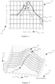
- Fig. 1 illustrates currents as a function of time of an alternating current solenoid.
- the time is represented on the abscissa 104 and the values of the current on the ordinate 105.
- the solid line 100 represents a well-functioning solenoid, this means in a healthy condition, while the dashed line 101 represents the current of the same solenoid which is after a number of switching operations malfunctioning and needs to be replaced.
- the plunger impacts the current flowing through the coil as represented by the graphs 110.
- Both currents as represented by 100 and 101 show a typical coil current on the ordinate 105 as a function of time on the abscissa 104 when being switched on to an alternating voltage source.
- the dip 102 in the pattern of current 100 in this example around 9.5ms, or 5.2ms after the switching operation which occurs on 4.3ms, is characterized by a sudden change of the current's time derivative. This dip 102 occurs at the moment the plunger hits its mechanical end position. In what happens afterwards, the solenoid can be considered as a component without a moving part, whereby the current 100 converges to a periodical pattern.
- Solenoid valves supplied by a constant voltage source reveal a similar current dip 102, yet their current eventually converges to a constant value.
- Figure 5 illustrates a typical switch-on current of a direct current solenoid.
- the dip occurs at approximately 32ms, and the current converges to the constant value of approximately 500mA.
- the claimed invention is independent of the type of solenoid, i.e. being an alternating current solenoid or direct current solenoid. For both types, the same method is, mutatis mutandis, applied for determining the health status thereof.
- the current may be measured with the use of a Hall-sensor and/or a shunt.
- the measured voltage which is proportional to the current, may be transformed by an analogue-digital-converter for further processing.
- the disclosed method monitors this dip 102, meaning that the instant this dip 102 occurs with regard to the instant of the initiating of the state change at 4.3ms is determined.
- the time period between the instant of initiating a state change of the solenoid valve and the instant when the time derivative of the current is discontinue, thus when the dip 102 occurs is 5.2ms.
- the shift 203 is amplified when the shadowing coil, responsible for keeping the plunger in its end position while the coil currents cross zero, deteriorates and/or breaks, as this results in a huge amount of repetition hits at twice the grid frequency.
- the dip remains approximately at a same position and the solenoid performs as specified by the supplier.
- the time-to-hit shows a statistical distribution with a typical mean value and a very small deviation.
- the dip starts shifting to the right the more on-off cycles have been done. Since the plunger eventually hits the end position, the plunger is definitely not blocked, and the valve might still function properly for the intended application. However, one should be aware of other potentially harmful second-order effects. For example, if the shadowing coil of an alternating current breaks - often coinciding with the start of the degradation phase - the plunger may shortly leave and return to the end position twice per cycle of the grid voltage, causing repetition hits, accelerated wear, tiny leakages and/or irritating noise.
- the time-to-hit is used as a health indicator for the solenoid.
- the solenoid As long as the distribution of the time-to-hit does not statistically deviate with some level of probability from its original distribution, the solenoid is considered healthy. The moment this condition is no longer met, the degradation phase is initiated. In some applications, this may be the right moment to replace the solenoid.
- the application allows solenoids running in the degradation phase, one can make use of the time-to-hit value to estimate the remaining useful life up to some statistical level of probability. To do so, one requires evolution curves of the time-to-hit for a multitude of identical valves, preferably in different applications, and make a statistical model of that evolution. There are various ways to statistically approach this.
- the movement of the solenoid plunger typically ends within a 10ms time interval when dealing with alternating current valves.
- the time interval may be around 30ms in a healthy state and going up to 50ms in a deteriorated state.
- a minimal sampling frequency of 10kHz is advised. Sampling at 4kHz is likewise possible when a time resolution of 0.25ms is acceptable. It should be noted that this is a trade-off between accuracy and cost of sampling.
- the current is to be sampled continuously.
- the current When unpowered, the current is theoretically zero, but its digital representation typically varies close to the lowest significant bits. Therefore, one needs to define a threshold value that is never exceeded when the solenoid is unpowered, yet that is as small as possible, e.g. 5mA.
- the solenoid upon excess of the chosen current threshold, the solenoid is for sure operating with a moving plunger in its early transient phase. This triggers the storage of all subsequent current samples in a buffer that covers a time span of at least 10ms, e.g. 100 samples at 10kHz sampling frequency, but preferably 100ms such that also direct current valves may be monitored.
- a numeric algorithm starts computing a series of correlation coefficients with a much shorter reference vector in which a V-shaped profile or L-shaped profile is typically stored.
- the goal is to define the position in the buffer for which this correlation coefficient is largest, as this is a measure for the time-to-hit.
- the bias equals the time between switching on and exceeding the threshold value and could be added to retrieve an exact value for the time-to-hit.
- Communication interface 412 may comprise any transceiver-like mechanism such as for example one or more Ethernet interfaces that enables computing system 400 to communicate with other devices and/or systems to acquire the parameters at regular intervals.
- the communication interface 412 of computing system 400 may be connected to such another computing system by means of a local area network (LAN) or a wide area network (WAN) such as for example the internet.
- Storage element interface 406 may comprise a storage interface such as for example a Serial Advanced Technology Attachment (SATA) interface or a Small Computer System Interface (SCSI) for connecting bus 410 to one or more storage elements 408, such as one or more local disks, for example SATA disk drives, and control the reading and writing of data to and/or from these storage elements 408.
- SATA Serial Advanced Technology Attachment
- SCSI Small Computer System Interface
- storage elements 408 above is described as a local disk, in general any other suitable computer-readable media such as a removable magnetic disk, optical storage media such as a CD or DVD, -ROM disk, solid state drives, flash memory cards, ... could be used.
- the system 400 described above can also run as a virtual machine above the physical hardware.
Landscapes
- Engineering & Computer Science (AREA)
- General Engineering & Computer Science (AREA)
- Physics & Mathematics (AREA)
- Electromagnetism (AREA)
- Mechanical Engineering (AREA)
- Power Engineering (AREA)
- Magnetically Actuated Valves (AREA)
- Testing And Monitoring For Control Systems (AREA)
- Details Of Valves (AREA)
- Testing Of Devices, Machine Parts, Or Other Structures Thereof (AREA)
Applications Claiming Priority (3)
| Application Number | Priority Date | Filing Date | Title |
|---|---|---|---|
| BE20215464A BE1029494B1 (nl) | 2021-06-14 | 2021-06-14 | Monitoren van een gezondheidsstatus van een actuator |
| EP22731671.8A EP4356031B1 (de) | 2021-06-14 | 2022-06-03 | Überwachung des gesundheitszustands eines solenoids |
| PCT/EP2022/065243 WO2022263211A1 (en) | 2021-06-14 | 2022-06-03 | Monitoring a health status of a solenoid |
Related Parent Applications (2)
| Application Number | Title | Priority Date | Filing Date |
|---|---|---|---|
| EP22731671.8A Division-Into EP4356031B1 (de) | 2021-06-14 | 2022-06-03 | Überwachung des gesundheitszustands eines solenoids |
| EP22731671.8A Division EP4356031B1 (de) | 2021-06-14 | 2022-06-03 | Überwachung des gesundheitszustands eines solenoids |
Publications (2)
| Publication Number | Publication Date |
|---|---|
| EP4576132A2 true EP4576132A2 (de) | 2025-06-25 |
| EP4576132A3 EP4576132A3 (de) | 2025-10-08 |
Family
ID=77447651
Family Applications (2)
| Application Number | Title | Priority Date | Filing Date |
|---|---|---|---|
| EP25174221.9A Pending EP4576132A3 (de) | 2021-06-14 | 2022-06-03 | Überwachung des gesundheitszustands eines solenoids |
| EP22731671.8A Active EP4356031B1 (de) | 2021-06-14 | 2022-06-03 | Überwachung des gesundheitszustands eines solenoids |
Family Applications After (1)
| Application Number | Title | Priority Date | Filing Date |
|---|---|---|---|
| EP22731671.8A Active EP4356031B1 (de) | 2021-06-14 | 2022-06-03 | Überwachung des gesundheitszustands eines solenoids |
Country Status (12)
| Country | Link |
|---|---|
| US (1) | US12540686B2 (de) |
| EP (2) | EP4576132A3 (de) |
| JP (1) | JP7674524B2 (de) |
| KR (1) | KR102946488B1 (de) |
| CN (1) | CN117413139A (de) |
| BE (1) | BE1029494B1 (de) |
| DK (1) | DK4356031T3 (de) |
| ES (1) | ES3052086T3 (de) |
| FI (1) | FI4356031T3 (de) |
| PL (1) | PL4356031T3 (de) |
| PT (1) | PT4356031T (de) |
| WO (1) | WO2022263211A1 (de) |
Families Citing this family (1)
| Publication number | Priority date | Publication date | Assignee | Title |
|---|---|---|---|---|
| JP2025540121A (ja) * | 2022-12-02 | 2025-12-11 | ヴァンティブ ユーエス ヘルスケア エルエルシー | 弁機能性評価を有する透析システム |
Family Cites Families (11)
| Publication number | Priority date | Publication date | Assignee | Title |
|---|---|---|---|---|
| DE29715925U1 (de) * | 1997-09-05 | 1997-10-23 | Festo AG & Co, 73734 Esslingen | Schaltungsvorrichtung |
| DE19963154B4 (de) * | 1999-12-24 | 2009-10-08 | Conti Temic Microelectronic Gmbh | Verfahren zur Vorgabe des Stroms durch ein induktives Bauteil |
| JP2002174358A (ja) | 2000-12-08 | 2002-06-21 | Smc Corp | 故障診断機能付電磁弁 |
| JP2002181220A (ja) * | 2000-12-14 | 2002-06-26 | Japan Organo Co Ltd | 電磁弁駆動回路 |
| JP5422459B2 (ja) * | 2010-03-26 | 2014-02-19 | 富士フイルム株式会社 | ラッチ式電磁バルブの動作確認装置及び方法並びにインクジェット記録装置 |
| DE102017200809A1 (de) * | 2016-12-08 | 2018-06-14 | Robert Bosch Gmbh | Verfahren und Vorrichtung zum Prüfen eines elektromagnetischen Ventils auf Fehlfunktion |
| IT201700096979A1 (it) * | 2017-08-29 | 2019-03-01 | Camozzi Automation S P A | Dispositivo e metodo di diagnostica per elettrovalvole |
| IT201700096969A1 (it) * | 2017-08-29 | 2019-03-01 | Camozzi Automation S P A | Dispositivo e metodo di diagnostica per elettrovalvole |
| US11506726B2 (en) * | 2018-08-31 | 2022-11-22 | Danfoss Power Solutions Ii Technology A/S | System and method for detecting coil faults |
| US12142423B2 (en) | 2020-05-12 | 2024-11-12 | Hitachi High-Tech Corporation | Solenoid valve abnormality detection device, automatic medical analysis apparatus using same, and solenoid valve abnormality detection method |
| US11499651B2 (en) * | 2020-06-23 | 2022-11-15 | Honeywell International Inc. | Switchless valve position detection system |
-
2021
- 2021-06-14 BE BE20215464A patent/BE1029494B1/nl active IP Right Grant
-
2022
- 2022-06-03 EP EP25174221.9A patent/EP4576132A3/de active Pending
- 2022-06-03 KR KR1020247000684A patent/KR102946488B1/ko active Active
- 2022-06-03 PT PT227316718T patent/PT4356031T/pt unknown
- 2022-06-03 JP JP2023573416A patent/JP7674524B2/ja active Active
- 2022-06-03 PL PL22731671.8T patent/PL4356031T3/pl unknown
- 2022-06-03 CN CN202280038702.1A patent/CN117413139A/zh active Pending
- 2022-06-03 US US18/564,292 patent/US12540686B2/en active Active
- 2022-06-03 FI FIEP22731671.8T patent/FI4356031T3/fi active
- 2022-06-03 EP EP22731671.8A patent/EP4356031B1/de active Active
- 2022-06-03 WO PCT/EP2022/065243 patent/WO2022263211A1/en not_active Ceased
- 2022-06-03 DK DK22731671.8T patent/DK4356031T3/da active
- 2022-06-03 ES ES22731671T patent/ES3052086T3/es active Active
Also Published As
| Publication number | Publication date |
|---|---|
| PT4356031T (pt) | 2025-09-29 |
| BE1029494A1 (nl) | 2023-01-13 |
| DK4356031T3 (da) | 2025-10-20 |
| ES3052086T3 (en) | 2025-12-30 |
| JP2024520541A (ja) | 2024-05-24 |
| FI4356031T3 (fi) | 2025-10-21 |
| KR20240021219A (ko) | 2024-02-16 |
| KR102946488B1 (ko) | 2026-03-31 |
| EP4356031A1 (de) | 2024-04-24 |
| WO2022263211A1 (en) | 2022-12-22 |
| BE1029494B1 (nl) | 2023-01-16 |
| US20240255069A1 (en) | 2024-08-01 |
| PL4356031T3 (pl) | 2025-11-24 |
| EP4356031B1 (de) | 2025-08-06 |
| US12540686B2 (en) | 2026-02-03 |
| JP7674524B2 (ja) | 2025-05-09 |
| EP4576132A3 (de) | 2025-10-08 |
| CN117413139A (zh) | 2024-01-16 |
Similar Documents
| Publication | Publication Date | Title |
|---|---|---|
| JP6611370B2 (ja) | 自動化システムの電気機械コンポーネントを監視するための方法、コンピュータプログラム、及び電気機械コンポーネント | |
| JP5015396B2 (ja) | プロセス制御ループパラメータの推定値の統計的に決定する方法 | |
| EP2297502B1 (de) | Steuerventilsystem mit cyklus überwachung, diagnostik und vorhersage der degradierung | |
| JP4685803B2 (ja) | エレベーターブレーキ制御装置 | |
| EP4356031B1 (de) | Überwachung des gesundheitszustands eines solenoids | |
| CN114867945B (zh) | 用于螺线管阀优化和响应劣化测量的系统和方法 | |
| KR101894697B1 (ko) | 고장 예지 장치 및 방법 | |
| EP1991806A2 (de) | System und verfahren zur flüssigkeitsregulierung | |
| KR102627536B1 (ko) | 밸브의 스위칭 상태를 판단하는 방법 및 솔레노이드 밸브 조립체 | |
| KR102629090B1 (ko) | 기계 학습 장치, 데이터 처리 시스템, 추론 장치 및 기계 학습 방법 | |
| US20240426910A1 (en) | Device and method for identifying wear of an electromechanical device | |
| CN114001195A (zh) | 用于阀的诊断的方法,诊断模块以及阀 | |
| US7881880B2 (en) | Actuator performance monitoring system | |
| KR102663521B1 (ko) | 스프링 가압 전자 브레이크의 예방적 기능 제어 | |
| EA049262B1 (ru) | Контроль исправности соленоида | |
| WO2004025384A1 (en) | Method and apparatus for determining hysteresis | |
| CN119617164B (zh) | 一种电动执行机构的智能控制方法及系统 | |
| US12247677B2 (en) | Method of diagnosing a valve, diagnosis module, and valve | |
| CN113939888B (zh) | 预测初级继电器故障的方法 | |
| CN111198308A (zh) | 用于获取电磁执行器的电磁线圈的剩余的运行时间的方法 | |
| CN119547028A (zh) | 用于寿命预测和监测的方法 | |
| CN113360541B (zh) | 状态估计装置、控制阀、存储介质以及状态估计方法 | |
| CN121876038A (zh) | 一种耐高温液压泵流量调节方法及系统 | |
| CN120608979A (zh) | 用于实施电磁致动部件的基于数据的位置传感器的方法、流体阀门和流体系统 | |
| WO2024020018A1 (en) | On-line valve health monitor |
Legal Events
| Date | Code | Title | Description |
|---|---|---|---|
| PUAI | Public reference made under article 153(3) epc to a published international application that has entered the european phase |
Free format text: ORIGINAL CODE: 0009012 |
|
| STAA | Information on the status of an ep patent application or granted ep patent |
Free format text: STATUS: THE APPLICATION HAS BEEN PUBLISHED |
|
| AC | Divisional application: reference to earlier application |
Ref document number: 4356031 Country of ref document: EP Kind code of ref document: P |
|
| AK | Designated contracting states |
Kind code of ref document: A2 Designated state(s): AL AT BE BG CH CY CZ DE DK EE ES FI FR GB GR HR HU IE IS IT LI LT LU LV MC MK MT NL NO PL PT RO RS SE SI SK SM TR |
|
| REG | Reference to a national code |
Ref country code: DE Ref legal event code: R079 Free format text: PREVIOUS MAIN CLASS: H01F0007180000 Ipc: F16K0037000000 |
|
| PUAL | Search report despatched |
Free format text: ORIGINAL CODE: 0009013 |
|
| AK | Designated contracting states |
Kind code of ref document: A3 Designated state(s): AL AT BE BG CH CY CZ DE DK EE ES FI FR GB GR HR HU IE IS IT LI LT LU LV MC MK MT NL NO PL PT RO RS SE SI SK SM TR |
|
| RIC1 | Information provided on ipc code assigned before grant |
Ipc: F16K 37/00 20060101AFI20250903BHEP Ipc: F16K 31/06 20060101ALI20250903BHEP |
|
| STAA | Information on the status of an ep patent application or granted ep patent |
Free format text: STATUS: REQUEST FOR EXAMINATION WAS MADE |