EP4576146A1 - Manuelle steuervorrichtung - Google Patents
Manuelle steuervorrichtung Download PDFInfo
- Publication number
- EP4576146A1 EP4576146A1 EP24221282.7A EP24221282A EP4576146A1 EP 4576146 A1 EP4576146 A1 EP 4576146A1 EP 24221282 A EP24221282 A EP 24221282A EP 4576146 A1 EP4576146 A1 EP 4576146A1
- Authority
- EP
- European Patent Office
- Prior art keywords
- support
- assembly
- switch
- control device
- zone
- Prior art date
- Legal status (The legal status is an assumption and is not a legal conclusion. Google has not performed a legal analysis and makes no representation as to the accuracy of the status listed.)
- Pending
Links
Images



Classifications
-
- H—ELECTRICITY
- H01—ELECTRIC ELEMENTS
- H01H—ELECTRIC SWITCHES; RELAYS; SELECTORS; EMERGENCY PROTECTIVE DEVICES
- H01H23/00—Tumbler or rocker switches, i.e. switches characterised by being operated by rocking an operating member in the form of a rocker button
- H01H23/28—Tumbler or rocker switches, i.e. switches characterised by being operated by rocking an operating member in the form of a rocker button with three operating positions
- H01H23/30—Tumbler or rocker switches, i.e. switches characterised by being operated by rocking an operating member in the form of a rocker button with three operating positions with stable centre positions and one or both end positions unstable
-
- H—ELECTRICITY
- H01—ELECTRIC ELEMENTS
- H01H—ELECTRIC SWITCHES; RELAYS; SELECTORS; EMERGENCY PROTECTIVE DEVICES
- H01H25/00—Switches with compound movement of handle or other operating part
- H01H25/008—Operating part movable both angularly and rectilinearly, the rectilinear movement being perpendicular to the axis of angular movement
Definitions
- the technical field of the invention relates to remote manual control, for example to control an electromechanical actuator for controlling a sun protection or blackout screen, or more generally to control home automation equipment. More particularly, the invention relates to a manual control device, in particular for such home automation equipment.
- the present invention can be applied in particular in the field of home automation.
- EP2439761A2 proposes a solution using an adapter module allowing the mechanical interface to be made between a control module and a control part, thus forming the aesthetic interface mentioned above.
- This solution is not satisfactory in the sense that it is complex to implement and has a size that is not ideal.
- the aim of the present invention is to propose a customizable manual control device, in particular simple to assemble, and preferably limited in size.
- the manual control device has great flexibility of use in the sense that the control assembly can be easily changed, for example depending on the function to be controlled (roller shutter, light or other), the electronic control module and the intermediate assembly can then remain identical. Therefore, the constraints of transmission of the support forces to the first switch are managed by the intermediate assembly which forms an adaptive interface. In addition, this makes it possible to simplify the reuse of different control assemblies and this makes it possible to simplify the production of the intermediate assembly.
- the manual control device may further include one or more of the following features.
- this allows the control assembly to vary between a stable configuration in which it does not cooperate, via the intermediate assembly, with the first switch (inactive state of the first switch) and an unstable configuration in which it cooperates, via the intermediate assembly, with the first switch (active state of the first switch).
- the manual control device in the rest state of the manual control device for which no force is exerted by the user on the control assembly, the manual control device generally adopts the same external shape.
- the intermediate assembly comprises a key having a rigid surface facing the control assembly and capable of receiving, in various parts of the surface of the rigid surface offset from each other and offset relative to a region of said surface directly above an actuating member belonging to the first switch, a pressure exerted by the control assembly when the pressure force is applied to the first pressure zone, said pressure being adapted to cause a movement of the key to act on the state of the first switch in reaction to said pressure force.
- the intermediate assembly and the control assembly are linked so that when the first support zone moves from the unstable active position to the stable inactive position, the stress induced by the return device also tends to induce a movement of said at least one rigid part of the intermediate assembly allowing the state of the first switch to move from the active state to the inactive state when the support force on the first support zone is released.
- the same return device allows, via the same request, a return of the manual control device to a neutral state in which the first switch is in its inactive state and the first support zone is in particular in its stable inactive position.
- the manual control device comprises at least one return member distinct from the return device and configured to induce, when the first switch is placed in the active state by pressing the intermediate assembly on the first switch, a stress tending to place the intermediate assembly in a configuration such that the first switch is in its inactive state.
- control assembly and the intermediate assembly can thus simply be in, or come into, contact with each other.
- the return member is integrated into the intermediate assembly or is integrated into the first switch.
- the first assembly means comprise at least two separate holes provided in the support at a distance from each other, and the control assembly comprises retaining means cooperating with said holes and comprising at least one retaining element straddled in one of said holes and at least one clipping member engaged in another of said holes.
- the control assembly comprises a central support area operable by manual application of a pressing force, by the user of the manual control device, on the control assembly so as to cause a movement of the central support zone towards the support from a stable inactive position to an unstable active position inducing the actuation of a third switch, belonging to the electronic control module, mounted on the printed circuit, the third switch being arranged to be actuated by a portion of the intermediate assembly following a deformation of the intermediate assembly caused by a pressing of the control assembly on the portion of the intermediate assembly induced by the movement of the central support zone.
- a stop function making it possible to stop a function activated by the transition, where appropriate, of the first switch or the second switch to its active state.
- control assembly comprises a housing, and the intermediate assembly is at least partly housed in said housing.
- the invention also relates to a kit for forming the manual control device.
- the kit comprises the electronic control module, the intermediate assembly and a plurality of different control assemblies each capable of being mounted to at least a portion of the first assembly means.
- the control assemblies may all be separate from the support, or only one of them may be mounted to the support.
- a manual control device 100 comprises an electronic control module 101 and a control assembly 102.
- the control assembly 102 allows interaction with the electronic control module 101, in particular by providing a user interface with which a user of the manual control device 100 can interact.
- the control assembly 102 comprises a first support zone 103 accessible from outside the manual control device 100, the first support zone 103 allowing the manual application of a support force F1 by the user of the manual control device 100.
- the electronic control module 101 comprises a support 104 delimiting an outer face 105 of the electronic control module 101.
- the support 104 can take the form of a plate.
- the support 104 comprises first assembly means 106a, 106b, 106c, at least one part of which is suitable for mounting the control assembly 102.
- the support 104 further comprises second assembly means 107.
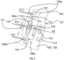
- the first and second assembly means 106a, 106b, 106c, 107 are notably visible in figures 3 And 4 for the first embodiment and in Figure 12 for the second embodiment because on these figures 3 , 4 And 12 , the control assembly 102 has been removed for reasons of understanding the assembly of the control assembly 102 to the electronic control module 101.
- the first assembly means 106a, 106b, 106c may be suitable for mounting different control assemblies 102 each of which may be selectively mounted to the first assembly means 106a, 106b, 106c or to a corresponding part of these first assembly means 106a, 106b, 106c.
- Different control assemblies 102 may use, where appropriate, different parts of the first means 106a, 106b, 106c as can be deduced from the figures 3 , 4 And 5 as well as figures 11 And 12 .
- the electronic control module 101 includes a printed circuit 108 housed inside the electronic control module 101.
- the electronic control module 101 comprises a first switch 109 capable of selectively occupying an active state and an inactive state, the first switch 109 being mounted on the printed circuit 108. In particular, the first switch 109 is turned towards the control assembly 102.
- control assembly 102 comprises a first face 118 ( figures 1 , 8 , 10 ) comprising the first support zone 103, and a second face 119 ( figures 5 And 11 ) opposite the first face 118.
- This second face 119 is turned towards the printed circuit 108, and is used in particular for mounting the control assembly 102 on the support 104.
- the manual control device 100 comprises an intermediate assembly 110 (examples of which are visible in figures 2 , 3 , 6 , 7 , 9 And 12 ) mounted to the second assembly means 107 so that at least one rigid part 111 of the intermediate assembly 110 has the ability to move according to a degree of freedom relative to the support 104.
- Said at least one rigid part 111 of the assembly 110 intermediate is arranged between the support 104 and the control assembly 102 mounted on said at least one part of the first assembly means 106a, 106b, 106c of the support 104.
- the intermediate assembly 110 is arranged between the support 104 and the control assembly 102.
- first and second assembly means 106a, 106b, 106c, 107 allows the control assembly 102 and the intermediate assembly 110 to each be mounted independently on the electronic control module 101.
- This independence makes it possible to remove the control assembly 102, for example, on a construction site, in the event of renovation, or for cleaning, while keeping the intermediate assembly 110 functional for the user in order to activate or not the first switch 109.
- This also makes it possible to access a programming button of the control device 100 which would be hidden behind the control assembly 102, while keeping the manual control device 100 functional in the sense that the first switch 109 can then be activated via the intermediate assembly 110, which can then be operated by the user.
- the actuator or electromechanical actuator is a device for rolling up or unrolling a movable screen, for example a roller shutter or a canvas blind, on a rotating shaft coupled to the actuator.
- a control order transmitted by the manual control device 100 to the actuator can then be at least one signal representative of a user instruction chosen from: lowering or deploying the movable screen (i.e. unrolling it from the rotating shaft); raising or folding the movable screen (i.e. winding it around the rotating shaft); stopping the movement of the movable screen (i.e. stopping the user instruction currently being carried out, for example lowering the movable screen or raising the movable screen).
- the electronic control module 101 can comprise several switches such as, in addition to the first switch 109 (also simply called a switch), a second switch 112 and a third switch 113 (also simply called additional switches) as will be seen later and for example illustrated in Figure 2 , each switch can be associated with a corresponding control command.
- first switch 109 also simply called a switch
- second switch 112 also simply called additional switches
- third switch 113 also simply called additional switches
- the electronic control module 101 is configured to generate the control order forming a signal representative of the user instruction corresponding to raising or folding the mobile screen when the first switch 103 changes from its inactive state to its active state.
- the support 104 is interposed, on the one hand, between the printed circuit 108 and the control assembly 102, and, on the other hand, between the printed circuit 108 and the intermediate assembly 101, then acting as a mechanical protection screen for the printed circuit 108.
- the support 104 may be a plate comprising a front face 135 and a rear face 136.
- the front face 135 corresponds in particular to the external face 105 of the electronic control module 101.
- the electronic control module 101 may comprise a housing 114 assembled against the rear face of the plate so as to delimit a closed housing in which the printed circuit 108 is housed.
- the housing 114 may house the printed circuit 108 or at least a part of the printed circuit 108.
- the housing 114 may delimit a housing 115.
- the support 104 may then be integral with the housing 114 (for example by clipping onto the housing 114) and closes the housing 115 in particular so as to oppose the removal of the printed circuit 108 from the housing 115.
- the printed circuit 108 can be positioned/arranged in the housing 115 and a face 116 of the printed circuit 108, on which the first to third switch(es) 109, 112, 113 are mounted, is in particular turned towards the support 104.
- the first switch 109 is then, preferably, arranged in the housing 115 and accessible through the support 104 via a first opening 137; this also being true, where appropriate, for the second and/or third switches 112, 113 respectively via a second opening 138 and a third opening 139 ( Figure 4 ).
- the plate comprises mounting means 151 for fixing the manual control device 100 relative to a wall of a building.
- the mounting means 151 may be formed by mounting openings provided through the plate, each comprising, for example, a screw head passage zone and a curved zone opening into the passage zone opposing the passage of the screw head. but allowing adjustment of the inclination of the plate in relation to the wall of the building.
- the manual control device 100 may be intended to be partially recessed into the wall panel.
- the mounting means 151 are mounting openings for attachment to a wall-mounted flush-mounting box, itself recessed into the wall panel, or to the wall panel directly.
- the mounting openings may, for example, be four in number, each associated with a lateral edge of the plate comprising four consecutive lateral edges laterally delimiting the plate.
- the first assembly means 106a, 106b, 106c comprise at least two separate holes, for example through holes, arranged in the support 104 at a distance from each other.
- the control assembly 102 then comprises retaining means 117a, 117b, 117c cooperating with said holes forming the first assembly means 106a, 106b, 106c.
- the retaining means 117a, 117b, 117c comprising at least one retaining element 117a, such as a grip, inserted into one of said holes 106a of the first assembly means 106a, 106b, 106c and at least one clipping member 117b, 117c, for example a clip, engaged in another of said holes 106b, 106c of the first assembly means 106a, 106b, 106c.
- the or each retaining element 117a is formed as a bracket-shaped body belonging to the control assembly 102 and projecting from the second face 119 of the control assembly 102.
- each retaining element 117b comprises a stirrup delimiting a groove, the stirrup and the groove being adapted to cooperate with a projection present on one of the edges of the holes 106b to ensure clipping between the retaining element 117b and the corresponding hole 106b.
- the retaining elements 117a are two in number and are aligned so as to form, with the holes 106a, a hinge during the assembly of the control assembly 102 allowing the clipping members 117b to be engaged in the corresponding holes 106b ( figures 3 And 5 ) or allowing the clipping members 117c to be engaged in the corresponding holes 106c ( figures 11 And 12 ).
- the holes of the first assembly means 106a, 106b, 106c may be of rectangular or square section, so as to laterally and rotationally block the first assembly means 106a, 106b, 106c and the retaining means 117a, 117b, 117c.
- the first assembly means 106a, 106b, 106c are distributed over a peripheral portion of the support 104, this peripheral portion forming a mounting plate without facing the housing 114 of the electronic control module 101.
- the mounting plate notably forms a collar from the housing 114 of the electronic control module 101.
- the intermediate assembly 110 comprises a first clipping element 120a, 120b, 120c, 120d (see figures 6 And 7 by way of example) and the second assembly means 107 comprise at least one second clipping element 121, for example a rod, a pin or a cylindrical clipping element, in particular of the straight cylinder type, clipped to the first clipping element 120a, 120b, 120c, 120d or onto which the first clipping element 120a, 120b, 120c, 120d is clipped.
- the second assembly means 107 comprise at least one second clipping element 121, for example a rod, a pin or a cylindrical clipping element, in particular of the straight cylinder type, clipped to the first clipping element 120a, 120b, 120c, 120d or onto which the first clipping element 120a, 120b, 120c, 120d is clipped.
- the second assembly means 107 comprise two second clipping elements 121, in particular coaxial, and each second clipping element 121 is clipped with at least one first clipping element 120a, 120b, 120c, 120d ( Figure 6 ) allowing to form for example what is visible in Figure 3 , in particular in order to ensure the movement capability of said at least one rigid part 111 of the intermediate assembly 110.
- each second clipping element 121 is a cylinder whose orthogonal section relative to the direction of measurement of its length is a circle.
- Each second clipping element 121 makes it possible to form a shaft on which the intermediate assembly 110 is mounted and can be put, at least in part, into rotation for example when the support force F1 applied to the first support zone 103 induces support on the intermediate assembly 110.
- the intermediate assembly 110 may comprise, as illustrated in figures 6 And 7 , one or more first clipping elements 120a, 120b, 120c, 120d, in particular of the clamp type, which clamp the corresponding second clipping element(s) 121 while allowing a rotational movement of said at least one rigid part 111 of the intermediate assembly 110 according to a predetermined amplitude.
- the movement capability of said at least one rigid part 111 is a rotation of pivot axis A2 coaxial with the second clipping element(s) 121.
- the support 104 comprises the or each second clipping element 121, for example in the form of a rod, which can then be formed in the thickness from support 104.
- the second assembly means 107 are distributed over a central portion of the support 104, this central portion forming a mounting plate opposite the housing 114 of the electronic control module 101.
- the central portion is thus surrounded by the peripheral portion.
- a clip it is understood in the present description an assembly using clip(s).
- a clip can be seen as a snap-fastening member of a first type intended to cooperate with a snap-fastening member of a second type.
- a clip can be of the two-jaw clamp type or locally forming a portion of collar which locally fits the surface of a second snap-fastening member such as for example a rod; this is notably the case for the first clipping elements 120a, 120b, 120c, 120d of the Figure 6 forming clips and the second clipping elements 121 of the Figure 4 forming rods clipped into the clips.
- a clip may also be a rigid hook having a projection at a free end to clip/snap into a second snap-fastening member that can form a hole; this is particularly the case for the clipping members 117b, 117c forming clips and the holes 106b, 106c into which the clipping members 117b, 117c are clipped.
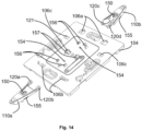
- a clip may also take the form of a pin (second clipping element 121 of the figure 14 ) coming to engage in a hollow (belonging to a first element 120a, 120b of clipping of the figure 14 ).
- the intermediate assembly 110 can be configured to transmit the support force F11, exerted by the first support element 124 on the intermediate assembly 110 when the first support element 124 moves from its stable inactive position to its unstable active position, to the first switch 109 to place it in its active state (i.e., moving from its inactive state to its active state).
- the support force F11 causes the generation of a force (also called support) F111 (schematized in Figure 2 by an arrow) exerted by the intermediate assembly 110 on the first switch 109, resulting in the first switch 103 passing to its active state from its inactive state. Therefore, the intermediate assembly 110 allows a force propagation adapted to activate the first switch 109, especially when the first support zone 103 cannot structurally come into contact with the first switch 109 when the user applies the support force F1 on the first support zone 103.
- the unstable active position of the first support zone 103 and, where applicable, the unstable active position of the first support element 124 are said to be “unstable” because they can only be obtained when the support force F1 is applied since the return device 122 allows an automatic return of the first support zone 103 and, where applicable, of the first support element 124 to their stable inactive position when the support force F1 applied to the first support zone 103 ceases, hence the notion of stability of the stable inactive position for which the control assembly 102 does not allow the first switch 109 to be activated.
- the return device 122 is preferably such that, when no force (in particular force from the user) is applied to the first face 118 of the control assembly 102, it makes it possible to maintain the first support zone 103 in its stable inactive position.
- the control assembly 102 may comprise a second support zone 123 (as shown for example by figures 1, 2 , 8 ) accessible from outside the manual control device 100. Therefore, the electronic control module 101 can comprise the second switch 112 capable of selectively occupying an active state and an inactive state, the second switch 112 being mounted on the circuit 108 printed in particular on its face 116. This allows in particular, in the same vein as what was described above, to interact with a corresponding switch of the electronic control module 101, said switch here being the second switch 112 which the electronic control module 101 comprises.
- the second support zone 123 allows the manual application of a support force F2, by the user of the manual control device 100, causing a movement of the second support zone 123, preferably according to the same degree of freedom as the first support zone 103 (i.e. for example rotation along the pivot axis A1), from a stable inactive position to an unstable active position.
- the return device 122 is further configured to induce a stress tending to push, from its unstable active position, the second support zone 123 towards its stable inactive position.
- the intermediate assembly 110 is further configured to propagate the support force F2 applied to the second support zone 123 towards the second switch 112 so as to act on the state of the second switch.
- the intermediate assembly 110 can exert pressure on the second switch 112 inducing the transition from its inactive state to its active state (or vice versa) or stop exerting pressure on the second switch 112 inducing the transition from its inactive state to its active state (or vice versa).
- control assembly 102 may comprise, on its second face 119, a second support element 125 ( Figure 5 ) associated with the second support zone 123 with which it is integral in movement.
- the role of this second support element 125 is to exert a support force F21 ( Figure 3 ) on the intermediate assembly 110 when the user applies the support force F2 to the second support zone 123.
- the support force F21 exerted on the intermediate assembly 110 causes the generation of a force F211 (shown schematically in Figure 2 by an arrow) exerted by the intermediate assembly 110 on the second switch 112, resulting in the second switch 119 passing to its active state from its inactive state. Therefore, the intermediate assembly 110 allows a force propagation adapted to activate the second switch 112, especially when the second support zone 123 cannot structurally come into contact with the second switch 112 when the user applies the support force F2 to the second support zone 123.
- the second switch 112 in its active state; and in the stable inactive position of the second support zone 123 (associated where appropriate with a stable inactive position of the second support element 125), the second switch 112 is in its inactive state.
- the unstable active position of the second support zone 123 and the unstable active position of the second support element 125 are said to be “unstable” because they can only be obtained when the support force F2 is applied since the return device 122 allows an automatic return of the second support zone 123 and of the second support element 125 to their stable inactive position when the support force F2 on the second support zone 123 ceases, hence the notion of stability of the stable inactive position for which the control assembly 102 does not allow the second switch 112 to be activated.
- a second pin 141 of the intermediate assembly 110 bears on the second switch 112 then in the active state.
- the return device 122 makes it possible to maintain both the first support zone 103 and the second support zone 123 in their stable inactive position.
- the electronic control module 101 is configured to generate the control order forming a signal representative of the user instruction corresponding to lowering or deploying the mobile screen when the second switch 112 changes from its inactive state to its active state.
- the intermediate assembly 110 is associated with the pivot axis A2 allowing it to pivot in its entirety or only in part depending on whether the support force is applied to the first support zone 103 or the second support zone 123.
- the intermediate assembly 110 can be formed in a single piece forming a rocker.
- the intermediate assembly 110 can be formed in two pieces 110a, 110b ( figures 6 And 7 ) which pivot selectively depending on whether the support force is applied to the first support zone 103 or the second support zone 123.
- the intermediate assembly 110 is formed in two parts 110a, 110b
- these two parts 110a, 110b can pivot relative to each other, they can then each comprise at least one of the first clipping elements 120a, 120b, 120c, 120d (for example two in number) clipped onto the second corresponding clipping element 121 formed by a rod.
- the part 110b comprises the rigid part 111 and the part 110a comprises another rigid part 142 having a movement capability independent of the movement capability of the rigid part 111.
- the control assembly 102 may comprise, as illustrated in Figures 1 and 2 , a central support zone 133 actuable by manual application of a support force F3, by the user of the manual control device 100, on the control assembly 102 so as to cause a displacement of the central support zone 133 towards the support 104 from a stable inactive position to an unstable active position inducing the actuation of a third switch 113, belonging to the electronic control module 101, mounted on the printed circuit 108 (in particular on its face 116), the third switch 113 being arranged to be actuated by a portion 134 of the intermediate assembly 110 following a deformation of the intermediate assembly 110 caused by a pressure of the control assembly 102 on the portion 134 of the intermediate assembly 110 induced by the displacement of the central support zone 133.
- the third switch 113 is capable of selectively occupying an active state and an inactive state.
- the aforementioned actuation of the third switch 113 corresponds to its transition from its inactive state to its active state when the central support zone 133 is in its unstable active position.
- the electronic control module 101 is configured to generate the control order forming a signal representative of the user instruction corresponding to stopping the movement of the mobile screen when the third switch 113 passes from its inactive state to its active state, for example in order to maintain the mobile screen in a current configuration of partial obstruction of the opening between the obstruction configuration and the retracted configuration.
- control assembly 102 can exert direct pressure on the third switch 113 to place it in its active state. This is particularly possible when the central support zone 133 is located directly above the printed circuit 108 and particularly directly above the third switch 113.
- the third switch 113 in its inactive state; and in the unstable active position of the central support zone 133, the third switch 113 is in its active state.
- the return device 122 may also be configured to induce a force tending to push, from its unstable active position, the central support zone 133 towards its stable inactive position.
- the return device 122 makes it possible to maintain both the first support zone 103, the central support zone 133, and, where appropriate, the second support zone 123 in their stable inactive position.
- the manual control device 100 is configured so that the support force F3 applied to the central support zone 133 does not interfere with the first switch 109, nor where appropriate the second switch 112, by actuating it or them in an undesired manner.
- the central support zone 133 can be arranged in line with the pivot axis A2 of the intermediate assembly 110.
- control assembly 102 comprises a third support element 143 on its second face 119 to exert a support force F31 on the intermediate assembly 110 when the user applies the support force F3 to the central support zone 133.
- the portion 134 may comprise a third support pin 144 arranged to pass through the support 104, in particular through the third opening 139 arranged between two second clipping elements 121 used to form a pivot connection between the intermediate assembly 110, or each of its two parts 110a, 110b, and the support 104; this makes it possible to avoid activating the first or second switch 109, 112 when the central support zone 133 is stressed via the support force F3.
- the third support pin 144 can exert a support F311 on the third switch 113 when the support force F3 is applied to the central support zone 133.
- the unstable active position of the central support zone 133 and, where appropriate, the unstable active position of the third support element 143 are said to be “unstable” because they can only be obtained when the support force F3 is applied to the central support zone 133 since the return device 122 allows an automatic return of the central support zone 133.
- the intermediate assembly 110 may comprise, as illustrated by way of example in figure 9 , a key 126 having a rigid surface 127 facing the control assembly 102 and capable of receiving, in various parts of the surface of the rigid surface 127 offset from each other and offset relative to a region 145 of said surface directly above an actuating member 128 belonging to the first switch 109, a pressure exerted by the control assembly 102 when the pressure force F1 is applied to the first pressure zone 103, said pressure being adapted to cause a movement of the key 126 to act on the state of the first switch 109 in reaction to said pressure force F1.
- the intermediate assembly 110 can comprise two keys 126, for example independent, each allowing interaction, in particular in the manner described above, respectively with the first switch 109 (key 126 on the right in Figure 9 ) and with the second switch 112 (left key in figure 9 ).
- the degree of freedom of the first support zone 103 can be in figure 9 a translation, which induces, when the support force F1 is applied to the first support zone 103, a force on the key 126 allowing its translation in the direction of the first switch 109 on which it comes to bear in particular via the first pin 140.
- This is also applicable in the context of the second switch 112 and the second support zone 123.
- the key 126 may comprise a first part comprising a first face 126a and a second face 126b opposite the first face 126a of the first part, the first face 126a of said first part delimiting the bearing surface 127.
- the key 126 may comprise a second part formed as a projection from the second face 126b of said first part, said second part adopting the shape of a pin 140 (where appropriate the first pin 140) of which a free end opposite the first part is configured to press on the actuating member 128 of the first switch 109.
- This is of course transposable in the case of the presence of two keys and the second switch 112 in the sense that the free end of the corresponding pin is configured to press on the actuating member 128 of the second switch 109. 112.
- the base 130 may comprise the retaining means 117a, 117b.
- the base 130 extends at least partially between the intermediate assembly 110 and the button 131. In other words, the base 130 is arranged between the intermediate assembly 110 and the button 131.
- the button 131 comprises the first support zone 108 and, where appropriate, one and/or the other of the second support zone 123 and the central support zone 133.
- control assembly 102 comprising the base 130 and the button 131 with the interposition of the elastic ring 132, and particularly adapted to communicate to the user a qualitative sensation of use by limiting or eliminating the functional games of the button 131.
- the control assembly 102 can take the form of a button 131 comprising the first support zone 103, this button 131 being mounted to move relative to the support 104 via the first assembly means 106a, 106c.
- the second embodiment is such that the control assembly 102 does not comprise a base. The control assembly 102 is then less expensive and simpler to produce than in the context of the first embodiment.
- the button 131 for example as present in the second embodiment, may have a peripheral rim 146 extending to the edge of the second face 119 of the control assembly 102 so as to delimit a cavity 147 housing at least in part the intermediate assembly 110.
- the figures 10 to 12 illustrate a manual control device 100 of the On-Off type also called a push button where the control assembly 102 is a button.
- the pressing force F1 can be applied to the first pressing zone 103 so that the second face 119 of the control assembly 102 exerts the pressing force F11 on the intermediate assembly 110 consisting of a part pivotally mounted on the support 104 to press the first switch 109 (not visible) housed in the housing 114 behind the support 104 on the Figure 12 .
- the button returns to a rest configuration in which the first pressure zone 103 is in its stable inactive position thanks to the return device 122.
- the degree of freedom is a rotation around the axis A1 represented in particular in Figure 10 .
- the return device 122 can be integrated into the button 131 and for example be formed by strips 148a, 148b arranged at the end of the rim 146 and for example coming from the same material as this rim 146. These strips are then constantly urged against the support 104 to avoid functional play of the button and ensure the function of return device 122.
- control assembly 102 may comprise a housing 149 and the intermediate assembly 110 may then be at least partly housed in said housing 149.
- housing 149 is included in cavity 147.
- the housing 149 is delimited by a recess in the base 130.
- the intermediate assembly 110 and the control assembly 102 can be linked so that when the first support zone 103 passes from the unstable active position to the stable inactive position, the stress induced by the return device 122 also tends to induce a movement of said at least one rigid part 111 of the intermediate assembly 110 allowing the state of the first switch 109 to pass from the active state to the inactive state when the support force F1 on the first support zone 103 is released.
- This mechanical connection may be a mechanical attachment to cause a solidarity in movement (in this case the return device 122 may cooperate with one or the other of the control assembly 102 and the intermediate assembly 110) or a simple mechanical contact (in this case the return device 122 may cooperate with the intermediate assembly 110 which can then appropriately push back the control assembly 102).
- the electronic control module 101 may comprise the return device 122 arranged on the support 104 and/or formed by the switch(es) (where appropriate, chosen from the first, second and third switches 109, 112, 113) which then each have a deformable cup, in particular a metal one.
- the deformable cup has a spring effect when it is deformed so as to tend to return to its initial shape (the deformable cup is then said to have a shape memory) making it possible to push back the intermediate assembly 110, as well as the control assembly 102 via the intermediate assembly 110.
- the intermediate assembly 110 exerts pressure on the corresponding switch (where appropriate, chosen from the first, second and third switches 109, 112, 113) from which it results that the latter is in the active state due to the positioning of the corresponding zone (where appropriate, chosen from the first support zone 103, the second support zone 123 and the central support zone 133) in its unstable active position.
- the cup(s) can then be part of, or form, the return device 122.
- the manual control device 100 may comprise at least one return member 150 separate from the return device 122 and configured to induce, when the first switch 109 is placed in the active state by pressing the intermediate assembly 110 on the first switch 109, a stress tending to place the intermediate assembly 110 in a configuration such that the first switch 109 is in its inactive state.
- the stress induced by the return member 150 is insufficient to cause a movement of the intermediate assembly 110 positioning it in said configuration such that the first switch 109 is in its inactive state.
- the intermediate assembly 110 may comprise the return member 150, the effect of which may be added to that of the return device 122.
- the role of this return member 150 is to prevent the intermediate assembly 110 from interacting with the switch(es) (i.e., where appropriate, the first to third switches 103, 112, 113), which would result in said switch(es) accidentally switching to their active state without the control assembly 102 having been activated by the user.
- the return member 150 also makes it possible to keep the intermediate assembly 110 and the first support element 124 and/or the second support element 125 in contact, which prevents play or empty movement when the control assembly 102 is activated.
- This return member 150 may take the form of a spring blade which may be compressed when the first switch 109 is active so as to allow the intermediate assembly 110 to return to a rest configuration when the bearing force F1 on the first bearing zone 103 ceases.
- the intermediate assembly 110 may comprise a plurality of return members 150, for example to distribute the forces and/or to also allow the intermediate assembly 110 to return to a rest configuration when the bearing force F2 on the second bearing zone 123 ceases.
- each return member 150 can come from a single piece with a body of the intermediate assembly 110 and be turned towards the support 104 where it can rest or be in contact.
- each return member 150 can be made of a single material with a body of one of the two parts of the intermediate assembly 110 and can be turned towards the support 104 where it can bear or be in contact.
- Each of the first and second parts 110a, 110b comprising at least one of the return members 150 can then be turned towards the support 104 where it can bear or be in contact.
- the return members 150 can be arranged on either side of the pivot axis A2.
- the return organs 150 can adopt a spring blade form.
- the return member(s) 150 may each be formed by an independent element added such as a metal spring strip arranged in a suitable manner, this making it possible to simplify the mechanical design of the intermediate assembly 110.
- the return member 150 can be integrated into the intermediate assembly 110, or can be integrated into the first switch 109, in particular in the case of the presence of the deformable cup sufficient for push back the intermediate assembly.
- the intermediate assembly 110 may comprise, as illustrated in figures 7 clips 152 configured to cooperate with holes 153 of the support 104 in order to limit the pivoting amplitude of the intermediate assembly 110 or of the first and second parts 110a, 110b of the intermediate assembly 110 while participating in the mounting of the intermediate assembly 110 to the support 104 (these holes 153 can then be part of the second assembly means 107).
- THE figures 13 And 14 illustrate an alternative embodiment of the support 104 and of the actuation assembly 110 then formed in two parts 110a, 110b (the first and second parts mentioned above).
- Each of the parts 110a, 110b comprises a return member 150 adopting the form of a blade, one longitudinal end of which is connected to the body of the corresponding part 110a, 110b, while the other longitudinal end is left free in order to bear on the support 104, for example on a projection 154 of the support 104.
- Each part 110a, 110b may comprise one or more shoulders 155 each cooperating with a clip 156 belonging to the support 104 in order to limit the amplitude of pivoting of the parts 110a, 110b of the intermediate assembly 110 while participating in the mounting of the intermediate assembly 110 to the support 104.
- the support 104 comprises two ears 157 (also called projecting parts) each provided with a second clipping element 121, in the form of a truncated cone-shaped pin, onto which the first corresponding clipping element 120a, 120b of the first part 110a can be clipped in order to allow a rotational movement.
- the second part 110b can then be clipped in a similar manner onto the first part 110a in order to allow a rotational movement between the first and second parts 110a, 110b.
- the invention also relates to a kit for forming the manual control device 100 as described.
- the kit comprises the electronic control module 101, the intermediate assembly 110 and a plurality of different control assemblies 102 each capable of being mounted to at least a portion of the first assembly means 106a, 106b, 106c such as for example the control assembly as visible in Figure 5 and the entire control as seen in Figure 11 .
- the manual control device 100 described and the associated kit find an industrial application in the field of home automation, in particular with a view to controlling an actuator.
Landscapes
- Casings For Electric Apparatus (AREA)
- Feedback Control In General (AREA)
Applications Claiming Priority (1)
| Application Number | Priority Date | Filing Date | Title |
|---|---|---|---|
| FR2315030A FR3157576A1 (fr) | 2023-12-22 | 2023-12-22 | Dispositif de commande manuelle |
Publications (1)
| Publication Number | Publication Date |
|---|---|
| EP4576146A1 true EP4576146A1 (de) | 2025-06-25 |
Family
ID=89661132
Family Applications (1)
| Application Number | Title | Priority Date | Filing Date |
|---|---|---|---|
| EP24221282.7A Pending EP4576146A1 (de) | 2023-12-22 | 2024-12-18 | Manuelle steuervorrichtung |
Country Status (2)
| Country | Link |
|---|---|
| EP (1) | EP4576146A1 (de) |
| FR (1) | FR3157576A1 (de) |
Citations (4)
| Publication number | Priority date | Publication date | Assignee | Title |
|---|---|---|---|---|
| EP1037230A2 (de) * | 1999-03-15 | 2000-09-20 | Matsushita Electric Industrial Co., Ltd. | Mehrrichtungsschalter und seine Verwendung |
| US20110259722A1 (en) * | 2010-04-27 | 2011-10-27 | Leviton Manufacturing Co., Inc. | Electrical devices with removable actuator frames |
| EP2439761A2 (de) | 2010-10-11 | 2012-04-11 | EQ-3 Entwicklung GmbH | Elektrisches Installationsgerät |
| DE102021213600A1 (de) * | 2021-12-01 | 2023-06-01 | Robert Bosch Gesellschaft mit beschränkter Haftung | Bedieneinheit, insbesondere zur Anordnung an einem Lenker eines Zweiradfahrzeugs |
-
2023
- 2023-12-22 FR FR2315030A patent/FR3157576A1/fr active Pending
-
2024
- 2024-12-18 EP EP24221282.7A patent/EP4576146A1/de active Pending
Patent Citations (4)
| Publication number | Priority date | Publication date | Assignee | Title |
|---|---|---|---|---|
| EP1037230A2 (de) * | 1999-03-15 | 2000-09-20 | Matsushita Electric Industrial Co., Ltd. | Mehrrichtungsschalter und seine Verwendung |
| US20110259722A1 (en) * | 2010-04-27 | 2011-10-27 | Leviton Manufacturing Co., Inc. | Electrical devices with removable actuator frames |
| EP2439761A2 (de) | 2010-10-11 | 2012-04-11 | EQ-3 Entwicklung GmbH | Elektrisches Installationsgerät |
| DE102021213600A1 (de) * | 2021-12-01 | 2023-06-01 | Robert Bosch Gesellschaft mit beschränkter Haftung | Bedieneinheit, insbesondere zur Anordnung an einem Lenker eines Zweiradfahrzeugs |
Also Published As
| Publication number | Publication date |
|---|---|
| FR3157576A1 (fr) | 2025-06-27 |
Similar Documents
| Publication | Publication Date | Title |
|---|---|---|
| EP3635764B1 (de) | Steuerungsvorrichtung | |
| EP2501882B1 (de) | Schlüssel mit versenkbarem einsatz und mit erhöhter mechanischer festigkeit | |
| FR2916929A1 (fr) | Terminal portatif | |
| EP1437260B1 (de) | Auf zwei Achsen rotierbarer Fahrzeugaussenrückspiegel | |
| EP2331777A1 (de) | Schlüssel mit klappeinsatz und entsprechendes ausziehmodul | |
| EP3333870B1 (de) | Elektrischer schalter | |
| EP4576146A1 (de) | Manuelle steuervorrichtung | |
| WO2025133535A1 (fr) | Dispositif de commande de manuelle | |
| EP2978006B1 (de) | Elektrischer schalter | |
| EP4576147A1 (de) | Manuelle steuervorrichtung | |
| FR3089658A1 (fr) | Dispositif de commande d’un appareil électronique, procédés de réglage du dispositif et rétroviseur de véhicule automobile intégrant un tel dispositif. | |
| EP1795642B1 (de) | Bedientableau für elektrisches Haushaltsgerät | |
| WO2002071129A1 (fr) | Paire de lunettes a mecanisme d'ouverture automatique de branche | |
| EP4576148A1 (de) | Manuelle steuereinrichtung mit federbelastetem taster | |
| EP4388569B1 (de) | Handbediengerät mit einem torusförmigen element zur rückführung des bedienknopfes | |
| FR3107295A1 (fr) | Dispositif de verrouillage pour une pièce mobile d’un véhicule | |
| EP1376772A1 (de) | Elektrischer Steckanschluss mit Verschlussbuchsenblenden und Baureihe mit einem solchen Steckanschluss | |
| EP3685234B1 (de) | Steuervorrichtung mindestens einer elektronischen funktion eines tragbaren geräts | |
| EP1895078A1 (de) | Einklappbare Schlüsselvorrichtung und Montageverfahren | |
| EP4604153A1 (de) | Steuervorrichtung zur steuerung einer heimautomatisierungsausrüstung | |
| EP2442337B1 (de) | Schlüsselkontaktvorrichtung | |
| EP3070729B1 (de) | Abschlusseinheit und elektrischer schalter, der eine solche abschlusseinheit umfasst | |
| FR3119265A1 (fr) | Dispositif de commande electromecanique a bouton rotatif | |
| EP1333459A1 (de) | Doppelhubschalter | |
| FR3098359A1 (fr) | Dispositif modulaire mural |
Legal Events
| Date | Code | Title | Description |
|---|---|---|---|
| PUAI | Public reference made under article 153(3) epc to a published international application that has entered the european phase |
Free format text: ORIGINAL CODE: 0009012 |
|
| STAA | Information on the status of an ep patent application or granted ep patent |
Free format text: STATUS: THE APPLICATION HAS BEEN PUBLISHED |
|
| AK | Designated contracting states |
Kind code of ref document: A1 Designated state(s): AL AT BE BG CH CY CZ DE DK EE ES FI FR GB GR HR HU IE IS IT LI LT LU LV MC ME MK MT NL NO PL PT RO RS SE SI SK SM TR |
|
| STAA | Information on the status of an ep patent application or granted ep patent |
Free format text: STATUS: REQUEST FOR EXAMINATION WAS MADE |
|
| 17P | Request for examination filed |
Effective date: 20251117 |
|
| GRAP | Despatch of communication of intention to grant a patent |
Free format text: ORIGINAL CODE: EPIDOSNIGR1 |
|
| STAA | Information on the status of an ep patent application or granted ep patent |
Free format text: STATUS: GRANT OF PATENT IS INTENDED |
|
| INTG | Intention to grant announced |
Effective date: 20260311 |