EP4576154A1 - Quellenmodul und optische vorrichtung für geladene teilchen - Google Patents
Quellenmodul und optische vorrichtung für geladene teilchen Download PDFInfo
- Publication number
- EP4576154A1 EP4576154A1 EP23217561.2A EP23217561A EP4576154A1 EP 4576154 A1 EP4576154 A1 EP 4576154A1 EP 23217561 A EP23217561 A EP 23217561A EP 4576154 A1 EP4576154 A1 EP 4576154A1
- Authority
- EP
- European Patent Office
- Prior art keywords
- actuatable
- charged particle
- optical
- electron
- source
- Prior art date
- Legal status (The legal status is an assumption and is not a legal conclusion. Google has not performed a legal analysis and makes no representation as to the accuracy of the status listed.)
- Pending
Links
Images




Classifications
-
- H—ELECTRICITY
- H01—ELECTRIC ELEMENTS
- H01J—ELECTRIC DISCHARGE TUBES OR DISCHARGE LAMPS
- H01J37/00—Discharge tubes with provision for introducing objects or material to be exposed to the discharge, e.g. for the purpose of examination or processing thereof
- H01J37/02—Details
- H01J37/023—Means for mechanically adjusting components not otherwise provided for
-
- H—ELECTRICITY
- H01—ELECTRIC ELEMENTS
- H01J—ELECTRIC DISCHARGE TUBES OR DISCHARGE LAMPS
- H01J37/00—Discharge tubes with provision for introducing objects or material to be exposed to the discharge, e.g. for the purpose of examination or processing thereof
- H01J37/02—Details
- H01J37/04—Arrangements of electrodes and associated parts for generating or controlling the discharge, e.g. electron-optical arrangement or ion-optical arrangement
- H01J37/10—Lenses
- H01J37/14—Lenses magnetic
-
- H—ELECTRICITY
- H01—ELECTRIC ELEMENTS
- H01J—ELECTRIC DISCHARGE TUBES OR DISCHARGE LAMPS
- H01J2237/00—Discharge tubes exposing object to beam, e.g. for analysis treatment, etching, imaging
- H01J2237/02—Details
- H01J2237/024—Moving components not otherwise provided for
-
- H—ELECTRICITY
- H01—ELECTRIC ELEMENTS
- H01J—ELECTRIC DISCHARGE TUBES OR DISCHARGE LAMPS
- H01J37/00—Discharge tubes with provision for introducing objects or material to be exposed to the discharge, e.g. for the purpose of examination or processing thereof
- H01J37/26—Electron or ion microscopes; Electron or ion diffraction tubes
- H01J37/28—Electron or ion microscopes; Electron or ion diffraction tubes with scanning beams
Definitions
- the present disclosure relates to a source module, a charged particle-optical device, a charged particle-optical apparatus and a method for alignment for a charged particle-optical device.
- Assessment tools which herein are referred to as assessment systems, are known that use a charged particle beam to assess objects, which may be referred to as samples, for example to detect pattern defects.
- These systems typically use electron microscopy techniques, such as a scanning electron microscope (SEM).
- SEM scanning electron microscope
- a primary electron beam of electrons at a relatively high energy is targeted with a final deceleration step to land on a sample at a relatively low landing energy.
- the beam of electrons is focused as a probing spot on the sample.
- the interactions between the material structure at the probing spot and the landing electrons from the beam of electrons cause signal electrons to be emitted from the surface, such as secondary electrons, backscattered electrons or Auger electrons.
- the signal electrons may be emitted from the material structure of the sample.
- a pattern assessment system such as a pattern inspection system
- a module for a charged particle-optical device configured to direct one or more primary beams of charged particles toward a sample location along a beam path
- the module comprising: a wall for a vacuum chamber; and an actuatable charged particle-optical element configured to operate on charged particles directed along the beam path towards the sample location; wherein the actuatable charged particle-optical element is configured to be located outside the wall for the vacuum chamber and to be actuatable relative to the beam path desirably in a direction across the primary beam and/or about an axis across the primary beam.
- a method for a charged particle-optical device configured to direct one or more primary beams of charged particles toward a sample along a beam path, the method comprising: directing charged particles along the beam path toward a sample; operating on the charged particles with an actuatable charged particle-optical element located outside a wall of the charged particle-optical device, the wall being for a vacuum chamber; and actuating the actuatable charged particle-optical element relative to the beam path.
- a method for aligning a plurality of primary beams within a charged particle-optical device for directing the plurality of primary beams along a beam path towards a sample location, the primary beams derived from a source beam generated by a source comprising: directing charged particles in a source beam from a source towards a sample location; deriving a plurality of primary beams from the charged particles of the source beam; measuring an offset of the primary beams relative to a reference; and controlling an actuatable arrangement of the charged particle-optical device using the offset to align the primary beams with the reference, the controlling comprising actuating the actuatable arrangement to move a first component of the actuatable arrangement relative to the source and/or the reference.
- the image acquirer may receive the detection signal from the detector 240, may process the data comprised in the signal as a dataset.
- the image acquirer may construct an image therefrom.
- the image acquirer may thus datasets of the sample optionally in the form of images of sample 208.
- the image acquirer may also perform various post-processing functions, such as generating contours, superimposing indicators on an acquired image, and the like.
- the image acquirer may be configured to perform adjustments of brightness and contrast, etc. of acquired images.
- the storage may be a storage medium such as a hard disk, flash drive, cloud storage, random access memory (RAM), other types of computer readable memory, and the like.
- the storage may be coupled with the image acquirer and may be used for saving scanned raw image data as original images, and post-processed images.
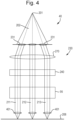
- FIG. 4 schematically depicts a further example of an electron-optical device 230.
- the source 201, the macro collimator 270, the objective lens array 401 and the sample 208 may be as described above, except so far as described differently herein.
- the actuatable electron-optical element comprises the macro collimator 270.
- the macro collimator 270 is taken to be an actuatable electron-optical element for example a magnetic electron-optical element.
- a different electron-optical element may be an actuatable element-optical element.
- the actuatable electron-optical element is configured to operate on the electrons.
- the macro collimator 270 may be configured to operate on the electrons as described elsewhere in this document.
- the electrons may be directed along a beam path towards the sample 208 e.g. as an electron beam such as the source beam 202 and primary beams derived from the source beam 202.
- the beam path may correspond to an electron-optical axis of the electrons directed towards the sample 208.
- the beam path may be a system beam path between the source 201 and the sample 208 for example incorporating the beam path of the source beam and the beam path of the beam grid of the primary beams 211, 212, 213.
- the directing of the source beam may comprise lensing the source beam and/or primary beams by electron-optical components along the system beam path.
- the directing may comprise operating on the source beam along the beam path of the source beam for example to collimate the source beam.
- the directing may comprise lensing the primary beams along the beam path of the primary beams by operating electron-optical elements such as focusing of respective primary beams by the objective lenses of an electron-optical assembly (such as the objective lens assembly).
- the description may focus on the implementation in which the actuatable macro collimator 270 is actuatable in a direction across the beam path. This is translational motion of the actuatable macro collimator 270. However, it will be understood that actuation about an axis across the beam path is also possible. Actuation about an axis across the beam path is a tilting motion of the actuator macro collimator 270. Therefore reference to actuation of the actuatable macro collimator 270 in a direction across the beam path is considered to encompass actuation about an axis across the beam path, unless stated to the contrary.
- the actuatable arrangement is controlled so as to actuate the actuatable arrangement to move a first component of the actuatable arrangement relative to the source 201 and/or the reference plane.
- the first component may comprise the electron-optical element, e.g. the actuatable macro collimator 270.
- the actuatable arrangement is controlled so as to cause the first component to operate on the electrons along the system beam path.
- the operation of the first component may deflect the electrons for example through a first angle for example relative to the reference plane.
- the actuatable macro collimator 270 may be located a collimator distance 72 from the source 201.
- the collimator distance 72 may correspond to the focal length of the macro collimator 270.
- the macro deflector 265 is located a deflector distance 73 from the source 201.
- the difference between the deflector distance 73 and the collimator distance 72 is the distance between the macro collimator 270 and the macro deflector 265, or actuating distance 266. Across this actuating distance 266, the source beam 202 is angled.
- the source beam 202 is not perpendicular to a reference plane of the objective lens assembly 63 for the actuating distance along the beam path, for example the length of the beam path downbeam of the macro collimator 270 and upbeam of the macro deflector 265.
- the angled path of the source beam of the actuating distance allows for compensation of the offset 75.
- the macro deflector 265 operates on the beam path, for example deflector distance (i.e. at the down beam end of the actuating distance), to be substantially perpendicular to the reference plane 272 of the objective lens assembly 63.
- FIG. 7 is a schematic diagram of an actuatable electron-optical element.
- FIG. 7 shows an example in which the actuatable electron-optical element is a macro collimator 270.
- FIG. 7 helps to illustrate actuation of the actuatable macro collimator 270.
- Such an actuatable electron-optical element may comprise an actuating assembly for actuating the actuatable electron-optical element.
- the first actuator and second actuator may be controlled to achieve actuation in the first direction, the second direction or a combination of components in the first and second direction. Movement of the electron-optical element in a first direction, may be achieved by actuating the first actuator and maintaining the position of the second actuator. The control of the second actuator may ensure that the actuatable electron-optical element moves only in the first direction. Movement of the electron-optical element in the second direction, may be achieved by actuating the first actuator and maintaining the position of the first actuator. The control of the first actuator may ensure that the actuatable electron-optical element moves only in the first direction.
- FIG. 7 is a plan view of the actuatable macro collimator 270. In the orientation shown in FIG. 7 , the plane of the paper may contain the direction across the beam path.
- the source module 61 (for example as part of the actuating arrangement) comprises one or more bearings 86 for the respective one or more actuators 80.
- the bearing 86 may be configured to allow for movements perpendicular to the drive direction of the actuator 80.
- the actuator 80 shown at the top of the drawing has a drive direction in the left-right direction.
- the bearing 86 associated with the actuator 80 may allow for the actuatable macro collimator 270 to move perpendicular to the left-right direction.
- the bearing 86 shown at the top of the drawing may allow for that direction of movement.
- FIG. 7 the actuator 80 shown at the top of the drawing has a drive direction in the left-right direction.
- a plurality of actuators 80 are provided.
- the actuators 80 may have orthogonal drive directions (for example for the first actuator and the second actuator respectively the first direction and the second direction).
- the drive directions of the actuators 80 may be different from each other but not orthogonal.
- the drive directions may be oblique to each other.
- the actuatable macro collimator 270 comprises one or more extensions 82 (for example as part of the actuating arrangement) corresponding to the one or more actuators 80.
- Each extension 82 may be referred to as a protrusion.
- the extension 82 is configured to protrude in a radial direction away from a centre of the actuatable macro collimator 270.
- the extension 82 comprises a surface configured to receive the force from the actuator 80. Interaction between the extension 82 and the respective actuator 80 may influence the movement of the actuatable macro collimator. Actuation of the actuator 80 may cause actuation of the actuatable macro collimator 270 via the extension 82.
- the other of the actuators may control movement such as maintain the position of the actuatable macro collimator in the second direction, for example by control of the second actuator and the interaction between the second actuator and the corresponding extension.
- the source module 61 comprises a source module body.
- the source 201 is secured to the source module body.
- the source module body is configured to have a positional relationship with respect to the beam path.
- the source module body may comprise a frame for the source module 61.
- the actuatable macro collimator 270 is mounted relative to the source module body.
- the macro collimator 270 may be mounted relative to the source module so as to allow for actuation of the actuatable macro collimator 270.
- the actuatable macro collimator 270 may be mechanically connected to the source module body in such a way as to allow for freedom of movement of the macro collimator 270 translationally across the beam path and/or tilting about axes across the beam path.
- the extensions 82 are configured to protrude radially beyond a panel (or an outer wall) of the source module body.
- the actuators 80 are located outside of the vacuum chamber (for example as defined by the wall of the vacuum chamber), and optionally outside of the source module body for example the panels of the source module body.
- a part of the actuating arrangement may be located between the wall of the vacuum chamber and the panel of the source module body.
- a part of the actuating arrangement may be outside of both the vacuum chamber and the panel of the source module body.
- a part of the actuating arrangement may extend through panel of the source module body, for example through an aperture defined in the panel.
- a part of the wall and the panel may be the same feature.
- a part of the panel may separate from and outside of a part of the wall.
- the actuators 80 may be located in a region that is under ambient conditions within the charged particle apparatus 40, for example outside the vacuum chamber, during use of the electron-optical apparatus 40.
- ambient conditions may be the ambient conditions within the location in which the electron-optical apparatus is situated which may be atmospheric conditions.
- the actuator determines the position of the collimator for example by determining the position of the respective extension 82.
- the biasing member 81 is intended to ensure that collimator stays in contact with the actuator for example via the respective extension 81.
- the collimator may consequently follow the actuation of the actuator 80.
- the biasing member 81 for the first actuator may be considered to apply a counter force to the respective extension 82 in a direction opposing the first direction in which the first actuator operates, the counter force ensures that the first actuator is maintained in contact (for example via the point of contact of the ball bearing 86) with a surface of the respective extension 82. Note that this arrangement has high stiffness in the drive direction, (e.g.
- the controller 50 is configured to control a drive force of the actuator 80 (so as to control movement of the actuatable macro collimator 270 for example via actuation of the first actuator in the first direction.
- the biasing members are resilient members such springs, for example coil springs.
- the biasing members 81 may be any other type of suitable resilient member such as a leaf spring or may comprise an elastic material such as rubber.
- an opposing actuator may be provided to oppose the actuator 80.
- the actuators 80 may be configured to drive the extension 82 in two opposite directions.
- the top actuator 80 of FIG. 7 may be configured to drive from right to left or from left to right for example to extend or retract in the first direction, as controlled by the controller 50.
- the biasing member 81 may be configured to have a pre-tension to keep the extension 82 in contact with the bearing 86 corresponding to the actuator 80.
- the actuatable macro collimator 270 is provided with an associated restriction plate 83.
- the restriction plate 83 is configured to restrict movement of the actuatable macro collimator 270 in one or more degrees of freedom.
- the restriction plate 83 comprises an inner part 84 and an outer part 85.
- the inner part 84 is connected to the outer part 85 via a connection that is compliant for movement in one direction (a first direction) and restrict movement in another direction (a second direction) for example across the beam path.
- the directions are different.
- the directions may be orthogonal directions with respect to each other. For example in the arrangement shown in FIG.
- connection between the inner part 84 and the outer part 85 comprises longitudinal segments such that the inner part 84 may move relative to the outer part 85 in the left-right directions in the page of the figure, for example the first direction, but may restrict movement in the up-down directions in the page of the figure, for example the second direction.
- the outer part 85 may be connected to the periphery of the restriction plate 83 via a connection that is compliant in one direction for example in a second direction and that restricts movement within the inner part 84 in another direction for example the first direction such as in a direction along the X axis.
- the outer part 85 is shown as being connected to the periphery of the restriction plate 83 by longitudinal segments that make the outer part 85 compliant to movement of the outer part 85 relative to the periphery in the up-down direction in the page of the figure, for example the second direction such as in a direction along the Y axis but to restrict movement within the outer part 85 in the left-right direction in the page of the figure, for example the second direction.
- the inner part 84 and the outer part 85 restrict transmission of the actuation of the actuators 80 in respective directions
- the inner part 84 may move with respect to a periphery of the outer part 85 in the second direction.
- the outer part may move in the first direction.
- the restrictions to movement of the inner part 84 and the outer part 85 may restrict or prevent rotational movement for example about the beam path (e.g. about Rz) between the periphery of the outer part 84 and the inner periphery of the inner part 85.
- Actuation through the restriction plate may be limited to actuation in two degrees of freedom such as in the first direction and in the second direction e.g. along the X and Y axes. Actuation about the beam path e.g. around the Z axes is restricted if not prevented.
- the inner part 84 of the restriction plate 83 is secured to the actuatable macro collimator 270.
- the inner part 84 may be connected to the macro collimator 270 for example a coil of the macro collimator.
- the restriction plate 83 By providing the restriction plate 83, the movement of the actuatable macro collimator 270 may be restricted to movement along the actuating directions (i.e. the left-right directions and the up-down directions) for example in different directions across the beam path, such as in the X and Y axes.
- the restriction plate 83 may restrict if not prevent rotation of the actuatable macro collimator 270 about an axis along the beam path, such around the z axis.
- the periphery of the restriction plate 83 is mounted relative to the actuatable macro collimator 270.
- one or more struts may be provided to connect the periphery of the actuatable macro collimator 270 to the periphery of the restriction plate 83.
- FIG. 8 is a schematic diagram of a different arrangement for the actuatable macro collimator 270 that has one or more differences relative to the arrangement shown in and described with reference to FIG. 7.
- FIG. 8 shows an actuating arrangement that is different from the actuating arrangement shown in and described with reference to FIG. 7 .
- three actuators 80 are provided (for example as part of the actuating arrangement) for actuating the actuatable macro collimator 270.
- the actuators 80 are provided for translationally moving the actuatable macro collimator 270 in two degrees of freedom across the beam path for example in two different directions which may correspond to the x and y axes.
- the controller 50 may be configured to control the actuators 80 so as to substantially prevent rotational movement of the actuatable macro collimator 270.
- three actuators 80 are provided for actuating the actuatable macro collimator 270 in two degrees of freedom for example two different directions across the beam path such as in the X and Y axes.
- the additional actuator 80 may be used to restrict rotation of the actuatable macro collimator 270.
- the additional actuator 80 may avoid the need to use the restriction plate 83.
- the restriction plate 83 shown in FIG. 7 may be omitted.
- a first actuator may operate in a first direction through contact with a resiliently biased extension 82, such as across the page of FIG. 8 .
- a second actuator and third actuators may also operate respectively in a second direction and a third direction through contact with a respective resiliently biased extension 82.
- the second direction and the third direction may be parallel and oppose each other, for example in a direction of the length of the page of FIG. 8 . Operation of the first actuator whilst maintaining the positions of the second actuator and the third actuator may causes movement of the actuatable electron-optical element in the first direction.
- Simultaneous operation of the second actuator and the third actuator to move in a common direction (so the second actuator may retract in the second direction and the third actuator may extend in the third direction) whilst maintaining the position of the first actuator may cause movement of the actuatable electron-optical element in a direction orthogonal to the first direction.
- This operation of the actuating assembly shown and depicted in FIG.8 is exemplary.
- a different control arrangement may be used for other embodiments of the actuating arrangement for example in which the actuators are located at different azimuthal positions from that depicted.
- Such other actuating arrangements may achieve the same nature of actuation of the actuatable electron-optical element, for example in different directions (e.g. in the x and y axes) across the beam path without rotational displacement of the electron-optical element.
- FIG. 9 is a schematic diagram showing a side-on view of the actuatable macro collimator 270 of FIG. 8 .
- FIG. 9 helps to show how the actuatable macro collimator 270 engages with the source module body 90 of the source module 61.
- the representation may also assist in relating the actuatable macro collimator 270 and the actuating assembly to the vacuum chamber, or at least a wall 94 of the vacuum chamber.
- the actuatable macro collimator 270 (for example the actuating assembly) comprises one or more collimator supports 93.
- the actuatable macro collimator 270 comprises two, three or more than three collimator supports 93.
- the collimator supports 93 may be, for example, pads.
- the collimator supports 93 may be provided at a downbeam side, such as an underside, of the actuatable macro collimator 270.
- the collimator supports 93 are provided to make contact with the source module body 90.
- the actuatable macro collimator 270 may be configured to be supported by the collimator supports 93, for example to rest or hang on the collimator supports 93.
- the collimator supports may provide a connection between the actuatable macro collimator 270 and the source module body with high stiffness.
- the connection provided by the collimator supports 93 may enable movement of the actuatable macro collimator 270 in the directions in which the actuatable macro collimator 270 is actuated.
- the source module 61 (for example the actuating assembly) comprises one or more resilient members 91.
- the resilient members 91 may be, for example, springs or may comprise a elastic material such as rubber.
- the resilient members 91 are configured to apply a force between the source module body 90 and the actuatable macro collimator 270.
- the resilient members 91 may be configured to support the mass, such as take part of the weight of, the actuatable macro collimator 270.
- the actuatable macro collimator 270 is mounted on the source module body 90 so as to allow for movement during actuation of the actuatable macro collimator 270.
- the collimator supports 93 may have a sliding contact with a surface of the source module body 90.
- there is relatively low friction between the collimator supports 93 and the source module body 90 so as to avoid interfering undesirably with actuation of the actuatable macro collimator 270.
- the resilient members 91 are configured to reduce the friction force between the actuatable macro collimator 270 and the source module body 90.
- the source module body 90 such as panel 97 of the source module body 90, comprises one or more openings 92.
- the extensions 82 are configured to protrude through the openings 92 of the source module body 90, for example in the panel 97.
- modules and a modular assembly comprising at least two adjacent modules may comprise part of an optical or electron optical system or another other system for fabricating a patterned product such as a semiconducting component such as a chip.
- Such systems may comprise at least one of a lithographic system such as an electron or photon lithographic systems, an assessment system such as a metrology or inspection system or a system for use in track such as a coater, developer or other processing system.
- a module for a charged particle-optical device configured to direct one or more primary beams of charged particles toward a sample location along a beam path
- the module comprising: a wall for a vacuum chamber; and an actuatable charged particle-optical element configured to operate on charged particles directed along the beam path towards the sample location; wherein the actuatable charged particle-optical element is configured to be located outside the wall for the vacuum chamber and to be actuatable relative to the beam path desirably in a direction across the primary beam and/or about an axis across the primary beam.
- Clause 8 The module of any preceding clause, comprising: a charged particle-optical deflector configured to deflect the charged particles.
- Clause 10 The module of clause 8 or 9, wherein the charged particle-optical deflector is downbeam of the actuatable charged particle-optical element.
- Clause 15 The module of clause 14, wherein the directions of the respective degrees of freedom are angled with respect to each other.
- Clause 18 The module of clause 17, wherein the respective axes are angled with respect to each other.
- Clause 19 The module of any preceding clause, comprising: a module body configured to have a positional relationship with respect to the beam path.
- Clause 20 The module of clause 19, wherein the source module body is configured to support the actuatable charged particle-optical element, compliant to the actuation of the actuatable charged particle-optical element relative to the beam path.
- Clause 22 The module of clause 21, wherein the lens comprises a condenser lens and/or a collimator lens.
- a charged particle-optical device configured to direct a plurality of primary beams of charged particles toward a sample location, the charged particle-optical device comprising: the module of any preceding clause.
- Clause 29 The charged particle-optical device of clause 28, wherein the plurality of primary beams derive from the source beam.
- Clause 30 The charged particle-optical device of clause 28 or 29, comprising: a charged particle-optical assembly configured to direct one or more primary beams of charged particles derived from the source beam toward the sample location.
- Clause 31 The charged particle-optical device of clause 30, wherein the actuatable charged particle-optical element is configured to be actuatable relative to the charged particle-optical assembly in a direction across the source beam and/or about an axis across the source beam.
- Clause 32 The charged particle-optical device of clause 30 or 31, wherein the charged particle-optical assembly is configured, in use, to operate under vacuum.
- Clause 33 The charged particle-optical device of any of clauses 30-32, comprising: a vacuum chamber for the charged particle-optical assembly.
- Clause 35 The charged particle-optical device of any of clauses 30-34, wherein the source is secured to the charged particle-optical assembly.
- Clause 36 The charged particle-optical device of clause 35, wherein the source is secured to the charged particle-optical assembly via a frame.
- Clause 37 The charged particle-optical device of any of clauses 30-36, wherein the actuatable charged particle-optical element is located upbeam of the charged particle-optical assembly.
- Clause 38 The charged particle-optical device of any of clauses 30-37, wherein the charged particle-optical assembly comprises objective lenses configured to focus the respective one ore more beams onto the sample location.
- Clause 39 The charged particle-optical device of any of clauses 27-38, comprising: a vacuum chamber at least partly defined by the wall.
- a charged particle-optical apparatus comprising: the charged particle-optical device of any of clauses 27-39.
- Clause 41 The charged particle-optical apparatus of clause 40, comprising: an actuatable stage configured to support a sample.
- a method for a charged particle-optical device configured to direct one or more primary beams of charged particles toward a sample along a beam path, the method comprising: directing charged particles along the beam path toward a sample; operating on the charged particles with an actuatable charged particle-optical element located outside a wall of the charged particle-optical device, the wall being for a vacuum chamber; and actuating the actuatable charged particle-optical element relative to the beam path.
- Clause 43 The method of clause 42, wherein the actuatable charged particle-optical element is actuated while a volume within the wall of the vacuum chamber is maintained at a vacuum pressure.
- Clause 45 The method of clause 44, comprising: securing a source, configured to generate a source beam from which the primary beams are derived, to the charged particle-optical assembly.
- Clause 46 The method of clause 45, wherein the source is secured to the charged particle-optical assembly before the actuatable charged particle-optical element is actuated.
- Clause 48 The method of any of clauses 42-47, wherein the actuating of the charged particle-optical element causes a difference in the operating of the actuatable charged particle-optical element along the beam path.
- a method for aligning a plurality of primary beams within a charged particle-optical device for directing the plurality of primary beams along a beam path towards a sample location, the primary beams derived from a source beam generated by a source comprising: directing charged particles in a source beam from a source towards a sample location; deriving a plurality of primary beams from the charged particles of the source beam; measuring an offset of the primary beams relative to a reference; and controlling an actuatable arrangement of the charged particle-optical device using the offset to align the primary beams with the reference, the controlling comprising actuating the actuatable arrangement to move a first component of the actuatable arrangement relative to the source and/or the reference.
- Clause 50 The method of clause 49, wherein the reference is of a charged particle-optical assembly of the charged particle-optical device, wherein the charged particle-optical assembly is for operating on the primary beams.
- Clause 51 The method of clause 50, wherein the reference is a reference plane of the charged particle-optical assembly.
- Clause 54 The method of any of clauses 49-53, wherein the actuating of the first component is outside a vacuum chamber comprising the beam path and the charged particle-optical assembly.
- Clause 55 The method of any of clauses 49-54, comprising: operating on the charged particles by the actuatable arrangement upbeam of where the plurality of beams are derived from the charged particles of the source beam.
- Clause 56 The method of any of clauses 49-54, comprising: operating on the charged particles by the actuatable arrangement downbeam of where the plurality of beams are derived from the charged particles of the source beam.
- Clause 57 The method of any of clauses 49-56, wherein the actuatable arrangement comprises the first component and a second component, wherein the first component and the second component are positioned along the beam path and distanced from each other.
- Clause 60 The method of any of clauses 57-59, wherein the second component comprises a deflector configured to deflect the charged particles along the beam path.
- Clause 61 The method of clause 60, wherein the deflecting is performed at a location along the beam path distanced from the first component.
- Clause 62 The method of any of clauses 49-62, wherein the controlling comprises cooperating control of the first and second components comprising deflecting respective angles in the beam path of the charged particles from the source with respect to the reference for aligning the source relative to the reference.
- Clause 64 The method of any of clauses 49-63, wherein the first component comprises an actuatable charged particle-optical element.
- Clause 65 The method of any of clauses 49-64, wherein the deriving is performed at a charged particle-optical assembly for operating on the primary beams.
- Clause 66 The method of any of clauses 49-65, wherein the directing comprises lensing the primary beams.
- Clause 67 The method of clause 66, wherein the directing comprises lensing the primary beams by operating objective lenses of a charged particle-optical assembly on respective primary beams.
- Clause 68 The method of any of clauses 49-67, wherein the measuring comprises detecting the primary beams.
- Reference to a component or system of components or elements being controllable to manipulate a charged particle beam in a certain manner includes configuring a controller or control system or control unit to control the component to manipulate the charged particle beam in the manner described, as well as optionally using other controllers or devices (e.g. voltage supplies and/or current supplies) to control the component to manipulate the charged particle beam in this manner.
- a voltage supply may be electrically connected to one or more components to apply potentials to the components, such as in a non-limited list including the control lens array 250 and the objective lens array 241.
- references to upper and lower, up and down, above and below, etc. should be understood as referring to directions parallel to the (typically but not always vertical) upbeam and downbeam directions of charged particle beams impinging on the sample 208.
- references to upbeam and downbeam are intended to refer to directions in respect of the beam path independently of any present gravitational field.
- Electron-optics described herein may take the form of a series of aperture arrays or electron-optical elements arranged in arrays along a beam or a multi-beam path. Such electron-optical elements may be electrostatic. In an embodiment all the electron-optical elements, for example from a beam limiting aperture array to a last electron-optical element in a beam path before a sample, may be electrostatic and/or may be in the form of an aperture array or a plate array. In some arrangements one or more of the electron-optical elements are manufactured as a microelectromechanical system (MEMS) (i.e. using MEMS manufacturing techniques). Electron-optical elements may have magnetic elements and electrostatic elements.
- MEMS microelectromechanical system
- a compound array lens may feature a macro magnetic lens encompassing the multi-beam path with an upper and lower pole plate within the magnetic lens and arranged along the multi-beam path.
- the pole plates may be an array of apertures for the beam paths of the multi-beam. Electrodes may be present above, below or between the pole plates to control and optimize the electromagnetic field of the compound lens array.
- An assessment apparatus, tool or system may comprise apparatus which makes a qualitative assessment of a sample (e.g. pass/fail), one which makes a quantitative measurement (e.g. the size of a feature) of a sample or one which generates an image of map of a sample.
- assessments apparatus, tools or systems are inspection tools (e.g. for identifying defects), review tools (e.g. for classifying defects) and metrology tools, or tools capable of performing any combination of assessment functionalities associated with inspection tools, review tools, or metrology tools (e.g. metro-inspection tools).
- controller or control system or control unit may be computer-implemented. Any suitable combination of elements may be used to provide the required functionality, including for example CPUs, RAM, SSDs, motherboards, network connections, firmware, software, and/or other elements known in the art that allow the required computing operations to be performed.
- the required computing operations may be defined by one or more computer programs.
- the one or more computer programs may be provided in the form of media, optionally non-transitory media, storing computer readable instructions. When the computer readable instructions are read by the computer, the computer performs the required method steps.
- the computer may consist of a self-contained unit or a distributed computing system having plural different computers connected to each other via a network.
Landscapes
- Chemical & Material Sciences (AREA)
- Analytical Chemistry (AREA)
- Analysing Materials By The Use Of Radiation (AREA)
Priority Applications (3)
| Application Number | Priority Date | Filing Date | Title |
|---|---|---|---|
| EP23217561.2A EP4576154A1 (de) | 2023-12-18 | 2023-12-18 | Quellenmodul und optische vorrichtung für geladene teilchen |
| PCT/EP2024/082324 WO2025131453A1 (en) | 2023-12-18 | 2024-11-14 | Module and charged particle-optical device |
| TW113148026A TW202534417A (zh) | 2023-12-18 | 2024-12-11 | 模組及帶電粒子光學裝置 |
Applications Claiming Priority (1)
| Application Number | Priority Date | Filing Date | Title |
|---|---|---|---|
| EP23217561.2A EP4576154A1 (de) | 2023-12-18 | 2023-12-18 | Quellenmodul und optische vorrichtung für geladene teilchen |
Publications (1)
| Publication Number | Publication Date |
|---|---|
| EP4576154A1 true EP4576154A1 (de) | 2025-06-25 |
Family
ID=89223688
Family Applications (1)
| Application Number | Title | Priority Date | Filing Date |
|---|---|---|---|
| EP23217561.2A Pending EP4576154A1 (de) | 2023-12-18 | 2023-12-18 | Quellenmodul und optische vorrichtung für geladene teilchen |
Country Status (1)
| Country | Link |
|---|---|
| EP (1) | EP4576154A1 (de) |
Citations (4)
| Publication number | Priority date | Publication date | Assignee | Title |
|---|---|---|---|---|
| JPH07335158A (ja) * | 1994-06-14 | 1995-12-22 | Shimadzu Corp | 電子線光軸合わせ装置 |
| EP1602121A2 (de) | 2003-03-10 | 2005-12-07 | Mapper Lithography Ip B.V. | Vorrichtung zur erzeugung einer vielzahl von teilstrahlen |
| US20120145899A1 (en) * | 2010-12-09 | 2012-06-14 | Honda Motor Co., Ltd | Scanning electron microscope |
| EP4002421A1 (de) | 2020-11-12 | 2022-05-25 | ASML Netherlands B.V. | Objektivlinsengruppenanordnung, elektronenoptisches system, elektronenoptisches systemarray, verfahren zur fokussierung |
-
2023
- 2023-12-18 EP EP23217561.2A patent/EP4576154A1/de active Pending
Patent Citations (4)
| Publication number | Priority date | Publication date | Assignee | Title |
|---|---|---|---|---|
| JPH07335158A (ja) * | 1994-06-14 | 1995-12-22 | Shimadzu Corp | 電子線光軸合わせ装置 |
| EP1602121A2 (de) | 2003-03-10 | 2005-12-07 | Mapper Lithography Ip B.V. | Vorrichtung zur erzeugung einer vielzahl von teilstrahlen |
| US20120145899A1 (en) * | 2010-12-09 | 2012-06-14 | Honda Motor Co., Ltd | Scanning electron microscope |
| EP4002421A1 (de) | 2020-11-12 | 2022-05-25 | ASML Netherlands B.V. | Objektivlinsengruppenanordnung, elektronenoptisches system, elektronenoptisches systemarray, verfahren zur fokussierung |
Similar Documents
| Publication | Publication Date | Title |
|---|---|---|
| US20230290609A1 (en) | Objective lens array assembly, electron-optical system, electron-optical system array, method of focusing | |
| US11961698B2 (en) | Replaceable module for a charged particle apparatus | |
| US20240128045A1 (en) | Charged particle assessment system and method of aligning a sample in a charged particle assessment system | |
| US20240242921A1 (en) | Charged particle apparatus and method | |
| US20240136147A1 (en) | Charged particle-optical device, charged particle apparatus and method | |
| EP4002421A1 (de) | Objektivlinsengruppenanordnung, elektronenoptisches system, elektronenoptisches systemarray, verfahren zur fokussierung | |
| EP3971939A1 (de) | Beurteilungswerkzeug für geladene partikel, inspektionsverfahren | |
| US20230207253A1 (en) | Electron-optical device, method of compensating for variations in a property of sub-beams | |
| WO2023180016A1 (en) | Charged particle apparatus and method | |
| US20240105416A1 (en) | Method of compensating for an effect of electrode distortion, assessment system | |
| WO2025109080A1 (en) | Device and method for projecting a plurality of charged particle beams | |
| EP4576154A1 (de) | Quellenmodul und optische vorrichtung für geladene teilchen | |
| WO2025131453A1 (en) | Module and charged particle-optical device | |
| EP4576158A1 (de) | Optisches modul für geladene teilchen, optische vorrichtung für geladene teilchen und verfahren zur verwendung einer vorrichtung für geladene teilchen | |
| EP4576155A1 (de) | Optische ladungsteilchenvorrichtung, optisches ladungsteilchenmodul, verfahren zur projektion mehrerer ladungsteilchenstrahlen auf eine probe | |
| EP4383308A1 (de) | Elektronenoptischer stapel, modul, beurteilungsvorrichtung, verfahren zur herstellung eines elektronenoptischen stapels | |
| EP4564396A1 (de) | Elektronenoptisches system, verfahren zur herstellung eines elektronenstrahlelements | |
| EP4597539A1 (de) | Optische anordnung für geladene teilchen in einem teilchenstrahlapparat | |
| EP4376046A1 (de) | Elektronenoptisches element und verfahren zur beurteilung eines elektronenoptischen elements | |
| EP4550382A1 (de) | Optische vorrichtung für geladene teilchen, optische vorrichtung für geladene teilchen und verfahren zur herstellung einer optischen vorrichtung für geladene teilchen | |
| EP4202969A1 (de) | Elektronenoptische vorrichtung mit kompensation von eigenschaftsschwankungen von teilstrahlen | |
| EP4089712A1 (de) | Bewertungssystem, verfahren zur bewertung | |
| WO2025131937A1 (en) | Charged particle-optical arrangement for a charged particle beam apparatus |
Legal Events
| Date | Code | Title | Description |
|---|---|---|---|
| PUAI | Public reference made under article 153(3) epc to a published international application that has entered the european phase |
Free format text: ORIGINAL CODE: 0009012 |
|
| STAA | Information on the status of an ep patent application or granted ep patent |
Free format text: STATUS: THE APPLICATION HAS BEEN PUBLISHED |
|
| AK | Designated contracting states |
Kind code of ref document: A1 Designated state(s): AL AT BE BG CH CY CZ DE DK EE ES FI FR GB GR HR HU IE IS IT LI LT LU LV MC ME MK MT NL NO PL PT RO RS SE SI SK SM TR |
|
| STAA | Information on the status of an ep patent application or granted ep patent |
Free format text: STATUS: THE APPLICATION IS DEEMED TO BE WITHDRAWN |