EP4576251A1 - Matériau d'électrode négative, son procédé de préparation et batterie au lithium-ion - Google Patents
Matériau d'électrode négative, son procédé de préparation et batterie au lithium-ion Download PDFInfo
- Publication number
- EP4576251A1 EP4576251A1 EP23909586.2A EP23909586A EP4576251A1 EP 4576251 A1 EP4576251 A1 EP 4576251A1 EP 23909586 A EP23909586 A EP 23909586A EP 4576251 A1 EP4576251 A1 EP 4576251A1
- Authority
- EP
- European Patent Office
- Prior art keywords
- porous carbon
- anode material
- silicon
- particle size
- carbon powder
- Prior art date
- Legal status (The legal status is an assumption and is not a legal conclusion. Google has not performed a legal analysis and makes no representation as to the accuracy of the status listed.)
- Pending
Links
Images
Classifications
-
- H—ELECTRICITY
- H01—ELECTRIC ELEMENTS
- H01M—PROCESSES OR MEANS, e.g. BATTERIES, FOR THE DIRECT CONVERSION OF CHEMICAL ENERGY INTO ELECTRICAL ENERGY
- H01M10/00—Secondary cells; Manufacture thereof
- H01M10/05—Accumulators with non-aqueous electrolyte
- H01M10/052—Li-accumulators
- H01M10/0525—Rocking-chair batteries, i.e. batteries with lithium insertion or intercalation in both electrodes; Lithium-ion batteries
-
- H—ELECTRICITY
- H01—ELECTRIC ELEMENTS
- H01M—PROCESSES OR MEANS, e.g. BATTERIES, FOR THE DIRECT CONVERSION OF CHEMICAL ENERGY INTO ELECTRICAL ENERGY
- H01M4/00—Electrodes
- H01M4/02—Electrodes composed of, or comprising, active material
- H01M4/04—Processes of manufacture in general
- H01M4/0402—Methods of deposition of the material
- H01M4/0421—Methods of deposition of the material involving vapour deposition
- H01M4/0428—Chemical vapour deposition
-
- H—ELECTRICITY
- H01—ELECTRIC ELEMENTS
- H01M—PROCESSES OR MEANS, e.g. BATTERIES, FOR THE DIRECT CONVERSION OF CHEMICAL ENERGY INTO ELECTRICAL ENERGY
- H01M4/00—Electrodes
- H01M4/02—Electrodes composed of, or comprising, active material
- H01M4/04—Processes of manufacture in general
- H01M4/0471—Processes of manufacture in general involving thermal treatment, e.g. firing, sintering, backing particulate active material, thermal decomposition, pyrolysis
-
- H—ELECTRICITY
- H01—ELECTRIC ELEMENTS
- H01M—PROCESSES OR MEANS, e.g. BATTERIES, FOR THE DIRECT CONVERSION OF CHEMICAL ENERGY INTO ELECTRICAL ENERGY
- H01M4/00—Electrodes
- H01M4/02—Electrodes composed of, or comprising, active material
- H01M4/13—Electrodes for accumulators with non-aqueous electrolyte, e.g. for lithium-accumulators; Processes of manufacture thereof
- H01M4/133—Electrodes based on carbonaceous material, e.g. graphite-intercalation compounds or CFx
-
- H—ELECTRICITY
- H01—ELECTRIC ELEMENTS
- H01M—PROCESSES OR MEANS, e.g. BATTERIES, FOR THE DIRECT CONVERSION OF CHEMICAL ENERGY INTO ELECTRICAL ENERGY
- H01M4/00—Electrodes
- H01M4/02—Electrodes composed of, or comprising, active material
- H01M4/13—Electrodes for accumulators with non-aqueous electrolyte, e.g. for lithium-accumulators; Processes of manufacture thereof
- H01M4/134—Electrodes based on metals, Si or alloys
-
- H—ELECTRICITY
- H01—ELECTRIC ELEMENTS
- H01M—PROCESSES OR MEANS, e.g. BATTERIES, FOR THE DIRECT CONVERSION OF CHEMICAL ENERGY INTO ELECTRICAL ENERGY
- H01M4/00—Electrodes
- H01M4/02—Electrodes composed of, or comprising, active material
- H01M4/13—Electrodes for accumulators with non-aqueous electrolyte, e.g. for lithium-accumulators; Processes of manufacture thereof
- H01M4/139—Processes of manufacture
- H01M4/1393—Processes of manufacture of electrodes based on carbonaceous material, e.g. graphite-intercalation compounds or CFx
-
- H—ELECTRICITY
- H01—ELECTRIC ELEMENTS
- H01M—PROCESSES OR MEANS, e.g. BATTERIES, FOR THE DIRECT CONVERSION OF CHEMICAL ENERGY INTO ELECTRICAL ENERGY
- H01M4/00—Electrodes
- H01M4/02—Electrodes composed of, or comprising, active material
- H01M4/13—Electrodes for accumulators with non-aqueous electrolyte, e.g. for lithium-accumulators; Processes of manufacture thereof
- H01M4/139—Processes of manufacture
- H01M4/1395—Processes of manufacture of electrodes based on metals, Si or alloys
-
- H—ELECTRICITY
- H01—ELECTRIC ELEMENTS
- H01M—PROCESSES OR MEANS, e.g. BATTERIES, FOR THE DIRECT CONVERSION OF CHEMICAL ENERGY INTO ELECTRICAL ENERGY
- H01M4/00—Electrodes
- H01M4/02—Electrodes composed of, or comprising, active material
- H01M4/36—Selection of substances as active materials, active masses, active liquids
-
- H—ELECTRICITY
- H01—ELECTRIC ELEMENTS
- H01M—PROCESSES OR MEANS, e.g. BATTERIES, FOR THE DIRECT CONVERSION OF CHEMICAL ENERGY INTO ELECTRICAL ENERGY
- H01M4/00—Electrodes
- H01M4/02—Electrodes composed of, or comprising, active material
- H01M4/36—Selection of substances as active materials, active masses, active liquids
- H01M4/362—Composites
-
- H—ELECTRICITY
- H01—ELECTRIC ELEMENTS
- H01M—PROCESSES OR MEANS, e.g. BATTERIES, FOR THE DIRECT CONVERSION OF CHEMICAL ENERGY INTO ELECTRICAL ENERGY
- H01M4/00—Electrodes
- H01M4/02—Electrodes composed of, or comprising, active material
- H01M4/36—Selection of substances as active materials, active masses, active liquids
- H01M4/362—Composites
- H01M4/364—Composites as mixtures
-
- H—ELECTRICITY
- H01—ELECTRIC ELEMENTS
- H01M—PROCESSES OR MEANS, e.g. BATTERIES, FOR THE DIRECT CONVERSION OF CHEMICAL ENERGY INTO ELECTRICAL ENERGY
- H01M4/00—Electrodes
- H01M4/02—Electrodes composed of, or comprising, active material
- H01M4/36—Selection of substances as active materials, active masses, active liquids
- H01M4/362—Composites
- H01M4/366—Composites as layered products
-
- H—ELECTRICITY
- H01—ELECTRIC ELEMENTS
- H01M—PROCESSES OR MEANS, e.g. BATTERIES, FOR THE DIRECT CONVERSION OF CHEMICAL ENERGY INTO ELECTRICAL ENERGY
- H01M4/00—Electrodes
- H01M4/02—Electrodes composed of, or comprising, active material
- H01M4/36—Selection of substances as active materials, active masses, active liquids
- H01M4/38—Selection of substances as active materials, active masses, active liquids of elements or alloys
-
- H—ELECTRICITY
- H01—ELECTRIC ELEMENTS
- H01M—PROCESSES OR MEANS, e.g. BATTERIES, FOR THE DIRECT CONVERSION OF CHEMICAL ENERGY INTO ELECTRICAL ENERGY
- H01M4/00—Electrodes
- H01M4/02—Electrodes composed of, or comprising, active material
- H01M4/36—Selection of substances as active materials, active masses, active liquids
- H01M4/38—Selection of substances as active materials, active masses, active liquids of elements or alloys
- H01M4/386—Silicon or alloys based on silicon
-
- H—ELECTRICITY
- H01—ELECTRIC ELEMENTS
- H01M—PROCESSES OR MEANS, e.g. BATTERIES, FOR THE DIRECT CONVERSION OF CHEMICAL ENERGY INTO ELECTRICAL ENERGY
- H01M4/00—Electrodes
- H01M4/02—Electrodes composed of, or comprising, active material
- H01M4/36—Selection of substances as active materials, active masses, active liquids
- H01M4/58—Selection of substances as active materials, active masses, active liquids of inorganic compounds other than oxides or hydroxides, e.g. sulfides, selenides, tellurides, halogenides or LiCoFy; of polyanionic structures, e.g. phosphates, silicates or borates
- H01M4/583—Carbonaceous material, e.g. graphite-intercalation compounds or CFx
-
- H—ELECTRICITY
- H01—ELECTRIC ELEMENTS
- H01M—PROCESSES OR MEANS, e.g. BATTERIES, FOR THE DIRECT CONVERSION OF CHEMICAL ENERGY INTO ELECTRICAL ENERGY
- H01M4/00—Electrodes
- H01M4/02—Electrodes composed of, or comprising, active material
- H01M4/36—Selection of substances as active materials, active masses, active liquids
- H01M4/58—Selection of substances as active materials, active masses, active liquids of inorganic compounds other than oxides or hydroxides, e.g. sulfides, selenides, tellurides, halogenides or LiCoFy; of polyanionic structures, e.g. phosphates, silicates or borates
- H01M4/583—Carbonaceous material, e.g. graphite-intercalation compounds or CFx
- H01M4/587—Carbonaceous material, e.g. graphite-intercalation compounds or CFx for inserting or intercalating light metals
-
- H—ELECTRICITY
- H01—ELECTRIC ELEMENTS
- H01M—PROCESSES OR MEANS, e.g. BATTERIES, FOR THE DIRECT CONVERSION OF CHEMICAL ENERGY INTO ELECTRICAL ENERGY
- H01M4/00—Electrodes
- H01M4/02—Electrodes composed of, or comprising, active material
- H01M4/62—Selection of inactive substances as ingredients for active masses, e.g. binders, fillers
-
- H—ELECTRICITY
- H01—ELECTRIC ELEMENTS
- H01M—PROCESSES OR MEANS, e.g. BATTERIES, FOR THE DIRECT CONVERSION OF CHEMICAL ENERGY INTO ELECTRICAL ENERGY
- H01M4/00—Electrodes
- H01M4/02—Electrodes composed of, or comprising, active material
- H01M4/62—Selection of inactive substances as ingredients for active masses, e.g. binders, fillers
- H01M4/624—Electric conductive fillers
- H01M4/625—Carbon or graphite
-
- H—ELECTRICITY
- H01—ELECTRIC ELEMENTS
- H01M—PROCESSES OR MEANS, e.g. BATTERIES, FOR THE DIRECT CONVERSION OF CHEMICAL ENERGY INTO ELECTRICAL ENERGY
- H01M4/00—Electrodes
- H01M4/02—Electrodes composed of, or comprising, active material
- H01M2004/021—Physical characteristics, e.g. porosity, surface area
-
- H—ELECTRICITY
- H01—ELECTRIC ELEMENTS
- H01M—PROCESSES OR MEANS, e.g. BATTERIES, FOR THE DIRECT CONVERSION OF CHEMICAL ENERGY INTO ELECTRICAL ENERGY
- H01M4/00—Electrodes
- H01M4/02—Electrodes composed of, or comprising, active material
- H01M2004/026—Electrodes composed of, or comprising, active material characterised by the polarity
- H01M2004/027—Negative electrodes
-
- Y—GENERAL TAGGING OF NEW TECHNOLOGICAL DEVELOPMENTS; GENERAL TAGGING OF CROSS-SECTIONAL TECHNOLOGIES SPANNING OVER SEVERAL SECTIONS OF THE IPC; TECHNICAL SUBJECTS COVERED BY FORMER USPC CROSS-REFERENCE ART COLLECTIONS [XRACs] AND DIGESTS
- Y02—TECHNOLOGIES OR APPLICATIONS FOR MITIGATION OR ADAPTATION AGAINST CLIMATE CHANGE
- Y02E—REDUCTION OF GREENHOUSE GAS [GHG] EMISSIONS, RELATED TO ENERGY GENERATION, TRANSMISSION OR DISTRIBUTION
- Y02E60/00—Enabling technologies; Technologies with a potential or indirect contribution to GHG emissions mitigation
- Y02E60/10—Energy storage using batteries
Definitions
- the present disclosure relates to the field of lithium-ion battery technology, particularly to anode material, preparation method therefor, and lithium-ion battery.
- a silicon anode material has an ultra-high theoretical specific capacity (4200 mAh/g), which can significantly increase the energy density of lithium-ion batteries.
- the electronic conductivity of silicon is low.
- As an electrode material it will affect the rate performance, and the volume changes greatly during charging and discharging processes, which will cause an active material to pulverize and fragment, lose effective electrical contact with a current collector, etc., and ultimately leading to rapid capacity decay.
- silicon and carbon the application of a silicon anode material can be greatly improved.
- process parameters are more favorable for heterogeneous deposition, most Si particles will deposit on the surface of the porous carbon substrate, while if the process parameters are more favorable for homogeneous decomposition deposition, Si particles will decompose into new, very small amorphous particles and be distributed in the pores of the porous carbon substrate. That is to say, different process parameters affect the proportion of these two depositions in the product, which in turn affects the performance of the anode material.
- the present disclosure provides an anode material, the anode material comprises an active material, the active material comprises a porous carbon substrate and silicon, and the pores and/or surface of the porous carbon substrate are distributed with the silicon; the adsorption constant C value of the anode material is C ⁇ 200, and the open porosity of an etched material of the anode material is 50%-70%.
- the present disclosure provides an anode material, the anode material comprises an active material, the active material comprises a porous carbon substrate and silicon, and the pores and/or surface of the porous carbon substrate are distributed with the silicon; the adsorption constant C value of the anode material is C ⁇ 200, the density of an etched material of the anode material is ⁇ 1, and the density of the anode material is ⁇ 2, 50% ⁇ ( ⁇ 2- ⁇ 1)/ ⁇ 1 ⁇ 80%.
- the particle size of the silicon is 1 nm-100 nm.
- the pore size of the etched material of the anode material is 0 ⁇ m-1 ⁇ m.
- the filling degree of the silicon in the porous carbon substrate is ⁇ 80%.
- the density of the anode material is 1.8 g/cm 3 -2.3 g/cm 3
- the density of the etched material of the anode material is 1 g/cm 3 -1.5 g/cm 3 .
- the anode material has a pore structure, which comprises mesopores, micropores, and macropores, wherein the volume proportion of the mesopores in all pore structures is >75%, the volume proportion of the micropores in all pore structures is ⁇ 25%, and the volume proportion of the macropores in all pore structures is ⁇ 10%.
- the anode material has a pore structure, and the total pore volume of the pore structure measured by a nitrogen adsorption method is ⁇ 0.05 cm 3 /g.
- the volume of closed pores in the anode material is ⁇ 0.2 cm 3 /g.
- the adsorption constant C value of the etched material of the anode material is 200 ⁇ C ⁇ 500.
- a nuclear magnetic resonance test of the anode material there is a Si-C resonance peak between -10 ppm and 20 ppm with an intensity of D 1 , and a Si resonance peak between -90 ppm and -110 ppm with an intensity of D 2 , and D 2 /D 1 ⁇ 100.
- the particle size of the etched material of the anode material is 1 ⁇ m-50 ⁇ m.
- the silicon comprises nano-silicon.
- the anode material further comprises a carbon coating layer located on at least partial surface of the active material.
- the thickness of the carbon coating layer is 1 nm-100 nm.
- the mass percentage content of silicon in the anode material is 10%-90%.
- the average particle size of the anode material is 1 ⁇ m-25 ⁇ m.
- the N different particle sizes of the porous carbon powders are arranged in ascending order according to the particle size, in the two adjacent porous carbon powders, the ratio of D50 of the porous carbon powder with a smaller particle size to D50 of the porous carbon powder with a larger particle size is 0.25-0.9.
- the N different particle sizes of the porous carbon powders are arranged in ascending order according to the particle size, in the two adjacent porous carbon powders, the ratio of the mass of the porous carbon powder with a smaller particle size to the mass of the porous carbon powder with a larger particle size is 0.05-0.75.
- the N different particle sizes of the porous carbon powders are arranged in ascending order according to the particle size, in the two adjacent porous carbon powders, D10 of the porous carbon powder with a larger particle size is not less than D90 of the porous carbon powder with a smaller particle size.
- the binder comprises polyvinyl butyral.
- the mass ratio of the N different particle sizes of the porous carbon powders to the mass of the binder is (5-20):1.
- the heat treating comprises: heating, pressurizing, and cooling the mixed material after mixing to obtain the porous carbon substrate.
- a chemical vapor infiltration method is used to perform a thermal decomposition reaction to a reaction gas, so that silicon is deposited on the surface and/or in pores of a porous carbon substrate to obtain an anode material.
- the reaction gas comprises a silane gas, hydrogen, and an inert gas.
- the reaction gas comprises a silane gas, which comprises at least one of Si n H (2n+2) and Si n H (2n+2) Z (2n+2)-m , wherein n ⁇ 1, m ⁇ 2n+2, and Z comprises at least one halogen element from F, Cl, Br and I.
- the total pressure of the reaction system after introducing the reaction gas is 0.5 kPa-50 kPa.
- the oxygen content in the reaction gas is ⁇ 0.5%.
- the step of using the chemical vapor infiltration method to perform the thermal decomposition reaction to the reaction gas to deposit silicon on the surface and/or pores of the porous carbon substrate further comprises that: when the reaction gas flows from the front end to the end of the porous carbon substrate, a movable heating coil is used to heat the end of the porous carbon substrate to the reaction temperature of the thermal decomposition, so that the reaction gas undergoes densification infiltration deposition on the porous carbon substrate at the end, and then the movable heating coil is gradually moved from the end to the front end, so that every part of the porous carbon substrate undergoes densification infiltration deposition.
- the reaction gas comprises a silane gas, hydrogen, and an inert gas, and the molar ratio of hydrogen to the silane gas is (5-20):1.
- the reaction gas comprises a silane gas, hydrogen, and an inert gas
- the gas flow of hydrogen is 100 mL/min-500 mL/min.
- the reaction gas comprises a silane gas, hydrogen, and an inert gas
- the gas flow of the inert gas is 200 mL/min-500 mL/min.
- the reaction gas comprises a silane gas, hydrogen, and an inert gas
- the hydrogen comprises hydrogen as a diluent gas and hydrogen as a carrier gas
- the gas flow ratio between the hydrogen as a diluent gas and the hydrogen as a carrier gas is (3-10):1.
- the present disclosure provides a lithium-ion battery comprising the anode material as described in the first aspect or the anode material prepared according to the preparation method for the anode material described in the second aspect.
- the anode material of the present disclosure comprises silicon and a porous carbon substrate, and silicon is uniformly distributed in the skeleton of the porous carbon substrate.
- the open porosity of an etched material of the anode material is 50%-70%, which provides space for silicon to accommodate its volume expansion.
- the adsorption constant of the anode material is controlled to be less than 200, the smaller the adsorption constant C, the smaller the proportion of micropores in the anode material, indicating that mesopores and macropores are mainly present in the anode material; a small amount of mesopores and macropores can provide buffer space for Si expansion during charging and discharging, while ensuring stress dispersion distribution; when the anode material is applied to lithium-ion batteries, the filling degree of silicon can be controlled, the specific capacity of the anode material can be increased, the volume expansion of silicon can be alleviated, the particle strength of the anode material can be improved, and the collapse and breakage of the material structure during electrode sheet rolling or cycling can be reduced. Therefore, under the synergistic effect of the above-mentioned overall structure, the cycling performance and electrochemical performance of the material can be improved.
- the anode material of the present disclosure comprises silicon and a porous carbon substrate, and silicon is uniformly distributed in the skeleton of the porous carbon substrate.
- the density of the etched material of the anode material is ⁇ 1, and the density of the anode material is ⁇ 2, 50% ⁇ ( ⁇ 2- ⁇ 1)/ ⁇ 1 ⁇ 80%.
- the adsorption constant of the anode material is controlled to be less than 200, the smaller the adsorption constant C, the smaller the proportion of micropores in the anode material, indicating that mesopores and macropores are mainly present in the anode material; a small amount of mesopores and macropores can provide buffer space for Si expansion during charging and discharging, while ensuring stress dispersion distribution;
- the density increase range of the anode material is controlled, then the filling degree of silicon can be controlled, the specific capacity of the anode material can be increased, the volume expansion of silicon can be alleviated, the particle strength of the anode material can be improved, the collapse and breakage of the material structure during electrode sheet rolling or cycling can be reduced, and a balance between high specific capacity, low expansion performance, and high cycling performance of the anode material can be achieved.
- porous carbon powders with different particle sizes are processed in the present disclosure to obtain a porous carbon substrate, and then silicon is compounded in the pores and/or surfaces of the porous carbon substrate to fill large pores in the porous carbon substrate into smaller pores, forming a high-density anode material, greatly improving the compaction density and volume specific capacity of the anode material.
- porous carbon powders with small particle size can be filled between the pores of porous carbon powders with large particle size, improving the density of the porous carbon substrate and thus increasing the density of the anode material.
- anode material and lithium-ion battery of the present disclosure by using the above-mentioned anode material, they also have ultra-high compaction density and volume specific capacity, thereby improving the reversible specific capacity and cycling stability of the lithium-ion battery.
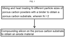
- FIG. 1 shows a preparation process flow chart of an anode material.
- compositions, step, method, product or device comprising elements listed is not limited to including these elements listed, and may also comprise other elements not specifically listed, or inherent elements of the composition, step, method, product or device.
- Part by mass refers to a basic measurement unit that represents the mass ratio relation of multiple components, and 1 part may represent any unit mass, for example, 1 g, 2.689 g, and the like. Assuming that the A component is in a parts by mass, and the B component is in b parts by mass, then the ratio of the mass of the A component to the mass of the B component is a:b, or the mass of the A component is aK, and the mass of the B component is Bk (K is an arbitrary number, representing a multiple factor). Unmistakably, the sum of parts by mass of all components is not limited to 100 parts, unlike mass fraction.
- a and/or B includes (A and B) and (A or B).
- the present disclosure provides an anode material, the anode material comprises an active material, the active material comprises a porous carbon substrate and silicon, wherein the pores and/or surface of the porous carbon substrate are distributed with the silicon; the adsorption constant C value of the anode material is C ⁇ 200, and the open porosity of an etched material of the anode material is 50%-70%.
- the adsorption constant C value is mainly set at the adsorption temperature (RT), which is generally 25°C
- the saturated vapor pressure of the adsorbate gas N 2 is p0 (unit: kPa)
- the saturated multilayer adsorption capacity at the gas equilibrium pressure p is Q (unit: mmol/g).
- the C value of strong adsorbents such as activated carbon and molecular sieves is generally >200, while the C value of the anode material in the present disclosure is ⁇ 200, the smaller the adsorption constant C, the smaller the proportion of micropores in the anode material, indicating that mesopores and macropores are mainly present in the anode material; and during the deposition process, as the vast majority of micropores have already been filled with silicon, the remaining pores in the porous carbon substrate are mainly unfilled mesopores and macropores, which are located inside the porous carbon substrate or are closed pores, as well as micropores/smaller micropores formed by the conversion of mesopores/micropores partially filled with silicon, resulting in an adsorption constant of less than 200 for the anode material, and this can not only reserve a certain amount of space to buffer the volume expansion during lithium insertion and extraction, but also ensure the amount of Si filling (that is, the proportion of Si in the anode material is
- the anode material of the present disclosure comprises silicon and a porous carbon substrate, and silicon is uniformly distributed in the skeleton of the porous carbon substrate.
- the pores in these porous carbon substrates can accommodate silicon, and the remaining pores in the anode material after filling with silicon can accommodate the volume expansion of silicon; moreover, before compounding silicon, the pores of the porous carbon substrate are mainly micropores (within the range of ⁇ 2 nm), and the opening porosity of an etched material of the anode material is 50%-70%, which is conducive to the dispersion and filling of silicon.
- the remaining pores in the porous carbon substrate are mainly unfilled mesopores and macropores, which are located inside the porous carbon substrate or are closed pores, as well as micropores/smaller micropores formed by the conversion of mesopores/micropores partially filled with silicon, resulting in an adsorption constant of less than 200 for the anode material.
- the density of the etched material of the anode material is ⁇ 1, and the density of the anode material is ⁇ 2, 50% ⁇ ( ⁇ 2- ⁇ 1)/ ⁇ 1 ⁇ 80%.
- the particle size of silicon in the anode material is 1 nm-100 nm, which can specifically be 1 nm, 10 nm, 20 nm, 50 nm, 70 nm, 100 nm, or any value between 1 nm and 100 nm.
- the open porosity of an etched material of the anode material is 50%-70%, which can specifically be 50%, 52%, 54%, 56%, 58%, 60%, 70%, or any value between 50%-70%.
- the pore size of an etched material of the anode material is 0 ⁇ m-1 ⁇ m, which can specifically be 0.001 ⁇ m, 0.01 ⁇ m, 0.05 ⁇ m, 0.1 ⁇ m, 0.3 ⁇ m, 0.5 ⁇ m, 1 ⁇ m, or any value greater than 0 ⁇ m and between 0 ⁇ m and 1 ⁇ m.
- the filling degree of silicon in pores of the porous carbon substrate is ⁇ 80%, which can specifically be 80%, 85%, 90%, 95%, or any value between 80% and 100%.
- the material density will increase; by controlling the density increase range of the anode material, a good balance can be achieved between high specific capacity, low expansion performance, and high cycling performance.
- the density of the anode material is 1.8 g/cm 3 -2.3 g/cm 3 , which can specifically be 1.8 g/cm 3 , 2.0 g/cm 3 , 2.2 g/cm 3 , 2.3 g/cm 3 , or any value between 1.8 g/cm 3 and 2.3 g/cm 3 ; and the density of an etched material of the anode material is 1 g/cm 3 -1.5 g/cm 3 , which can specifically be 1 g/cm 3 , 1.2 g/cm 3 , 1.4 g/cm 3 , 1.5 g/cm 3 , or any value between 1 g/cm 3 and 1.5 g/cm 3 .
- the anode material has a pore structure, which comprises mesopores, micropores, and macropores, wherein the volume proportion of the mesopores in all pore structures is >75%, the volume proportion of the micropores in all pore structures is ⁇ 25%, and the volume proportion of the macropores in all pore structures is ⁇ 10%.
- volume proportion of mesopores with a pore size of 2 nm-50 nm refers to the percentage of the pore volume of the mesopores in the total pore volume of the anode material
- volume proportion of micropores with a pore size ⁇ 2 nm refers to the percentage of the pore volume of the micropores in the total pore volume of the anode material
- volume proportion of macropores with a pore size >50 nm refers to the percentage of the pore volume of the macropores in the total pore volume of the anode material.
- the proportion of mesopores and macropores in the final prepared anode material is controlled within the above-mentioned range, which can provide buffer space for Si expansion during charging and discharging.
- the stress dispersion distribution is ensured, the particle strength of the anode material can be improved, and the collapse and breakage of the material structure during electrode sheet rolling or cycling can be reduced. Therefore, under the synergistic effect of the above-mentioned overall structure, the cycling performance and electrochemical performance of the material can be improved.
- the anode material has a pore structure, and the total pore volume of the anode material measured by a nitrogen adsorption method is ⁇ 0.05 cm 3 /g, which can specifically be 0.04 cm 3 /g, 0.035 cm 3 /g, 0.032 cm 3 /g, 0.030 cm 3 /g, 0.028 cm 3 /g, 0.025 cm 3 /g, 0.024 cm 3 /g or 0.02 cm 3 /g, etc., and is not limited here.
- the volume of closed pores in the anode material is ⁇ 0.2 cm 3 /g; It can be understood that the closed pore volume refers to the volume that nitrogen cannot enter during testing using a nitrogen adsorption method.
- the porous carbon substrate comprises closed pores, which are mainly mesopores based on their pore size, ensuring stress dispersion distribution, and helping to accommodate the increased volume during lithium insertion without damaging the structure of the porous carbon or significantly increasing the overall size of the anode material, and can further enhance the stability of the silicon carbon interface; and the closed pores of the porous carbon reserve buffer space for Si volume expansion during lithium insertion, and on the other hand, the lack of openings connected to the outside makes it difficult for the electrolyte to penetrate, thus eliminating the problem of continuous thickening of a SEI layer.
- the adsorption constant C value of an etched material of the anode material is 200 ⁇ C ⁇ 500, which can specifically be 200, 250 or 300, 400, 499, etc., and is not limited here.
- the calculation method for the adsorption constant C value of an etched material of the anode material is the same as the calculation method for the adsorption constant C value of the above-mentioned anode material.
- the particle size of an etched material of the anode material is 1 ⁇ m-50 ⁇ m, preferably 2 ⁇ m-20 ⁇ m. It can be understood that the particle size of an etched material of the anode material can be 1 ⁇ m, 2 ⁇ m, 3 ⁇ m, 4 ⁇ m, 5 ⁇ m, 8 ⁇ m, 10 ⁇ m, 12 ⁇ m, 15 ⁇ m, 17 ⁇ m, 20 ⁇ m, 25 ⁇ m, 30 ⁇ m, 35 ⁇ m, 40 ⁇ m, 45 ⁇ m, or 50 ⁇ m.
- the particle size of the porous carbon can also be other values between 1 ⁇ m and 50 ⁇ m.
- a nuclear magnetic resonance testing is performed on the anode material.
- the anode material In the 29 Si NMR spectrum of the anode material, there is a Si-C resonance peak between -10 ppm and 20 ppm with an intensity of D 1 , and a Si resonance peak between -90 ppm and -110 ppm with an intensity of D 2 , and D 2 /D 1 2:100.
- the outermost layer of the anode material also comprises a carbon coating layer.
- the thickness of the carbon coating layer is 1 nm-100 nm, which can specifically be 1 nm, 10 nm, 20 nm, 50 nm, 70 nm, 100 nm, or any value between 1 nm and 100 nm.
- the introduction of the carbon coating layer is mainly to improve the electronic conductivity of the anode material in the anode, further buffer the volume change of silicon, and reduce the excessive generation of SEI film on the surface of the anode material.
- the mass percentage content of silicon in the anode material is 10%-90%, preferably 20%-80%. It can be understood that the mass percentage content of silicon in anode material can be 10%, 12%, 14%, 16%, 18%, 20%, 25%, 30%, 35%, 40%, 50%, 60%, 70%, 80% or 90%. The mass percentage content of silicon in the anode material can also be other values between 10% and 90%.
- the specific surface area of the anode material is 0.5 m 2 /g-50 m 2 /g. It can be understood that the specific surface area of the anode material can be 0.5 m 2 /g, 1.0 m 2 /g, 5.0 m 2 /g, 10 m 2 /g, 13 m 2 /g, 16 m 2 /g, 20 m 2 /g, 23 m 2 /g, 26 m 2 /g, 30 m 2 /g, 33 m 2 /g, 36 m 2 /g, 40 m 2 /g, 43 m 2 /g, 46 m 2 /g, or 50 m 2 /g.
- the specific surface area of the anode material can also be other values between 0.5 m 2 /g and 50 m 2 /g.
- the average particle size D50 of the anode material is 1 ⁇ m-25 ⁇ m, preferably 2 ⁇ m-15 ⁇ m, and more preferably 3 ⁇ m-10 ⁇ m. It should be explained that when the average particle size of the anode material is ⁇ 1 ⁇ m, it can reduce the decrease in the electrode's tap density, which seriously affects its processing performance as an anode for a lithium-ion battery, reduces the problems of low electrode compaction density and low energy density, and can obtain a suitable volume specific capacity. In addition, when the average particle size of the anode material is ⁇ 25 ⁇ m, a slurry forming the electrode can be appropriately coated to a uniform thickness.
- the average particle size D 50 of the anode material can be 1 ⁇ m, 2 ⁇ m, 3 ⁇ m, 4 ⁇ m, 5 ⁇ m, 6 ⁇ m, 7 ⁇ m, 8 ⁇ m, 9 ⁇ m, 10 ⁇ m, 12 ⁇ m, 14 ⁇ m, 15 ⁇ m, 17 ⁇ m, 19 ⁇ m, 21 ⁇ m, 23 ⁇ m, or 25 ⁇ m.
- the average particle size D 50 of the anode material can also be other values between 1 ⁇ m and 25 ⁇ m.
- the anode material further comprises a carbon coating layer located on at least partial surface of the active material.
- the carbon coating layer as a shell, can mechanically constrain the active material and improve the electronic conductivity of the anode material in the anode; further the carbon coating layer allows lithium ions to pass through, but reduces the interaction between the electrolyte and internal active materials, further buffer the volume change of silicon, and reduce the excessive generation of SEI film on the surface of the anode material.
- the thickness of the carbon coating layer is 1 nm-100 nm. It can be understood that the average thickness of the coating layer can be 1 nm, 5 nm, 10 nm, 15 nm, 20 nm, 25 nm, 30 nm, 35 nm, 40 nm, 45 nm, 50 nm, 55 nm, 60 nm, 65 nm, 70 nm, 75 nm, 80 nm, 85 nm, 90 nm, 95 nm, or 100 nm. The average thickness of the coating layer can also be other values between 1 nm and 100 nm.
- the present disclosure also provides a preparation method for an anode material, as shown in FIG. 1 , which comprises:
- the present disclosure uses the preparation process to control the relevant physical characteristics of the obtained porous carbon substrate, including pore distribution, porosity, pore shape, etc. of the porous carbon substrate; and on the other hand, controlling the subsequent silicon compounding process, the anode material is further prepared on the skeleton of the prepared porous carbon substrate by adjusting the process parameters, so that the micropores in the anode material dominate, thereby alleviating the volume expansion during battery cycling and ensuring the strength of the anode material particles, reducing the probability of particle collapse and damage during cycling.
- N different particle sizes of the porous carbon powders in S1 are arranged in ascending order according to the particle size, and then numbered as C1, C2, C3..., and CN, wherein the average particle size of C1 porous carbon powder is the smallest, while the average particle size of the CN porous carbon powder is the largest.
- the ratio of D50 of the porous carbon powder with a smaller particle size to D50 of the porous carbon powder with a larger particle size in adjacent two porous carbon powders is 0.25-0.9.
- the ratio of D50 particle size of C1 porous carbon powder to that of C2 porous carbon powder is 0.25-0.9, which can specifically be 0.25, 0.3, 0.4, 0.5, 0.6, 0.7, 0.8, 0.9, or any value between 0.25 and 0.9.
- the ratio of the mass of the porous carbon powder with a smaller particle size to the mass of the porous carbon powder with a larger particle size in adjacent two porous carbon powders is 0.05-0.75.
- the ratio of the mass of C2 porous carbon powder to that of C3 porous carbon powder is 0.05-0.75, which can specifically be 0.05, 0.15, 0.25, 0.35, 0.45, 0.55, 0.65, 0.75, or any value between 0.05 and 0.75.
- D10 of the porous carbon powder with a larger particle size is not less than D90 of the porous carbon powder with a smaller particle in adjacent two porous carbon powders.
- D10 particle size of C2 porous carbon powder is not less than D90 particle size of C1 porous carbon powder
- D10 particle size of C3 porous carbon powder is not less than D90 particle size of C2 porous carbon powder.
- the raw material of the porous carbon substrate comprises three different particle sizes of porous carbon powders. Among these three different particle sizes of porous carbon powders, they are classified into C1, C2, and C3 in descending order of particle size.
- the ratio of D50 particle size of C3:C2:C1 is (4-7):(2-3.5):1, which can specifically be 4:2:1, 4:3.5:1, 5:2:1, 5:3.5:1, 6:2:1, 6:3:1, 6:3.5:1, 7:2:1, 7:3.5:1, or any value between (4-7):(2-3.5):1.
- the mass ratio of C3:C2:C1 is (18-25):(6-12):1, which can specifically be 18:6:1, 18:12:1, 20:6:1, 20:10:1, 20:12:1, 23:6:1, 23:12:1, 25:6:1, 25:12:1, or any value between (18-25):(6-12):1.
- the average particle size of C3, C2, and C1, i.e. D50 is 100 ⁇ m-500 ⁇ m, 70 ⁇ m-400 ⁇ m, and 20 ⁇ m-130 ⁇ m, respectively.
- the average pore size of the porous carbon substrate prepared from three different particle sizes of porous carbon powders is 2 nm-50 nm, which can be 2 nm, 10 nm, 20 nm, 30 nm, 40 nm, 50 nm, or any value between 2 nm and 50 nm.
- the method for optimizing the particle size distribution preferably three-level distribution of the porous carbon powder in this disclosure involves using three different particle sizes of porous carbon powders as raw materials for the porous carbon substrate.
- porous carbon particles with medium particle size will fill the gaps between porous carbon particles with large particle size
- porous carbon particles with small particle size will further fill the gaps between porous carbon particles with large particle size and porous carbon particles with medium particle size. If only one particle size of porous carbon powder raw material is used to prepare a porous carbon substrate, there will be large pores between these porous carbon particles, that is, the pores of the porous carbon substrate are large.
- the binder in S1 can choose to use polyvinyl butyral.
- the ratio of the total mass of the N different particle sizes of the porous carbon powder in S1 to the mass of the binder is (5-20):1, which can specifically be 5:1, 10:1, 15:1, 20:1, or any value between (5-20):1.
- An appropriate amount of binder can mix and adhere porous carbon particles together. Too much binder may lead to a decrease in the conductivity of the material, while too little may result in a decrease in the stability of the anode material particles.
- By controlling the amount of binder added it is possible to increase the specific capacity of the anode material while ensuring effective bonding and compression of porous carbon particles together, thereby improving the electrochemical performance of the material.
- the mixing mode in S1 includes at least one of VC mixing, manual mixing, room temperature film pressing and spray drying.
- the heat treating in S1 comprises: heating, pressurizing, and cooling the mixed material after mixing to obtain a porous carbon substrate.
- the mixed material after the first mixing can be laid flat in a mold, and then the mold can be heated, pressurized, cooled, and de-molded to obtain a porous carbon substrate. And before the mixed material is laid flat on the mold, a mold release agent needs to be applied to the inner surface of the mold to facilitate the rapid extraction of the porous carbon substrate.
- the mold includes a steel mold.
- the temperature for heating is 50 °C-500 °C, which can specifically be 50°C, 100°C, 200°C, 300°C, 400°C, 500°C, or any value between 50°C and 500 °C; and the time is 0.5 h-5 h, which can specifically be 0.5 h, 1 h, 2 h, 3 h, 4 h, 5 h, or any value between 0.5 h and 5 h.
- the pressure for pressurizing is 5 MPa-50 MPa, which can specifically be 5 MPa, 10 MPa, 20 MPa, 30 MPa, 40 MPa, 50 MPa, or any value between 5 MPa and 50 MPa.
- the time is 0.2 h-10 h, which can specifically be 0.5 h, 1 h, 2 h, 3 h, 4 h, 5 h, or any value between 0.5 h and 5 h.
- the correct selection of the porous carbon substrate is crucial for achieving silicon infiltration into the porous carbon substrate. If the porosity and pore size of the substrate are too large, the density of a composite material produced by silicon infiltration in the substrate will be low; and if they are too small, it will be difficult to deeply introduce a silicon source gas into deeper areas of pores, so that the gas can form silicon in them. Therefore, one of the research objectives of the present disclosure is to find suitable process parameters for deeply introducing silicon into the pores of the porous carbon substrate used, and to achieve a correct balance between good mechanical strength and electrochemical performance in the prepared composite material.
- the compounding method in S2 comprises any one of a chemical vapor infiltration method, a dry mixing process, and a wet mixing process, with the chemical vapor infiltration method being more preferred.
- the dry mixing process involves performing ball milling and dry mixing to the porous carbon substrate with silicon, while the wet mixing process involves mixing the porous carbon substrate with a silicon-containing solution.
- the chemical vapor infiltration method used in the compounding of the present disclosure comprises: placing the porous carbon substrate in an infiltration furnace, vacuuming the infiltration furnace, heating it to the reaction temperature, introducing a silicon source gas, and performing infiltration deposition.
- a chemical vapor infiltration method is used to perform a thermal decomposition reaction to a reaction gas, so that silicon is deposited on the surface and/or pores of the porous carbon substrate to obtain an anode material.
- the reaction gas comprises a silane gas, hydrogen, and an inert gas.
- the reaction gas comprises a silane gas, which comprises at least one of Si n H (2n+2) and Si n H (2n+2) Z (2n+2)-m , wherein n ⁇ 1, m ⁇ 2n+2, and Z comprises at least one halogen element from F, Cl, Br and I.
- the reaction temperature of the thermal decomposition is 400 °C-800 °C, which can specifically be 400 °C, 500°C, 600°C, 700°C, 800°C, or any value between 400°C and 800°C.
- the deposition time is 5 h-500 h, which can specifically be 5 h, 10 h, 100 h, 250 h, 500 h, or any value between 5 h and 500 h.
- the pressure of the reaction system before introducing the reaction gas is 1 Pa-20 Pa, which can specifically be 1 Pa, 5 Pa, 10 Pa, 15 Pa, 20 Pa, or any value between 1 Pa and 20 Pa.
- the oxygen content in the reaction system is ⁇ 0.5%.
- the total pressure of the reaction system is 0.5 kPa-50 kPa, which can specifically be 0.5 kPa, 1 kPa, 5 kPa, 10 kPa, 20 kPa, 30 kPa, 40 kPa, 50 kPa, or any value between 0.5 kPa and 50 kPa.
- the heating curve during heating includes raising the temperature at a heating rate of 1 °C/min-50 °C/min, which can specifically be 1 °C/min, 10 °C/min, 20 °C/min, 30 °C/min, 40 °C/min, 50 °C/min, or any value between 1 °C/min and 50 °C/min to 10 °C-20 °C below the desired reaction temperature, then continuing heating at a heating rate of 0.05 °C/min-0.5 °C/min to the desired reaction temperature, and then being more preferred to continue heating at a heating rate of 0.1 °C/min.
- the key to improving the densification rate of the chemical vapor infiltration (CVI) method is to ensure that the silane gas does not decompose and deposit before entering the pores of the porous carbon, but rapidly decomposes and deposits after entering the pores.
- CVI chemical vapor infiltration
- vacuuming is first applied to make the pressure inside and outside the porous carbon substrate close to zero. Then, the temperature inside the infiltration furnace is rapidly raised to about 10 °C-20 °C below the gas decomposition temperature at a heating rate of 1 °C/min-50 °C/min. Then, the temperature is slowly raised to the gas decomposition temperature at a heating rate of 0.1 °C/min, ensuring that the temperature inside and outside the porous carbon substrate remains consistent and the thermodynamic conditions are stable. Then, a silane gas diluted with inert gases such as H2 and argon are introduced into the infiltration furnace, which can ensure the uniform diffusion of the silane gas inside the porous carbon and facilitate its uniform infiltration.
- inert gases such as H2 and argon
- performing infiltration deposition further comprises: when the silicon source gas flows from the front end to the end of the porous carbon substrate, a movable heating coil is used to heat the end of the porous carbon substrate to the reaction temperature of the gas, so that the silicon source gas undergoes densification reaction on the porous carbon substrate at the end, and performs infiltration deposition; and then the movable heating coil is gradually moved from the end to the front end, so that every part of the porous carbon substrate undergoes densification infiltration deposition.
- porous carbon substrate in the infiltration furnace ensures that every part of the porous carbon substrate can undergo densification reaction as much as possible, resulting in a high-density anode material and uniform distribution of silicon on the porous carbon substrate.
- the molar ratio of hydrogen to the silane gas is (5-20):1, which can specifically be 5:1, 10:1, 15:1, 20:1, or any value between (5-20):1. It can be understood that in a silicon source gas, argon is mainly a diluent gas, while hydrogen is both a diluent gas and a carrier gas.
- the gas flow ratio of hydrogen as a diluent gas to a hydrogen as a carrier gas is (3-10):1, which can specifically be 3:1, 5:1, 8:1, 10:1, or any value between (3-10):1.
- the flow rate of hydrogen is 100 mL/min-500 mL/min, which can specifically be 100 mL/min, 200 mL/min, 300 mL/min, 400 mL/min, 500 mL/min, or any value between 100 mL/min and 500 mL/min.
- the flow rate of argon is between 200 mL/min-500 mL/min, which can specifically be 200 mL/min, 300 mL/min, 400 mL/min, 500 mL/min, or any value between 200 mL/min and 500 mL/min.
- the infiltration deposition after the infiltration deposition is completed, it further comprises: stopping the power supply and introducing a silicon source gas, closing a vacuum system used for vacuuming, and continuously introducing argon into an infiltration furnace until the pressure inside the infiltration furnace reaches atmospheric pressure, then opening a gas release valve to cool the temperature of the infiltration furnace to room temperature, and then stopping the introduction of argon to remove the prepared product.
- the anode material prepared by a chemical vapor infiltration has a porosity of approximately 10%-15%, wherein silicon is dispersed and embedded in the porous carbon substrate.
- the method further comprises: using solid-phase carbon coating treatment, liquid-phase carbon coating treatment, or gas-phase carbon coating treatment, carbon source and the intermediate product prepared after the compounding are carried out carbon coating treatment.
- the coating treatment comprises the following steps: mixing the intermediate product with a carbon source, controlling the thermal cracking of the carbon source in a protective atmosphere to form a carbon coating layer on the surface of the intermediate product.
- the carbon source comprises a gas-phase carbon source.
- the carbon source comprises a gas-phase carbon source, which comprises at least one of methane, acetylene, ethylene, ethane, propane, propylene, propyne, acetone, and benzene.
- the carbon source comprises a solid-phase carbon source.
- the carbon source comprises a solid-phase carbon source
- the solid-phase carbon source comprises a solid-phase organic carbon source
- the carbon source comprises a solid-phase carbon source
- the solid-phase carbon source comprises at least one of citric acid, glucose, asphalt, phenolic resin, and furfural resin.
- the carbon source includes a liquid-phase carbon source.
- the carbon source comprises a liquid-phase carbon source
- the liquid-phase carbon source comprises a liquid-phase organic carbon source
- the carbon source comprises a liquid-phase carbon source
- the liquid-phase carbon source comprises at least one of n-hexane, toluene, benzene, xylene, methanol, ethanol, propanol, butanol, pentanol, acetone, butanone, 2-pentanone, methyl acetate, ethyl acetate, propyl acetate, butyl acetate, and pentyl acetate.
- the temperature of thermal cracking is 600 °C-1200 °C.
- the heating rate of thermal cracking is 0.1 °C/min-50 °C/min.
- the anode material prepared in the present disclosure can be used as an anode material applied in a lithium-ion battery. Specifically, after applying the anode material in the lithium-ion battery, its first reversible specific capacity is ⁇ 2000 mAh/g, the expansion rate is ⁇ 38% after 50 cycles of circulation, and the capacity retention rate is >87%. According to in-situ XRD data, there are always silicon characteristic peaks of (111), (220), and (311) when the anode material is initially discharged to 0.05 V vs Li/Li + ; and at 0.01 V vs Li/Li + , a c-Li 15 Si 4 peak will appear in the anode material.
- the surface of silicon is lithiated to form Li x Si, while the interior is crystalline silicon.
- Li x Si on the silicon surface delithiates to form amorphous Si(a-Si), while the interior remains crystalline silicon.
- the present disclosure performs adsorption and desorption tests on a porous carbon substrate prepared using three different particle sizes of porous carbon powders.
- the adsorption and desorption curves exhibit Type I, which exhibits a typical Langmuir isotherm (comprising narrow microporous materials with pore widths less than 1 nm and mixtures containing narrow mesoporous materials with pore widths less than 2.5 nm); and the adsorption and desorption curves of the prepared anode material is IV(a) type, which is accompanied by hysteresis loop after capillary condensation (these are the typical adsorption and desorption curves of mesoporous materials).
- the porosity can be obtained by calculating the product of the number of pores per unit weight of the material (cm 3 /g) and the bulk density (g/cm 3 ).
- the (bulk) density can be obtained by dividing the mass of the material by the volume of the sample; and the number of pores per unit weight can be further measured using conventional equipment or a mercury porosimeter under known conditions.
- the oxygen content in the infiltration furnace can be tested using the Bacharach model 0024-7341 oxygen/carbon monoxide meter.
- the elemental ratios of Si, O, and C in the material can be characterized and analyzed to determine the phase composition in the material.
- a laser particle size analyzer is used to test D50, D90, and D10 of the material particle size, and then the value of (D90-D10)/D50 is calculated to ensure that the material particle size has a symmetrical distribution similar to a normal distribution.
- the cumulative 10% diameter is D10
- the cumulative 50% diameter is D50
- the cumulative 90% diameter is D90.
- TriStar 3000 specific surface area and pore size analyzer equipment from the Micromeritics Instrument Corporation is used to test the specific surface area of the material.
- the XRD peaks of the material are obtained using a Panaco X'pert Pro X-ray diffractometer, and then the Si peak in XRD is fitted using Jade 6.5 software to obtain the size of the silicon microcrystals.
- 29Si MAS NMR standard silicon structure chemical shift 29Si MAS NMR (29Si Magic Angle Spinning Nuclear Magnetic Resonance Spectroscopy) is used, and the instrument model is Bruker AV 300 nuclear magnetic resonance spectrometer.
- single pulses are used during the testing process instead of cross polarization methods.
- the pulse width is 4.5 ut
- ⁇ is 54.7°
- the relaxation delay i.e. the time delay between two samples
- the rotational speed is 7 kHz.
- TMS is used as a chemical shift standard for measuring.
- SEM or TEM image measurement of silicon particle size SEM or TEM images of the anode material are saved. Nano Measurer software is run, the SEM or TEM image that needs to be counted is opened, the ruler is set, and the mouse is dragged to mark the particles on the image to obtain their particle size. Five 100 ⁇ m * 75 ⁇ m regions are randomly selected, and 20 nano silicon particles within each region are randomly selected for particle size statistics to obtain their particle size distribution range. Origin software is used to fit the obtained granularity values with a normal distribution to obtain the mean and standard deviation, with a standard deviation of ⁇ 0.2.
- Weight method for testing silicon content a box type atmosphere furnace is used to burn the sample in an O 2 atmosphere, causing the silicon in the sample to react into SiO 2 , and after C combustion, it becomes CO 2 and is discharged, then the sample is weighed, and the silicon content is calculated.
- Microperetics ASAP 2460 is used for microporous and mesoporous analysis. At liquid nitrogen temperature, the equilibrium adsorption capacity of nitrogen on the surface of an object is related to its pore size and other characteristics. Combining the law of adsorption capacity changing with relative pressure during the adsorption process, multiple models can be fitted for pore size calculation. The report generated by the software uses density functional theory (DFT) methods to calculate pore size distribution, total pore volume, and pore volume within a certain range.
- DFT density functional theory
- the testing method for the open porosity of an etched material of the anode material about 0.5 g of the anode material sample is weighed and placed in a platinum crucible, 5 mL of HNO 3 and 10 mL of HF mixed acid are added, and after the mixed acid reacts stably with the sample, the platinum crucible is placed on a 350 °C electric heating plate to heat and remove the acid until hydrofluoric acid evaporates without emitting white smoke; and after the crucible cools down, 6 mL of HCl is added and heated until the residue is completely dissolved, the rest is an etched anode material.
- Open porosity refers to the ratio of the volume of open pores in a sample to the total volume of the sample. Open pores refer to pores with an open edge that can be connected to liquids or gases in the environment. In practical applications, open porosity is commonly used to describe the properties and performance of materials such as porous media, filter materials, and magnetic materials.
- the measurement of open porosity is usually carried out using methods such as gas infiltration and liquid displacement.
- gas infiltration method is used to measure the average diameter and pore volume of open pores, and then the open porosity is calculated through a formula.
- liquid displacement method measures the volume of open pores by immersing them in liquid, and the open porosity can also be obtained.
- Closed porosity refers to the ratio of the volume of closed pores in a sample to the total volume of the sample. Closed pores refer to pores with closed edges that are not connected to liquids or gases in the environment, and are generally used in geological exploration and other fields.
- the measurement of closed porosity usually uses methods such as density method and helium measurement method: for example, taking anhydrous ethanol with a volume of V1 into a measuring cylinder, immersing the dry material in it for 5 min, vacuum pumping until there are no bubbles in the ethanol, and recording the ethanol volume as V2 at this time; and taking out the material and recording the volume as V3 at this time.
- the porosity is calculated by: (V1-V3)/(V2-V3) * 100%. 3 samples are measured per group and the average is taken.
- the pore volume testing method has been added in the specific surface area test and will not be repeated.
- Lithium ion battery performance testing preparing an anode slurry with anode material, conductive carbon black Super-P (5)+conductive graphite SFG-6(10), and aqueous dispersion of acrylonitrile multicomponent copolymer (LA133 water-based binder) in a mass ratio of 75:15:10, coating it on copper foil, and drying it to prepare an anode sheet.
- a button type battery is assembled in a glove box filled with Ar gas, using lithium metal sheets as the counter electrode.
- the first reversible specific capacity and ICE of the button battery are obtained by performing charging and discharging tests on the button battery within the charging and discharging range of 0.01-5 V at a current density of 0.1 C.
- An anode slurry is prepared with the mixture of anode material and graphite, conductive carbon black Super-P, conductive carbon black KS-6, carboxymethyl cellulose sodium CMC, and styrene butadiene rubber SBR in a mass ratio of 92:2:2:2:2, coated on copper foil, and dried to prepare an anode sheet.
- the proportion of anode material and graphite in the mixture of anode material and graphite is determined by the first reversible specific capacity of the two and the capacity required for their combination.
- a button type battery is assembled in a glove box filled with Ar gas, using lithium metal sheets as the counter electrode. 50 repeated charging and discharging tests are performed on the button type battery with a current density of 1 C in the charging and discharging range of 0.01 V-5 V to obtain the capacity retention rate and electrode sheet thickness expansion rate of the battery after 50 cycles.
- This embodiment provided an anode material, and the specific preparation method therefor comprised:
- This embodiment provided an anode material, and the specific preparation method therefor comprised:
- This embodiment provided an anode material, and the specific preparation method therefor comprised:
- This embodiment provided an anode material, and the specific preparation method therefor comprised:
- This embodiment provided an anode material, and the specific preparation method therefor comprised:
- the anode materials prepared in Embodiments 1-5 and Comparative Embodiments 1-6 were used as anode materials in lithium-ion batteries, and the test data shown in Tables 1 and 2 were obtained.
Landscapes
- Chemical & Material Sciences (AREA)
- Chemical Kinetics & Catalysis (AREA)
- Electrochemistry (AREA)
- General Chemical & Material Sciences (AREA)
- Engineering & Computer Science (AREA)
- Manufacturing & Machinery (AREA)
- Composite Materials (AREA)
- Materials Engineering (AREA)
- Inorganic Chemistry (AREA)
- Battery Electrode And Active Subsutance (AREA)
Applications Claiming Priority (2)
| Application Number | Priority Date | Filing Date | Title |
|---|---|---|---|
| CN202211700443.2A CN118263409A (zh) | 2022-12-28 | 2022-12-28 | 负极材料及其制备方法和锂离子电池 |
| PCT/CN2023/128230 WO2024139653A1 (fr) | 2022-12-28 | 2023-10-31 | Matériau d'électrode négative, son procédé de préparation et batterie au lithium-ion |
Publications (2)
| Publication Number | Publication Date |
|---|---|
| EP4576251A1 true EP4576251A1 (fr) | 2025-06-25 |
| EP4576251A4 EP4576251A4 (fr) | 2026-03-25 |
Family
ID=91601185
Family Applications (1)
| Application Number | Title | Priority Date | Filing Date |
|---|---|---|---|
| EP23909586.2A Pending EP4576251A4 (fr) | 2022-12-28 | 2023-10-31 | Matériau d'électrode négative, son procédé de préparation et batterie au lithium-ion |
Country Status (4)
| Country | Link |
|---|---|
| US (1) | US20250149565A1 (fr) |
| EP (1) | EP4576251A4 (fr) |
| CN (2) | CN118263409A (fr) |
| WO (1) | WO2024139653A1 (fr) |
Cited By (1)
| Publication number | Priority date | Publication date | Assignee | Title |
|---|---|---|---|---|
| CN120878826A (zh) * | 2025-09-25 | 2025-10-31 | 重庆长安汽车股份有限公司 | 用于固态电池的低膨胀多孔硅负极材料及锂离子固态电池 |
Families Citing this family (4)
| Publication number | Priority date | Publication date | Assignee | Title |
|---|---|---|---|---|
| CN118039846A (zh) * | 2024-02-02 | 2024-05-14 | Oppo广东移动通信有限公司 | 负极活性颗粒及其制备方法、电池及电子设备 |
| CN118651845B (zh) * | 2024-08-19 | 2025-01-14 | 贝特瑞新材料集团股份有限公司 | 碳材料、复合负极材料及锂离子电池 |
| CN119050331B (zh) * | 2024-09-29 | 2025-10-17 | 贝特瑞新材料集团股份有限公司 | 负极材料、负极片和二次电池 |
| CN120943238A (zh) * | 2024-09-30 | 2025-11-14 | 江西紫宸科技有限公司 | 一种多孔碳、硅碳负极材料、电极片、锂离子电池和用电器 |
Family Cites Families (7)
| Publication number | Priority date | Publication date | Assignee | Title |
|---|---|---|---|---|
| CN119419246A (zh) * | 2015-08-28 | 2025-02-11 | 14集团技术公司 | 具有极其持久的锂嵌入的新型材料及其制造方法 |
| CN107293700B (zh) * | 2016-03-31 | 2020-08-07 | 比亚迪股份有限公司 | 一种锂离子电池负极活性材料及其制备方法、负极和电池 |
| CN106450192A (zh) * | 2016-10-14 | 2017-02-22 | 浙江天能能源科技股份有限公司 | 一种锂离子电池用硅碳复合材料及其制备方法和应用 |
| JP2020501301A (ja) * | 2016-11-23 | 2020-01-16 | ジーアールエスティー・インターナショナル・リミテッド | 2次バッテリーのためのアノードスラリーの作製方法 |
| CN115699368A (zh) * | 2020-05-28 | 2023-02-03 | 昭和电工株式会社 | 锂离子二次电池用负极材料及其用途 |
| CN115132997A (zh) * | 2022-07-13 | 2022-09-30 | Oppo广东移动通信有限公司 | 负极材料及其制备方法、电池和电子设备 |
| CN115207331B (zh) * | 2022-08-26 | 2024-09-13 | 北京理工大学 | 多孔核壳结构的硅基负极材料及其制备方法与锂离子电池 |
-
2022
- 2022-12-28 CN CN202211700443.2A patent/CN118263409A/zh active Pending
-
2023
- 2023-10-31 EP EP23909586.2A patent/EP4576251A4/fr active Pending
- 2023-10-31 WO PCT/CN2023/128230 patent/WO2024139653A1/fr not_active Ceased
- 2023-10-31 CN CN202380065391.2A patent/CN120019500A/zh active Pending
-
2025
- 2025-01-08 US US19/013,923 patent/US20250149565A1/en active Pending
Cited By (1)
| Publication number | Priority date | Publication date | Assignee | Title |
|---|---|---|---|---|
| CN120878826A (zh) * | 2025-09-25 | 2025-10-31 | 重庆长安汽车股份有限公司 | 用于固态电池的低膨胀多孔硅负极材料及锂离子固态电池 |
Also Published As
| Publication number | Publication date |
|---|---|
| CN120019500A (zh) | 2025-05-16 |
| EP4576251A4 (fr) | 2026-03-25 |
| US20250149565A1 (en) | 2025-05-08 |
| CN118263409A (zh) | 2024-06-28 |
| WO2024139653A1 (fr) | 2024-07-04 |
Similar Documents
| Publication | Publication Date | Title |
|---|---|---|
| EP4576251A1 (fr) | Matériau d'électrode négative, son procédé de préparation et batterie au lithium-ion | |
| Wang et al. | Synthesis of a novel porous silicon microsphere@ carbon core-shell composite via in situ MOF coating for lithium ion battery anodes | |
| Sun et al. | A hybrid ZnO/Si/porous-carbon anode for high performance lithium ion battery | |
| Song et al. | Porous nano-Si/carbon derived from zeolitic imidazolate frameworks@ nano-Si as anode materials for lithium-ion batteries | |
| Tian et al. | Micro-sized nano-porous Si/C anodes for lithium ion batteries | |
| Wang et al. | Controllable synthesis of SnO 2@ C yolk–shell nanospheres as a high-performance anode material for lithium ion batteries | |
| Wang et al. | Conversion of diatomite to porous Si/C composites as promising anode materials for lithium-ion batteries | |
| Shi et al. | Understanding the impact mechanism of the thermal effect on the porous silicon anode material preparation via magnesiothermic reduction | |
| CN115863600B (zh) | 一种硅碳负极材料及其制备方法和应用 | |
| Yan et al. | Metal-organic frameworks-derived CoMOF-D@ Si@ C core-shell structure for high-performance lithium-ion battery anode | |
| Wu et al. | Carbon coated mesoporous Si anode prepared by a partial magnesiothermic reduction for lithium-ion batteries | |
| Zhang et al. | Influence of sintering temperature and graphene additives on the electrochemical performance of porous Li4Ti5O12 anode for lithium ion capacitor | |
| Du et al. | In situ synthesis of stable silicon carbide-reinforced silicon nanosheets from organoclay for high-performance lithium-ion battery anodes | |
| Shen et al. | Carbon-coated hierarchically porous silicon as anode material for lithium ion batteries | |
| US20250038184A1 (en) | Composite negative electrode material, and preparation method therefor and use thereof | |
| Deng et al. | Three-dimensionally hierarchical Co3O4/Carbon composites with high pseudocapacitance contribution for enhancing lithium storage | |
| Li et al. | Controllable synthesis of 3D hierarchical cactus-like ZnCo2O4 films on nickel foam for high-performance asymmetric supercapacitors | |
| Fu et al. | Temperature-induced microstructure optimization of Co3O4 for the achievement of a high-areal-capacity carbon cloth-based lithium ion battery anode | |
| Fan et al. | Insights to the variation of oxygen content and reasons for improved electrochemical performance of annealing SiOx anodes for Li-ion battery | |
| CN106252622B (zh) | 一种氧化硅/碳复合纳米线负极材料、制备方法及锂离子电池 | |
| CN103078089B (zh) | 一种高容量锂离子电池用复合石墨负极材料及其制备方法 | |
| Zhang et al. | Hierarchical mesoporous Li2FeSiO4/C sheaf-rods as a high-performance lithium-ion battery cathode | |
| CN109250707A (zh) | 一种利用废旧轮胎制备的石墨烯材料及制备方法 | |
| Silvestri et al. | NaAlH4 nanoconfinement in a mesoporous carbon for application in lithium ion batteries | |
| Liang et al. | Facile synthesis of ceramic SiC-based nanocomposites and the superior electrochemical lithiation/delithiation performances |
Legal Events
| Date | Code | Title | Description |
|---|---|---|---|
| STAA | Information on the status of an ep patent application or granted ep patent |
Free format text: STATUS: THE INTERNATIONAL PUBLICATION HAS BEEN MADE |
|
| PUAI | Public reference made under article 153(3) epc to a published international application that has entered the european phase |
Free format text: ORIGINAL CODE: 0009012 |
|
| STAA | Information on the status of an ep patent application or granted ep patent |
Free format text: STATUS: REQUEST FOR EXAMINATION WAS MADE |
|
| 17P | Request for examination filed |
Effective date: 20250317 |
|
| AK | Designated contracting states |
Kind code of ref document: A1 Designated state(s): AL AT BE BG CH CY CZ DE DK EE ES FI FR GB GR HR HU IE IS IT LI LT LU LV MC ME MK MT NL NO PL PT RO RS SE SI SK SM TR |
|
| A4 | Supplementary search report drawn up and despatched |
Effective date: 20260220 |
|
| RIC1 | Information provided on ipc code assigned before grant |
Ipc: H01M 4/36 20060101AFI20260216BHEP Ipc: H01M 4/583 20100101ALI20260216BHEP Ipc: H01M 4/134 20100101ALI20260216BHEP Ipc: H01M 4/1393 20100101ALI20260216BHEP |
|
| DAX | Request for extension of the european patent (deleted) | ||
| RAV | Requested validation state of the european patent: fee paid |
Extension state: MA Effective date: 20250317 |