EP4576298A1 - Elektrochemische vorrichtung und elektrische vorrichtung - Google Patents
Elektrochemische vorrichtung und elektrische vorrichtung Download PDFInfo
- Publication number
- EP4576298A1 EP4576298A1 EP22956805.0A EP22956805A EP4576298A1 EP 4576298 A1 EP4576298 A1 EP 4576298A1 EP 22956805 A EP22956805 A EP 22956805A EP 4576298 A1 EP4576298 A1 EP 4576298A1
- Authority
- EP
- European Patent Office
- Prior art keywords
- winding
- positive electrode
- negative electrode
- electrochemical device
- wound
- Prior art date
- Legal status (The legal status is an assumption and is not a legal conclusion. Google has not performed a legal analysis and makes no representation as to the accuracy of the status listed.)
- Pending
Links
Images




Classifications
-
- H—ELECTRICITY
- H01—ELECTRIC ELEMENTS
- H01M—PROCESSES OR MEANS, e.g. BATTERIES, FOR THE DIRECT CONVERSION OF CHEMICAL ENERGY INTO ELECTRICAL ENERGY
- H01M10/00—Secondary cells; Manufacture thereof
- H01M10/05—Accumulators with non-aqueous electrolyte
- H01M10/058—Construction or manufacture
- H01M10/0587—Construction or manufacture of accumulators having only wound construction elements, i.e. wound positive electrodes, wound negative electrodes and wound separators
-
- H—ELECTRICITY
- H01—ELECTRIC ELEMENTS
- H01M—PROCESSES OR MEANS, e.g. BATTERIES, FOR THE DIRECT CONVERSION OF CHEMICAL ENERGY INTO ELECTRICAL ENERGY
- H01M10/00—Secondary cells; Manufacture thereof
- H01M10/04—Construction or manufacture in general
- H01M10/0431—Cells with wound or folded electrodes
-
- H—ELECTRICITY
- H01—ELECTRIC ELEMENTS
- H01M—PROCESSES OR MEANS, e.g. BATTERIES, FOR THE DIRECT CONVERSION OF CHEMICAL ENERGY INTO ELECTRICAL ENERGY
- H01M10/00—Secondary cells; Manufacture thereof
- H01M10/05—Accumulators with non-aqueous electrolyte
- H01M10/052—Li-accumulators
-
- H—ELECTRICITY
- H01—ELECTRIC ELEMENTS
- H01M—PROCESSES OR MEANS, e.g. BATTERIES, FOR THE DIRECT CONVERSION OF CHEMICAL ENERGY INTO ELECTRICAL ENERGY
- H01M10/00—Secondary cells; Manufacture thereof
- H01M10/05—Accumulators with non-aqueous electrolyte
- H01M10/058—Construction or manufacture
-
- H—ELECTRICITY
- H01—ELECTRIC ELEMENTS
- H01M—PROCESSES OR MEANS, e.g. BATTERIES, FOR THE DIRECT CONVERSION OF CHEMICAL ENERGY INTO ELECTRICAL ENERGY
- H01M50/00—Constructional details or processes of manufacture of the non-active parts of electrochemical cells other than fuel cells, e.g. hybrid cells
- H01M50/10—Primary casings; Jackets or wrappings
- H01M50/172—Arrangements of electric connectors penetrating the casing
- H01M50/174—Arrangements of electric connectors penetrating the casing adapted for the shape of the cells
- H01M50/179—Arrangements of electric connectors penetrating the casing adapted for the shape of the cells for cells having curved cross-section, e.g. round or elliptic
-
- H—ELECTRICITY
- H01—ELECTRIC ELEMENTS
- H01M—PROCESSES OR MEANS, e.g. BATTERIES, FOR THE DIRECT CONVERSION OF CHEMICAL ENERGY INTO ELECTRICAL ENERGY
- H01M50/00—Constructional details or processes of manufacture of the non-active parts of electrochemical cells other than fuel cells, e.g. hybrid cells
- H01M50/50—Current conducting connections for cells or batteries
- H01M50/531—Electrode connections inside a battery casing
-
- H—ELECTRICITY
- H01—ELECTRIC ELEMENTS
- H01M—PROCESSES OR MEANS, e.g. BATTERIES, FOR THE DIRECT CONVERSION OF CHEMICAL ENERGY INTO ELECTRICAL ENERGY
- H01M50/00—Constructional details or processes of manufacture of the non-active parts of electrochemical cells other than fuel cells, e.g. hybrid cells
- H01M50/50—Current conducting connections for cells or batteries
- H01M50/531—Electrode connections inside a battery casing
- H01M50/538—Connection of several leads or tabs of wound or folded electrode stacks
-
- H—ELECTRICITY
- H01—ELECTRIC ELEMENTS
- H01M—PROCESSES OR MEANS, e.g. BATTERIES, FOR THE DIRECT CONVERSION OF CHEMICAL ENERGY INTO ELECTRICAL ENERGY
- H01M10/00—Secondary cells; Manufacture thereof
- H01M10/05—Accumulators with non-aqueous electrolyte
- H01M10/052—Li-accumulators
- H01M10/0525—Rocking-chair batteries, i.e. batteries with lithium insertion or intercalation in both electrodes; Lithium-ion batteries
-
- H—ELECTRICITY
- H01—ELECTRIC ELEMENTS
- H01M—PROCESSES OR MEANS, e.g. BATTERIES, FOR THE DIRECT CONVERSION OF CHEMICAL ENERGY INTO ELECTRICAL ENERGY
- H01M50/00—Constructional details or processes of manufacture of the non-active parts of electrochemical cells other than fuel cells, e.g. hybrid cells
- H01M50/10—Primary casings; Jackets or wrappings
- H01M50/102—Primary casings; Jackets or wrappings characterised by their shape or physical structure
- H01M50/107—Primary casings; Jackets or wrappings characterised by their shape or physical structure having curved cross-section, e.g. round or elliptic
-
- Y—GENERAL TAGGING OF NEW TECHNOLOGICAL DEVELOPMENTS; GENERAL TAGGING OF CROSS-SECTIONAL TECHNOLOGIES SPANNING OVER SEVERAL SECTIONS OF THE IPC; TECHNICAL SUBJECTS COVERED BY FORMER USPC CROSS-REFERENCE ART COLLECTIONS [XRACs] AND DIGESTS
- Y02—TECHNOLOGIES OR APPLICATIONS FOR MITIGATION OR ADAPTATION AGAINST CLIMATE CHANGE
- Y02E—REDUCTION OF GREENHOUSE GAS [GHG] EMISSIONS, RELATED TO ENERGY GENERATION, TRANSMISSION OR DISTRIBUTION
- Y02E60/00—Enabling technologies; Technologies with a potential or indirect contribution to GHG emissions mitigation
- Y02E60/10—Energy storage using batteries
-
- Y—GENERAL TAGGING OF NEW TECHNOLOGICAL DEVELOPMENTS; GENERAL TAGGING OF CROSS-SECTIONAL TECHNOLOGIES SPANNING OVER SEVERAL SECTIONS OF THE IPC; TECHNICAL SUBJECTS COVERED BY FORMER USPC CROSS-REFERENCE ART COLLECTIONS [XRACs] AND DIGESTS
- Y02—TECHNOLOGIES OR APPLICATIONS FOR MITIGATION OR ADAPTATION AGAINST CLIMATE CHANGE
- Y02P—CLIMATE CHANGE MITIGATION TECHNOLOGIES IN THE PRODUCTION OR PROCESSING OF GOODS
- Y02P70/00—Climate change mitigation technologies in the production process for final industrial or consumer products
- Y02P70/50—Manufacturing or production processes characterised by the final manufactured product
Definitions
- This application relates to the technical field of batteries, and specifically, to an electrochemical device and an electric device.
- This application provides an electrochemical device and an electric device to improve the service life of the electrochemical device.
- this application provides an electrochemical device, including a housing and a wound electrode assembly; where an accommodating space is formed inside the housing; and the wound electrode assembly accommodated in the accommodating space, where the wound electrode assembly has a winding centerline, the wound electrode assembly includes a positive electrode plate and a negative electrode plate, the positive electrode plate includes a positive electrode active material layer, and along a winding direction of the positive electrode plate, the positive electrode active material layer has a positive electrode winding starting end and a positive electrode winding ending end; where when observed along a direction of the winding centerline, a straight line passing through the positive electrode winding ending end and orthogonal to the winding centerline is defined as a first reference line, a straight line orthogonal to the first reference line and orthogonal to the winding centerline is defined as a second reference line, and a straight line passing through the positive electrode winding starting end and orthogonal to the winding centerline is defined as a third reference line, where a zero or acute angle ⁇ exists between the third reference line and
- the inventor of this application has found through research that during the charge of an electrochemical device, an electrode plate undergoes volume expansion. Due to a smaller curvature of an inner winding circle, the required radius change for the inner winding circle is larger to reach a same volume expansion. However, the radius change of the inner winding circle is restricted, forming inward radial pressure, which over time easily leads to the collapse of the electrode plate in the inner winding circle, affecting the service life of the electrochemical device. Due to the wound electrode assembly has a spiral involute structure, its diameter at the first reference line is the largest, and the inward radial pressure is also the greatest. With the progression of cycling, the electrode assembly tends to deform along a direction of the second reference line, forming an ellipse.
- the angle between the third reference line and the second reference line is set as a zero or acute angle ⁇ , satisfying 0° ⁇ 30°.
- the positive electrode winding starting end of the positive electrode active material layer is disposed close to the second reference line.
- the second reference line is near a major axis of the ellipse, and endpoints of the major axis of the ellipse have a smaller curvature, being able to withstand greater pressure, the collapse failure of the electrode plate winding starting end is inhibited.
- the positive electrode winding starting end being near the major axis endpoints of the ellipse can provide good arch support, allowing the electrode plate in an inner winding circle to withstand greater radial pressure along the first reference line, thereby inhibiting the collapse of the electrode plate in the inner winding circle. This reduces the risk of electrochemical device failure due to the collapse of the electrode plate in the inner winding circle, thereby improving the service life of the electrochemical device.
- the positive electrode winding starting end of the positive electrode active material layer is disposed closer to the second reference line. On one hand, this can better inhibit the collapse failure of the electrode plate winding starting end, and on the other hand, this can better support the electrode plate in an inner winding circle, further inhibiting the collapse of the electrode plate in the inner winding circle, thereby improving the service life of the electrochemical device. Further, in some embodiments, 0° ⁇ 10°.
- the wound electrode assembly has a winding central hole, a radius of the winding central hole is r, and a radius of the wound electrode assembly is R, satisfying r ⁇ 0.15R.
- r 0.3R. At this time, the buffer space for the inner winding circle when subjected to radial pressure is larger, thereby further reducing the risk of collapse of the electrode plate in the inner winding circle.
- r ⁇ 0.5R This can prevent the energy density of the electrochemical device from being too low due to an excessively large radius of the winding central hole.
- the winding central hole has enough space so that the risk of collapse of the electrode plate in the inner winding circle is low. This is conducive to sufficient infiltration of the electrolyte into the wound electrode assembly, thereby helping to fully utilize the capacity of the electrochemical device.
- the negative electrode plate includes a negative electrode active material layer, the negative electrode active material layer has a negative electrode winding ending end and a negative electrode winding starting end, where along a winding direction of the wound electrode assembly, the negative electrode winding ending end extends beyond the positive electrode winding ending end.
- the negative electrode winding starting end extends beyond the positive electrode winding starting end.
- the negative electrode winding ending end extends beyond the positive electrode winding ending end, and/or the negative electrode winding starting end extends beyond the positive electrode winding starting end, which is conducive to the positive electrode active material layer being fully covered by the negative electrode active material layer, reducing the risk of lithium precipitation in the electrochemical device, thereby improving the safety of the electrochemical device.
- a length by which the negative electrode winding ending end extends beyond the positive electrode winding ending end is greater than or equal to 1mm. This is conducive to the positive electrode active material layer being fully covered by the negative electrode active material layer, reducing the risk of lithium precipitation in the electrochemical device.
- a length by which the negative electrode winding starting end extends beyond the positive electrode winding starting end is greater than or equal to 1mm. This is conducive to the positive electrode active material layer being fully covered by the negative electrode active material layer, reducing the risk of lithium precipitation in the electrochemical device.
- an outermost circle electrode plate of the wound electrode assembly is the negative electrode plate, and/or an innermost circle electrode plate of the wound electrode assembly is the negative electrode plate. This is conducive to the positive electrode plate of the wound electrode assembly being fully covered by the negative electrode plate, reducing the risk of lithium precipitation in the electrochemical device.
- the housing includes a cover, a side wall, and a bottom wall, the side wall being cylindrical
- the electrochemical device further includes an electrode terminal and a positive electrode current collecting member
- the wound electrode assembly includes a positive electrode tab
- the electrode terminal is disposed on the cover and is electrically connected to the positive electrode tab through the positive electrode current collecting member.
- the electrode terminal and the positive electrode tab are electrically connected through the positive electrode current collecting member, which is conducive to improving the stability of the electrical connection between the electrode terminal and the positive electrode tab.
- the electrochemical device further includes a negative electrode current collecting member
- the wound electrode assembly includes a negative electrode tab
- the bottom wall is electrically connected to the negative electrode tab through the negative electrode current collecting member.
- the bottom wall and the negative electrode tab are electrically connected through the negative electrode current collecting member, which is conducive to improving the stability of the electrical connection between the negative electrode terminal and the negative electrode tab.
- the housing includes a cover, a side wall, and a bottom wall, the side wall being cylindrical
- the electrochemical device further includes an electrode terminal and a positive electrode current collecting member
- the positive electrode plate further includes a positive electrode current collector
- the positive electrode current collector includes a positive electrode coating region and a positive electrode tab region, the positive electrode tab region being located at one end in a width direction of the positive electrode current collector; where the positive electrode active material layer is disposed on a surface of the positive electrode coating region, the positive electrode tab region is bent toward the winding centerline to form a first end surface of the wound electrode assembly, and the electrode terminal is disposed on the cover and is electrically connected to the first end surface through the positive electrode current collecting member.
- the electrode terminal is disposed on the cover and connected to the first end surface through the positive electrode current collecting member, which is conducive to increasing the connection area between the positive electrode current collecting member and the positive electrode plate, thereby improving the rate performance of the electrochemical device.
- the electrochemical device includes a negative electrode active material layer and a negative electrode current collecting member
- the negative electrode plate includes a negative electrode current collector
- the negative electrode current collector includes a negative electrode coating region and a negative electrode tab region, the negative electrode tab region being located at one end in a width direction of the negative electrode current collector; where the negative electrode active material layer is disposed on a surface of the negative electrode coating region, the negative electrode tab region is bent toward the winding centerline to form a second end surface of the wound electrode assembly, and the bottom wall is connected to the second end surface through the negative electrode current collecting member.
- the bottom wall is connected to the second end surface through the negative electrode current collecting member, which is conducive to increasing the connection area between the negative electrode current collecting member and the negative electrode plate, thereby improving the rate performance of the electrochemical device.
- this application provides an electric device, including the electrochemical device according to any one of the embodiments of the first aspect.
- orientations or positional relationships as indicated are orientations or positional relationships based on the accompanying drawings, or conventional orientations or positional relationships of products of this application, or orientations or positional relationships as conventionally understood by persons skilled in the art, and the orientations or positional relationships as indicated are merely for ease and brevity of description of this application rather than indicating or implying that the apparatuses or elements mentioned must have specific orientations or must be constructed or manipulated according to specific orientations, and therefore cannot be understood as limitations on this application.
- the terms “first”, “second”, “third”, and the like are merely intended for distinguishing purposes and shall not be understood as any indication or implication of relative importance.
- an electrochemical device 100' includes a housing 10' and a wound electrode assembly 20', where the electrode assembly 20' is accommodated in the housing 10'.
- the electrode assembly 20' includes a positive electrode plate 21', a negative electrode plate 22', and a separator 23', where the separator 23' is located between the positive electrode plate 21' and the negative electrode plate 22' to isolate the positive electrode plate 21' from the negative electrode plate 22'.
- the electrochemical device 100' is charged and discharged through the moving of metal ions between the positive electrode plate 21' and the negative electrode plate 22'.
- a negative electrode winding ending end 2212' of a negative electrode active material layer 221' of the negative electrode plate 22' extends beyond a positive electrode winding ending end 2112' of a positive electrode active material layer 211' of the positive electrode plate 21' to ensure the safety of the electrochemical device.
- the wound electrode assembly 20' includes a wound electrode assembly of a cylindrical structure, and a shape of the housing 10' can match a shape of the electrode assembly. For example, if the electrode assembly is cylindrical, the housing 10' can also be cylindrical.
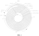
- the inventor has found through research that for an electrochemical device 100' with a wound electrode assembly 20' of a cylindrical structure, during the charge process of the electrochemical device 100', the negative electrode plate 22' may swell due to intercalation of metal ions. Due to a smaller curvature of an inner winding circle, the required radius change for the inner winding circle is larger to reach a same volume expansion. However, the radius change of the inner winding circle is restricted, forming inward radial pressure, which over time easily leads to the collapse of the electrode plate in the inner winding circle, affecting the service life of the electrochemical device 100'.
- the wound electrode assembly 20' has a spiral involute structure, its diameter at the positive electrode winding ending end 2112' is the largest, and the inward radial pressure is also the greatest. Additionally, when the housing 10' is also of a cylindrical structure, with the progression of cycling and the swelling of the electrode assembly 20', a first position A where an outermost side of the electrode assembly 20' corresponds to the positive electrode winding ending end 2112' and a second position B on a same radial line as the first position A will first come into contact with an inner wall of the housing 10'.
- the housing 10' further applies radial compressive force pointing to the winding centerline F1 at the first position A and the second position B, gradually transforming a circular winding central hole 24 (that is, the winding central hole before deformation 24a in FIG. 1 ) of the electrode assembly into an elliptical winding central hole 24 (that is, the winding central hole 24b after deformation in FIG. 1 ).
- the minor axis of the elliptical winding central hole 24b lies on a line connecting the first position A and the second position B
- the major axis of the elliptical winding central hole 24b lies on a line connecting the third position C and the fourth position D.
- the electrochemical device 100 includes a housing 10 and a wound electrode assembly 20. An accommodating space is formed inside the housing 10.
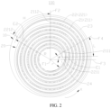
- the wound electrode assembly 20 is accommodated in the accommodating space, where the wound electrode assembly 20 has a winding centerline F1, the wound electrode assembly 20 includes a positive electrode plate 21 and a negative electrode plate 22, the positive electrode plate 21 includes a positive electrode active material layer 211, and along a winding direction X of the positive electrode plate 21, the positive electrode active material layer 211 has a positive electrode winding starting end 2111 and a positive electrode winding ending end 2112; where when observed along a direction of the winding centerline F1, a straight line passing through the positive electrode winding ending end 2112 and orthogonal to the winding centerline F1 is defined as a first reference line F2, a straight line orthogonal to the first reference line F2 and orthogonal to the winding centerline F1 is defined as a second reference line F3, and a straight line passing through the positive electrode winding starting end 2111 and orthogonal to the winding centerline F1 is defined as a third reference line F4, where a zero or acute angle ⁇ exists between the third reference line F4 and the
- the positive electrode winding starting end 2111 of the positive electrode active material layer 211 is disposed close to the second reference line F3.
- the second reference line F3 is near a major axis of the elliptical winding central hole after deformation, and endpoints of the major axis of the elliptical winding central hole have a smaller curvature, being able to withstand greater pressure, the collapse failure of the electrode plate winding starting end is inhibited.
- the positive electrode winding starting end 2111 being near the major axis endpoints of the elliptical winding central hole after deformation can provide good arch support, allowing the electrode plate in an inner winding circle to withstand greater radial pressure along the first reference line F2, thereby inhibiting the collapse of the electrode plate in the inner winding circle. This reduces the risk of electrochemical device 100 failure due to the collapse of the electrode plate in the inner winding circle, thereby improving the service life of the electrochemical device 100.
- the housing 10 may be cylindrical, and an axis of the housing 10 may be parallel to the winding centerline F1 of the wound electrode assembly 20. In some cases, the axis of the housing 10 and the winding centerline F1 of the electrode assembly may also coincide.
- the electrode assembly 20 further includes a separator 23, and the positive electrode plate 21, the separator 23, and the negative electrode plate 22 are stacked and wound to form the wound electrode assembly 20.
- the separator 23 is used to isolate the positive electrode plate 21 and the negative electrode plate 22.
- the material of the separator 23 may be polypropylene (PP) or polyethylene (PE), and the like.
- the electrochemical device 100 mainly relies on movement of metal ions between the positive electrode plate 21 and the negative electrode plate 22 to work.
- the positive electrode plate 21 includes a positive electrode active material layer 211 and a positive electrode current collector 212.
- the negative electrode plate 22 includes a negative electrode active material layer 221 and a negative electrode current collector 222.
- the material of the positive electrode current collector 212 may be aluminum, and the positive electrode active material may be lithium cobalt oxide, lithium iron phosphate, lithium nickel cobalt manganese oxide, lithium nickel cobalt aluminum oxide, or lithium manganese oxide, and the like.
- the negative electrode current collector 222 may be made of copper, and the negative electrode active material may be carbon, silicon, or the like.
- two opposite surfaces of the positive electrode current collector 212 may both be provided with the positive electrode active material layer 211.
- two opposite surfaces of the negative electrode current collector 222 may both be provided with the negative electrode active material layer 221.
- the positive electrode winding starting end 2111 refers to an end of the positive electrode active material layer 211 closest to the winding centerline F1 along the winding direction X.
- the positive electrode winding ending end 2112 refers to an end of the positive electrode plate 21 furthest from the winding centerline F1 along the winding direction X.
- the positive electrode winding ending ends 2112 of the positive electrode active material layers 211 on two surfaces of the positive electrode current collector 212 of the positive electrode plate 21 in the thickness direction of positive electrode current collector 212 may be flush, in which case the first reference line F2 may be a straight line passing through the positive electrode winding ending end 2112 of either of the two positive electrode active material layers 211 and orthogonal to the winding centerline F1.
- the positive electrode winding ending ends 2112 of the positive electrode active material layers 211 on two surfaces of the positive electrode current collector 212 of the positive electrode plate 21 in the thickness direction of the positive electrode current collector 212 may not be flush, that is, along the winding direction X, the positive electrode winding ending end 2112 of one of the two positive electrode active material layers 211 extends beyond the positive electrode winding ending end 2112 of the other positive electrode active material layer, or it can be understood that along the winding direction X, the positive electrode winding ending end 2112 of one of the two positive electrode active material layers 211 is located in front of the positive electrode winding ending end 2112 of the other positive electrode active material layer 211.
- the first reference line F2 is a straight line passing through the positive electrode winding ending end 2112 located at the rear (closer to the positive electrode winding starting end 2111) in the winding direction X and orthogonal to the winding centerline F1.
- the positive electrode winding starting ends 2111 of the positive electrode active material layers 211 on two surfaces of the positive electrode current collector 212 of the positive electrode plate 21 in the thickness direction of positive electrode current collector 212 may be flush, in which case the third reference line F4 may be a straight line passing through the positive electrode winding starting end 2111 of either of the two positive electrode active material layers 211 and orthogonal to the winding centerline F1.
- the positive electrode winding starting ends 2111 of the positive electrode active material layers 211 on two surfaces of the positive electrode current collector 212 of the positive electrode plate 21 in the thickness direction of the positive electrode current collector 212 may not be flush, that is, along a direction opposite the winding direction X, the positive electrode winding starting end 2111 of one of the two positive electrode active material layers 211 extends beyond the positive electrode winding starting end 2111 of the other positive electrode active material layer, or it can be understood that along the direction opposite the winding direction X, the positive electrode winding starting end 2111 of one of the two positive electrode active material layers 211 is located in front of the positive electrode winding starting end 2111 of the other positive electrode active material layer 211.
- the third reference line F4 is a straight line passing through the positive electrode winding starting end 2111 located at the rear in the direction opposite the winding direction X and orthogonal to the winding centerline F1.
- the first reference line F2 may be understood as a line passing through the positive electrode winding ending end 2112 and perpendicular to the winding centerline F1.
- the second reference line F3 may be understood as a line perpendicular to the first reference line F2 and the winding centerline F1.
- the third reference line F4 may be understood as a line passing through the positive electrode winding starting end 2111 and perpendicular to the winding centerline F1.
- Table 1 shows the results of cyclic testing verification for a cylindrical steel housing lithium-ion battery, in which the positive electrode material of the lithium-ion battery is LiNi0.5Co0.2Mn0.3O2, the negative electrode material is graphite, and a radius R of the wound electrode assembly is 5.5mm.
- Step A The battery was charged at a constant current with a constant rate of 2C. When the voltage reached the charging limit voltage of 4.2V, the battery was charged at a constant voltage of 4.2V until the charging current reached a cutoff current of 0.05C. The battery was then left for standing for 5 minutes.
- Step B The battery was discharged at a constant current of 10C until a termination voltage of 2.8V was reached. Step A and Step B were repeated for 300 charge-discharge cycles. Afterward, a CT scanning test is performed to evaluate the collapse conditions of the electrode plates.
- the degree of collapse is distinguished as follows: Taking the winding centerline F1 as the reference and the initial radius of the winding central hole 24 was denoted as r. After cycling, if the shortest distance from the electrode plate to the winding centerline F1 is 0.9r-r, it means no collapse; and if collapse occurs after cycling, and the shortest distance from the collapsed electrode plate to the winding centerline F1 is denoted as a, when 0.7r ⁇ a ⁇ 0.9r, it means slight collapse; when 0.5r ⁇ a ⁇ 0.7r, it means moderate collapse; and when 0 ⁇ a ⁇ 0.5r, it means severe collapse.
- the first end and the second end in Table 1 are the respectively two opposite intersections of the second reference line F3 with the wound electrode assembly 20.
- the third reference line F4 may be on a side of the second reference line F3 in the winding direction X, or on another side of the second reference line F3 in the direction opposite the winding direction X, that is, ⁇ may be a positive angle or a negative angle, meaning the third reference line F4 may deviate a certain angle value relative to the second reference line F3 in the winding direction X or the direction opposite the winding direction X.
- + ⁇ and - ⁇ are used for distinction.
- ⁇ may be 5°, 8°, 11°, 13°, 15°, 18°, and the like.
- the positive electrode winding starting end 2111 of the positive electrode active material layer 211 is disposed closer to the second reference line F3.
- this can better inhibit the collapse failure of the electrode plate winding starting end, and on the other hand, this can better support the electrode plate in an inner winding circle, further inhibiting the collapse of the electrode plate in the inner winding circle, thereby improving the service life of the electrochemical device 100.
- the wound electrode assembly 20 has a winding central hole 24, a radius of the winding central hole 24 is r, and a radius of the wound electrode assembly 20 is R, satisfying r ⁇ 0.15R.
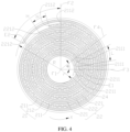
- the radius r of the winding central hole 24 may be equivalent to a radius of a circle with a circumference equal to a length of the electrode plate in the innermost circle and centered on the winding centerline F1.
- the length of the electrode plate in the innermost circle refers to the length of the segment from the starting end of the electrode plate in the innermost circle along the winding direction X to the first alignment of this starting end.
- the length of the electrode plate in the innermost circle is a length of a segment from the negative electrode winding starting end 2211 of the negative electrode plate 22 along the winding direction X to the position where the negative electrode winding starting end 2211 is aligned for the first time in the radial direction of the wound electrode assembly 20 (the fifth position E1 in the figure).
- the radius R of the wound electrode assembly 20 may be equivalent to a radius of a circle with a circumference equal to a length of the electrode plate in the outermost circle and centered on the winding centerline F1.
- the length of the electrode plate in the outermost circle refers to a length of a segment from the ending end of the electrode plate in the outermost circle along the direction opposite the winding direction X to a first alignment of this ending end in the radial direction of the wound electrode assembly 20 (the sixth position E2 in the figure).
- the radius R of the wound electrode assembly 20 and the radius r of the winding central hole 24 of the wound electrode assembly 20 satisfying r ⁇ 0.15R enables the winding central hole 24 to have enough space, and when an inner winding circle of the wound electrode assembly 20 is subjected to radial pressure, enough buffer space exists to provide a certain buffer, thereby further alleviating the collapse of the electrode plates in the inner winding circle.
- r ⁇ 0.3R As shown in Table 1, when r is 0.3R, 0.4R, 0.5R, and 0.6R, the electrode plates are almost not collapsed.
- r ⁇ 0.5R As can be seen from Table 1, when r is 0.6R, although the electrode plates are almost not collapsed, the space of the winding central hole 24 is too large, occupying a large internal space of the housing 10, resulting in a lower energy density of the electrochemical device 100.
- r may be 0.45R, 0.35R, 0.25R, 0.18R, and the like.
- r ⁇ 1mm In some embodiments, r ⁇ 1mm.
- r may be 2mm, 3mm, 4mm, 5mm, and the like.
- the winding central hole 24 has enough space, and the risk of collapse of the electrode plates in an inner winding circle is low. This is conducive to sufficient infiltration of the electrolyte into the wound electrode assembly 20, thereby helping to fully utilize the capacity of the active material.
- the negative electrode plate 22 includes a negative electrode active material layer 221, the negative electrode active material layer 221 has a negative electrode winding ending end 2212, and along a winding direction X of the wound electrode assembly 20, the negative electrode winding ending end 2212 extends beyond the positive electrode winding ending end 2112.
- the negative electrode winding ending end 2212 refers to the end of the negative electrode active material layer 221 furthest from the winding centerline F1 along the winding direction X, specifically the end of the negative electrode active material layer 221 furthest from the winding center along the winding direction X.
- the negative electrode winding ending end 2212 of each negative electrode active material layer 221 can extend only along the winding direction X beyond the positive electrode winding ending end 2112 of the positive electrode active material layer 211 provided opposite the negative electrode active material layer 221 with the separator 23 in between.
- the negative electrode winding ending end 2212 of the negative electrode active material layer 221 extending beyond the positive electrode winding ending end 2112 of the positive electrode active material layer 211 is conducive to the positive electrode active material layer 211 being fully covered by the negative electrode active material layer 221, reducing the risk of lithium precipitation in the electrochemical device 100.
- a length by which the negative electrode winding ending end 2212 extends beyond the positive electrode winding ending end 2112 is greater than or equal to 1mm.
- the length by which the negative electrode winding ending end 2212 of the negative electrode active material layer 221 extends along the winding direction X beyond the positive electrode winding ending end 2112 of the positive electrode active material layer 211 provided opposite and facing the negative electrode active material layer 221 is greater than or equal to 1mm. That is, the distance H in the winding direction X between the negative electrode winding ending end 2212 of the negative electrode active material layer 221 and the positive electrode winding ending end 2112 of the positive electrode active material layer 211 provided opposite the negative electrode active material layer 221 with the separator 23 in between satisfies H ⁇ 1mm. H may be 2mm, 3mm, 4mm, 5mm, and the like.
- the length by which the negative electrode winding ending end 2212 extends beyond the positive electrode winding ending end 2112 being greater than or equal to 1mm is conducive to the positive electrode active material layer 211 being fully covered by the negative electrode active material layer 221, reducing the risk of lithium precipitation in the electrochemical device 100.
- the negative electrode winding ending end 2212 may also be flush with the positive electrode winding ending end 2112.
- the negative electrode winding starting end 2211 is located on an inner side of the positive electrode winding starting end 2111, that is, along the radial direction of the wound electrode assembly 20, a distance between the negative electrode winding starting end 2211 and the winding centerline F1 is less than a distance between the positive electrode winding starting end 2111 and the winding centerline F1.
- the negative electrode winding starting end 2211 refers to an end of the negative electrode active material layer 221 closest to the winding centerline F1 along the winding direction X.
- the negative electrode winding starting end 2211 of each negative electrode active material layer 221 can extend only along the direction opposite the winding direction X beyond the positive electrode winding starting end 2111 of the positive electrode active material layer 211 provided opposite the negative electrode active material layer 221 with the separator 23 in between.
- the negative electrode winding starting end 2211 of the negative electrode active material layer 221 extending beyond the positive electrode winding starting end 2111 of the positive electrode active material layer 211 is conducive to the positive electrode active material layer 211 being fully covered by the negative electrode active material layer 221, reducing the risk of lithium precipitation in the electrochemical device 100.
- the length by which the negative electrode winding starting end 2211 extends beyond the positive electrode winding starting end 2111 is greater than or equal to 1mm.
- the length by which the negative electrode winding starting end 2211 of the negative electrode active material layer 221 extends along the direction opposite the winding direction X beyond the positive electrode winding starting end 2111 of the positive electrode active material layer 211 provided opposite and facing the negative electrode active material layer 221 is greater than or equal to 1mm. That is, the distance L in the direction opposite the winding direction X between the negative electrode winding starting end 2211 of the negative electrode active material layer 221 and the positive electrode winding starting end 2111 of the positive electrode active material layer 211 provided opposite the negative electrode active material layer 221 with the separator 23 in between satisfies L ⁇ 1mm. L may be 2mm, 3mm, 4mm, 5mm, and the like.
- the length by which the negative electrode winding starting end 2211 extends beyond the positive electrode winding starting end 2111 being greater than or equal to 1mm is conducive to the positive electrode active material layer 211 being fully covered by the negative electrode active material layer 221, reducing the risk of lithium precipitation in the electrochemical device 100.
- the negative electrode winding starting end 2211 may also be flush with the positive electrode winding starting end 2111.
- an outermost circle electrode plate of the wound electrode assembly 20 is the negative electrode plate 22, and/or an innermost circle electrode plate of the wound electrode assembly 20 is the negative electrode plate 22. It may be that the outermost circle electrode plate of the wound electrode assembly 20 is the negative electrode plate 22, and the innermost circle electrode plate of the wound electrode assembly 20 is the positive electrode plate 21; or it may be that the outermost circle electrode plate of the wound electrode assembly 20 is the positive electrode plate 21, and the innermost circle electrode plate of the wound electrode assembly 20 is the negative electrode plate 22; or it may be that both the outermost circle electrode plate and the innermost circle electrode plate of the wound electrode assembly 20 are the negative electrode plates 22.
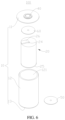
- the housing 10 includes a cover 11, a side wall 12, and a bottom wall 13, the side wall 12 being cylindrical, and the electrochemical device 100 further includes an electrode terminal 40 and a positive electrode current collecting member 50, the wound electrode assembly 20 includes a positive electrode tab 25, and the electrode terminal 40 is disposed on the cover 11 and is electrically connected to the positive electrode tab 25 through the positive electrode current collecting member 50.
- the positive electrode tab 25 is electrically connected to the positive electrode current collector 212 of the positive electrode plate 21.
- the positive electrode tab 25 protrudes from one side of the positive electrode plate 21 along an extension direction of the winding centerline F1, and the extension direction of the winding centerline F1 is consistent with a width direction of the positive electrode plate 21.
- the positive electrode tab 25 and the positive electrode current collector 212 may be provided separately and then connected into an integral structure by welding, bonding, and the like.
- the positive electrode tab 25 and the positive electrode current collector 212 may also be integrally formed.
- the material of the positive electrode tab 25 may be the same as or different from the material of the positive electrode current collector 212.
- the number of positive electrode tabs 25 may be one or multiple. Multiple includes two and more. In this embodiment, the size of the positive electrode tab 25 along the winding direction X is smaller than the size of the positive electrode current collector 212 along the winding direction X.
- the bottom wall 13 is connected to one end of the side wall 12 along its axial direction, and the bottom wall 13 and the side wall 12 may be integrally formed or provided separately and then connected into one piece through welding, bonding, and the like.
- An opening 121 is formed at another end of the side wall 12 along its axial direction opposite the bottom wall 13, and the cover 11 is configured to seal the opening 121 so that the cover 11, the side wall 12, and the bottom wall 13 together form the accommodating space for accommodating the wound electrode assembly 20.
- the electrode terminal 40 may be insulated from and provided on the cover 11.
- the positive electrode current collecting member 50 is a conductive component, and the electrical connection between the positive electrode tab 25 and the electrode terminal 40 is implemented through the positive electrode current collecting member 50.
- the positive electrode current collecting member 50 may be welded or abutted with the positive electrode tab 25.
- the positive electrode current collector 212 may be welded or abutted with the electrode terminal 40.
- the negative electrode plate 22 may be electrically connected with the side wall 12 or the bottom wall 13.
- the electrode terminal 40 and the positive electrode tab 25 being electrically connected through the positive electrode current collecting member 50 is conducive to improving the stability of the electrical connection between the electrode terminal 40 and the positive electrode tab 25.
- the electrochemical device 100 further includes a negative electrode current collecting member 60
- the wound electrode assembly 20 includes a negative electrode tab 26
- the bottom wall 13 is electrically connected to the negative electrode tab 26 through the negative electrode current collecting member 60.
- the negative electrode tab 26 is electrically connected to the negative electrode current collector 222 of the negative electrode plate 22.
- the negative electrode tab 26 protrudes from one side of the negative electrode plate 22 along an extension direction of the winding centerline F1, and the extension direction of the winding centerline F1 is consistent with a width direction of the negative electrode plate 22.
- the negative electrode tab 26 and the negative electrode current collector 222 may be provided separately and then connected into an integral structure by welding, bonding, and the like.
- the negative electrode tab 26 and the negative electrode current collector 222 may also be integrally formed.
- the material of the negative electrode tab 26 may be the same as or different from the material of the negative electrode current collector 222.
- the number of negative electrode tabs 26 may be one or multiple. In this embodiment, the size of the negative electrode tab 26 along the winding direction X is smaller than the size of the negative electrode current collector 222 along the winding direction X.
- the positive electrode tab 25 and the negative electrode tab 26 are respectively located at two ends of the wound electrode assembly 20 in the winding centerline F1.
- the negative electrode current collecting member 60 may be welded or abutted with the negative electrode tab 26.
- the negative electrode current collecting member 60 may be welded or abutted with the bottom wall 13.
- the bottom wall 13 and the negative electrode tab 26 being electrically connected through the negative electrode current collecting member 60 is conducive to improving the stability of the electrical connection between the negative electrode terminal and the negative electrode tab 26.
- the positive electrode tab 25 may be electrically connected to the bottom wall 13 through the positive electrode current collecting member 50, and the negative electrode tab 26 may be electrically connected to the electrode terminal 40 through the negative electrode current collecting member 60.
- the housing 10 includes a cover 11, a side wall 12, and a bottom wall 13, the side wall 12 being cylindrical, and the electrochemical device 100 further includes an electrode terminal 40 and a positive electrode current collecting member 50.
- the positive electrode plate 21 further includes a positive electrode current collector 212, and the positive electrode current collector 212 includes a positive electrode coating region 2121 and a positive electrode tab region 2122, the positive electrode tab region 2122 being located at one end in a width direction of the positive electrode current collector 212, where the positive electrode active material layer 211 is disposed on a surface of the positive electrode coating region 2121, the positive electrode tab region 2122 is bent toward the winding centerline F1 to form a first end surface 2123 of the wound electrode assembly 20, and the electrode terminal 40 is disposed on the cover 11 and is electrically connected to the first end surface 2123 through the positive electrode current collecting member 50.
- the width direction of the positive electrode current collector 212 is parallel to the width direction of the positive electrode plate 21.
- the positive electrode tab region 2122 is a region on one side of the positive electrode current collector 212 along its width direction that is not coated with the positive electrode active material layer 211.
- a dimension of the positive electrode tab region 2122 along a length direction of the positive electrode plate 21 is the same as a dimension of the positive electrode coating region 2121 along a length direction of the positive electrode plate 21.
- the length direction of the positive electrode plate 21 is consistent with the winding direction X.
- the positive electrode tab region 2122 is bent toward the winding centerline F1 through a flattening method, forming a relatively flat first end surface 2123.
- the positive electrode current collecting member 50 may be welded or abutted with the first end surface 2123.
- the electrode terminal 40 is disposed on the cover 11 and connected to the first end surface 2123 through the positive electrode current collecting member 50, which is conducive to increasing the connection area between the positive electrode current collecting member 50 and the positive electrode plate 21, thereby improving the rate performance of the electrochemical device 100.
- the electrochemical device 100 further includes a negative electrode current collecting member 60
- the negative electrode plate 22 further includes a negative electrode current collector 222
- the negative electrode current collector 222 includes a negative electrode coating region 2221 and a negative electrode tab region 2222, the negative electrode tab region 2222 being located at one end in a width direction of the negative electrode current collector 222, where the negative electrode active material layer 221 is disposed on a surface of the negative electrode coating region 2221, the negative electrode tab region 2222 is bent toward the winding centerline F1 to form a second end surface 2223 of the wound electrode assembly 20, and the bottom wall 13 is connected to the second end surface 2223 through the negative electrode current collecting member 60.
- the width direction of the negative electrode current collector 222 is parallel to the width direction of the negative electrode plate 22.
- the negative electrode tab region 2222 is a region on one side of the negative electrode current collector 222 along its width direction that is not coated with the negative electrode active material layer 221.
- a dimension of the negative electrode tab region 2222 along a length direction of the negative electrode plate 22 is the same as a dimension of the negative electrode coating region 2221 along a length direction of the negative electrode plate 22.
- the length direction of the negative electrode plate 22 is consistent with the winding direction X.
- the negative electrode tab region 2222 is bent toward the winding centerline F1 through a flattening method, forming a relatively flat second end surface 2223.
- the first end surface 2123 and the second end surface 2223 are respectively located at two ends of the wound electrode assembly 20 in the extension direction of the winding centerline F1.
- the negative electrode current collecting member 60 may be welded or abutted with the second end surface 2223.
- the bottom wall 13 being connected to the second end surface 2223 through the negative electrode current collecting member 60 is conducive to increasing the connection area between the negative electrode current collecting member 60 and the negative electrode plate 22, thereby improving the rate performance of the electrochemical device 100.
- the first end surface 2123 may be electrically connected to the bottom wall 13 through the positive electrode current collecting member 50, and the second end surface 2223 may be electrically connected to the electrode terminal through the negative electrode current collecting member 60.
- the wound electrode assembly 20 includes a negative electrode tab 26, where the negative electrode tab 26 is electrically connected to the negative electrode current collector 222 of the negative electrode plate 22, and the negative electrode tab 26 is electrically connected to the electrode terminal 40 through the negative electrode current collector 222.
- the positive electrode plate 21 includes a positive electrode current collector 212, and the positive electrode current collector 212 includes a positive electrode coating region 2121 and a positive electrode tab region 2122, the positive electrode tab region 2122 being located at one end in a width direction of the positive electrode current collector 212, where the positive electrode active material layer 211 is disposed on a surface of the positive electrode coating region 2121, the positive electrode tab region 2122 is bent toward the winding centerline F1 to form a first end surface 2123 of the wound electrode assembly 20.
- the first end surface 2123 and the negative electrode tab 26 are arranged opposite each other along the extension direction of the winding centerline F1.
- the bottom wall 13 is connected to the first end surface 2123 through the positive electrode current collecting member 50.
- the wound electrode assembly 20 includes a positive electrode tab 25.
- the positive electrode tab 25 is electrically connected to the positive electrode current collector 212 of the positive electrode plate 21.
- the positive electrode tab 25 is electrically connected to the electrode terminal 40 through the positive electrode current collector 212.
- the negative electrode plate 22 includes a negative electrode current collector 222.
- the negative electrode current collector 222 includes a negative electrode coating region 2221 and a negative electrode tab region 2222.
- the negative electrode tab region 2222 is located at one end in the width direction of the negative electrode current collector 222.
- the negative electrode active material layer 221 is disposed on the surface of the negative electrode coating region 2221, and the negative electrode tab region 2222 is bent toward the winding centerline F1 to form the second end surface 2223 of the wound electrode assembly 20.
- the positive electrode tab 25 and the second end surface 2223 are arranged opposite each other along the extension direction of the winding centerline F1.
- the bottom wall 13 is connected to the second end surface 2223 through the negative electrode current collecting member 60.
- the embodiments of this application further provide an electric device, including the electrochemical device 100 provided in any of the foregoing embodiments.
- the electric device further includes an electricity-consuming body, and the electrochemical device 100 provides electrical energy to the electricity-consuming body.
- the electric device may include, but is not limited to, electronic devices, electric tools, electric transportation tools, drones, and energy storage devices.
- the electronic device may include a mobile phone, a tablet computer, a notebook computer, or the like
- the electric tool may include an electric drill, an electric saw, or the like
- the electric transportation tool may include an electric vehicle, an electric motorcycle, an electric bicycle, or the like.
Landscapes
- Chemical & Material Sciences (AREA)
- Chemical Kinetics & Catalysis (AREA)
- Electrochemistry (AREA)
- General Chemical & Material Sciences (AREA)
- Engineering & Computer Science (AREA)
- Manufacturing & Machinery (AREA)
- Secondary Cells (AREA)
- Materials Engineering (AREA)
- Primary Cells (AREA)
Applications Claiming Priority (1)
| Application Number | Priority Date | Filing Date | Title |
|---|---|---|---|
| PCT/CN2022/115878 WO2024044973A1 (zh) | 2022-08-30 | 2022-08-30 | 电化学装置及用电设备 |
Publications (2)
| Publication Number | Publication Date |
|---|---|
| EP4576298A1 true EP4576298A1 (de) | 2025-06-25 |
| EP4576298A4 EP4576298A4 (de) | 2025-10-29 |
Family
ID=88046475
Family Applications (1)
| Application Number | Title | Priority Date | Filing Date |
|---|---|---|---|
| EP22956805.0A Pending EP4576298A4 (de) | 2022-08-30 | 2022-08-30 | Elektrochemische vorrichtung und elektrische vorrichtung |
Country Status (6)
| Country | Link |
|---|---|
| US (1) | US20250167309A1 (de) |
| EP (1) | EP4576298A4 (de) |
| JP (1) | JP2025528216A (de) |
| KR (1) | KR20240163756A (de) |
| CN (1) | CN116802864A (de) |
| WO (1) | WO2024044973A1 (de) |
Families Citing this family (2)
| Publication number | Priority date | Publication date | Assignee | Title |
|---|---|---|---|---|
| CN117457965B (zh) * | 2023-12-25 | 2024-04-02 | 天鹏锂能技术(淮安)有限公司 | 一种卷绕电芯 |
| WO2026000305A1 (zh) * | 2024-06-27 | 2026-01-02 | 宁德新能源科技有限公司 | 一种电极组件、电池及用电设备 |
Family Cites Families (15)
| Publication number | Priority date | Publication date | Assignee | Title |
|---|---|---|---|---|
| JPH06223841A (ja) * | 1992-11-25 | 1994-08-12 | Hitachi Maxell Ltd | 電池用渦巻式電極体 |
| JP4866496B2 (ja) * | 1999-04-08 | 2012-02-01 | パナソニック株式会社 | 二次電池の製造方法 |
| JP2003297432A (ja) * | 2002-04-04 | 2003-10-17 | Sony Corp | 非水電解質二次電池 |
| JP2003303624A (ja) * | 2002-04-11 | 2003-10-24 | Sony Corp | 非水電解質二次電池 |
| JP2004063410A (ja) * | 2002-07-31 | 2004-02-26 | Sony Corp | 密閉型非水電解液電池 |
| CN101960649A (zh) * | 2008-03-07 | 2011-01-26 | 松下电器产业株式会社 | 锂离子二次电池及其制造方法 |
| JP5974853B2 (ja) * | 2012-11-23 | 2016-08-23 | トヨタ自動車株式会社 | 電池の製造方法 |
| CN112236894A (zh) * | 2018-06-20 | 2021-01-15 | 三洋电机株式会社 | 非水电解质二次电池 |
| CN208970673U (zh) * | 2018-08-31 | 2019-06-11 | 深圳市比克动力电池有限公司 | 锂离子电池及其卷芯 |
| JP7320738B2 (ja) * | 2018-10-26 | 2023-08-04 | パナソニックIpマネジメント株式会社 | 円筒型二次電池 |
| JP7153193B2 (ja) * | 2018-12-11 | 2022-10-14 | トヨタ自動車株式会社 | 非水電解液二次電池 |
| CN214706178U (zh) * | 2021-03-26 | 2021-11-12 | 比亚迪股份有限公司 | 纽扣电池 |
| CN216450704U (zh) * | 2021-12-13 | 2022-05-06 | 宁德时代新能源科技股份有限公司 | 电极组件、电池单体、电池及用电设备 |
| CN114420994A (zh) * | 2021-12-31 | 2022-04-29 | 曙鹏科技(深圳)有限公司 | 一种软包纽扣电池及其制作方法、电子设备 |
| CN217158235U (zh) * | 2022-03-24 | 2022-08-09 | 宁德时代新能源科技股份有限公司 | 极片、电极组件及其制造装置、电池单体、电池和用电装置 |
-
2022
- 2022-08-30 EP EP22956805.0A patent/EP4576298A4/de active Pending
- 2022-08-30 KR KR1020247036557A patent/KR20240163756A/ko active Pending
- 2022-08-30 WO PCT/CN2022/115878 patent/WO2024044973A1/zh not_active Ceased
- 2022-08-30 JP JP2025508926A patent/JP2025528216A/ja active Pending
- 2022-08-30 CN CN202280010307.2A patent/CN116802864A/zh active Pending
-
2025
- 2025-01-17 US US19/029,044 patent/US20250167309A1/en active Pending
Also Published As
| Publication number | Publication date |
|---|---|
| EP4576298A4 (de) | 2025-10-29 |
| JP2025528216A (ja) | 2025-08-26 |
| CN116802864A (zh) | 2023-09-22 |
| KR20240163756A (ko) | 2024-11-19 |
| US20250167309A1 (en) | 2025-05-22 |
| WO2024044973A1 (zh) | 2024-03-07 |
Similar Documents
| Publication | Publication Date | Title |
|---|---|---|
| US20250167309A1 (en) | Electrochemical device and electric device | |
| US7364817B2 (en) | Secondary battery and method of manufacturing the same | |
| US20220223984A1 (en) | Rechargeable battery | |
| US20080026291A1 (en) | Rechargeable battery | |
| EP4535523A1 (de) | Batterie, herstellungsverfahren dafür, batteriemodul und elektrische vorrichtung | |
| EP4131511A1 (de) | Zelle, batterie und elektronische vorrichtung | |
| EP4579778A1 (de) | Zylindrische batteriezelle und zylindrische sekundärbatterie | |
| EP3926751A1 (de) | Stromabnehmerelement und herstellungsverfahren dafür, sekundärbatterie und herstellungsverfahren dafür, batteriemodul und vorrichtung | |
| CN1292155A (zh) | 使用带有凹口表面的棱柱形外壳的锂离子电池 | |
| JP2025010464A (ja) | 円筒型電池セル、電池アセンブリ及び電子機器 | |
| CN101295773A (zh) | 可再充电电池 | |
| CN119542665A (zh) | 圆柱形二次电池 | |
| EP4489210A1 (de) | Zylindrische sekundärbatterie mit nichtwässrigem elektrolyten | |
| WO2022126414A1 (zh) | 电池及具有所述电池的电子装置 | |
| JP2018049708A (ja) | 蓄電装置及び蓄電装置の製造方法 | |
| EP2309571A1 (de) | Sekundärbatterie | |
| US7794872B2 (en) | Secondary battery | |
| JPH1126023A (ja) | 円筒形電池 | |
| CN222953142U (zh) | 二次电池、电池组及电子装置 | |
| CN223347969U (zh) | 二次电池、电池组及电子装置 | |
| CN222953317U (zh) | 二次电池、电池组及电子装置 | |
| US20250392018A1 (en) | Battery assembly and battery cell including the same | |
| CN222953143U (zh) | 二次电池、电池组及电子装置 | |
| CN222980558U (zh) | 二次电池、电池组和电子装置 | |
| CN223956594U (zh) | 二次电池、电池组及电子装置 |
Legal Events
| Date | Code | Title | Description |
|---|---|---|---|
| STAA | Information on the status of an ep patent application or granted ep patent |
Free format text: STATUS: THE INTERNATIONAL PUBLICATION HAS BEEN MADE |
|
| PUAI | Public reference made under article 153(3) epc to a published international application that has entered the european phase |
Free format text: ORIGINAL CODE: 0009012 |
|
| STAA | Information on the status of an ep patent application or granted ep patent |
Free format text: STATUS: REQUEST FOR EXAMINATION WAS MADE |
|
| 17P | Request for examination filed |
Effective date: 20250318 |
|
| AK | Designated contracting states |
Kind code of ref document: A1 Designated state(s): AL AT BE BG CH CY CZ DE DK EE ES FI FR GB GR HR HU IE IS IT LI LT LU LV MC MK MT NL NO PL PT RO RS SE SI SK SM TR |
|
| A4 | Supplementary search report drawn up and despatched |
Effective date: 20250925 |
|
| RIC1 | Information provided on ipc code assigned before grant |
Ipc: H01M 10/052 20100101AFI20250919BHEP Ipc: H01M 10/058 20100101ALI20250919BHEP Ipc: H01M 50/538 20210101ALI20250919BHEP Ipc: H01M 50/531 20210101ALI20250919BHEP Ipc: H01M 10/0587 20100101ALI20250919BHEP Ipc: H01M 10/0525 20100101ALI20250919BHEP Ipc: H01M 10/04 20060101ALI20250919BHEP |
|
| DAV | Request for validation of the european patent (deleted) | ||
| DAX | Request for extension of the european patent (deleted) |