EP4576336A1 - Module de batterie, bloc-batterie et véhicule - Google Patents
Module de batterie, bloc-batterie et véhicule Download PDFInfo
- Publication number
- EP4576336A1 EP4576336A1 EP23218591.8A EP23218591A EP4576336A1 EP 4576336 A1 EP4576336 A1 EP 4576336A1 EP 23218591 A EP23218591 A EP 23218591A EP 4576336 A1 EP4576336 A1 EP 4576336A1
- Authority
- EP
- European Patent Office
- Prior art keywords
- battery module
- separate
- battery
- members
- longitudinally extending
- Prior art date
- Legal status (The legal status is an assumption and is not a legal conclusion. Google has not performed a legal analysis and makes no representation as to the accuracy of the status listed.)
- Pending
Links
Images


Classifications
-
- H—ELECTRICITY
- H01—ELECTRIC ELEMENTS
- H01M—PROCESSES OR MEANS, e.g. BATTERIES, FOR THE DIRECT CONVERSION OF CHEMICAL ENERGY INTO ELECTRICAL ENERGY
- H01M10/00—Secondary cells; Manufacture thereof
- H01M10/60—Heating or cooling; Temperature control
- H01M10/65—Means for temperature control structurally associated with the cells
- H01M10/655—Solid structures for heat exchange or heat conduction
- H01M10/6554—Rods or plates
-
- H—ELECTRICITY
- H01—ELECTRIC ELEMENTS
- H01M—PROCESSES OR MEANS, e.g. BATTERIES, FOR THE DIRECT CONVERSION OF CHEMICAL ENERGY INTO ELECTRICAL ENERGY
- H01M50/00—Constructional details or processes of manufacture of the non-active parts of electrochemical cells other than fuel cells, e.g. hybrid cells
- H01M50/20—Mountings; Secondary casings or frames; Racks, modules or packs; Suspension devices; Shock absorbers; Transport or carrying devices; Holders
- H01M50/233—Mountings; Secondary casings or frames; Racks, modules or packs; Suspension devices; Shock absorbers; Transport or carrying devices; Holders characterised by physical properties of casings or racks, e.g. dimensions
- H01M50/242—Mountings; Secondary casings or frames; Racks, modules or packs; Suspension devices; Shock absorbers; Transport or carrying devices; Holders characterised by physical properties of casings or racks, e.g. dimensions adapted for protecting batteries against vibrations, collision impact or swelling
-
- B—PERFORMING OPERATIONS; TRANSPORTING
- B60—VEHICLES IN GENERAL
- B60L—PROPULSION OF ELECTRICALLY-PROPELLED VEHICLES; SUPPLYING ELECTRIC POWER FOR AUXILIARY EQUIPMENT OF ELECTRICALLY-PROPELLED VEHICLES; ELECTRODYNAMIC BRAKE SYSTEMS FOR VEHICLES IN GENERAL; MAGNETIC SUSPENSION OR LEVITATION FOR VEHICLES; MONITORING OPERATING VARIABLES OF ELECTRICALLY-PROPELLED VEHICLES; ELECTRIC SAFETY DEVICES FOR ELECTRICALLY-PROPELLED VEHICLES
- B60L50/00—Electric propulsion with power supplied within the vehicle
- B60L50/50—Electric propulsion with power supplied within the vehicle using propulsion power supplied by batteries or fuel cells
- B60L50/60—Electric propulsion with power supplied within the vehicle using propulsion power supplied by batteries or fuel cells using power supplied by batteries
- B60L50/64—Constructional details of batteries specially adapted for electric vehicles
-
- H—ELECTRICITY
- H01—ELECTRIC ELEMENTS
- H01M—PROCESSES OR MEANS, e.g. BATTERIES, FOR THE DIRECT CONVERSION OF CHEMICAL ENERGY INTO ELECTRICAL ENERGY
- H01M10/00—Secondary cells; Manufacture thereof
- H01M10/60—Heating or cooling; Temperature control
- H01M10/61—Types of temperature control
- H01M10/613—Cooling or keeping cold
-
- H—ELECTRICITY
- H01—ELECTRIC ELEMENTS
- H01M—PROCESSES OR MEANS, e.g. BATTERIES, FOR THE DIRECT CONVERSION OF CHEMICAL ENERGY INTO ELECTRICAL ENERGY
- H01M10/00—Secondary cells; Manufacture thereof
- H01M10/60—Heating or cooling; Temperature control
- H01M10/62—Heating or cooling; Temperature control specially adapted for specific applications
- H01M10/625—Vehicles
-
- H—ELECTRICITY
- H01—ELECTRIC ELEMENTS
- H01M—PROCESSES OR MEANS, e.g. BATTERIES, FOR THE DIRECT CONVERSION OF CHEMICAL ENERGY INTO ELECTRICAL ENERGY
- H01M10/00—Secondary cells; Manufacture thereof
- H01M10/60—Heating or cooling; Temperature control
- H01M10/64—Heating or cooling; Temperature control characterised by the shape of the cells
- H01M10/647—Prismatic or flat cells, e.g. pouch cells
-
- H—ELECTRICITY
- H01—ELECTRIC ELEMENTS
- H01M—PROCESSES OR MEANS, e.g. BATTERIES, FOR THE DIRECT CONVERSION OF CHEMICAL ENERGY INTO ELECTRICAL ENERGY
- H01M10/00—Secondary cells; Manufacture thereof
- H01M10/60—Heating or cooling; Temperature control
- H01M10/65—Means for temperature control structurally associated with the cells
- H01M10/655—Solid structures for heat exchange or heat conduction
- H01M10/6556—Solid parts with flow channel passages or pipes for heat exchange
-
- H—ELECTRICITY
- H01—ELECTRIC ELEMENTS
- H01M—PROCESSES OR MEANS, e.g. BATTERIES, FOR THE DIRECT CONVERSION OF CHEMICAL ENERGY INTO ELECTRICAL ENERGY
- H01M50/00—Constructional details or processes of manufacture of the non-active parts of electrochemical cells other than fuel cells, e.g. hybrid cells
- H01M50/20—Mountings; Secondary casings or frames; Racks, modules or packs; Suspension devices; Shock absorbers; Transport or carrying devices; Holders
- H01M50/204—Racks, modules or packs for multiple batteries or multiple cells
- H01M50/207—Racks, modules or packs for multiple batteries or multiple cells characterised by their shape
- H01M50/209—Racks, modules or packs for multiple batteries or multiple cells characterised by their shape adapted for prismatic or rectangular cells
-
- H—ELECTRICITY
- H01—ELECTRIC ELEMENTS
- H01M—PROCESSES OR MEANS, e.g. BATTERIES, FOR THE DIRECT CONVERSION OF CHEMICAL ENERGY INTO ELECTRICAL ENERGY
- H01M50/00—Constructional details or processes of manufacture of the non-active parts of electrochemical cells other than fuel cells, e.g. hybrid cells
- H01M50/20—Mountings; Secondary casings or frames; Racks, modules or packs; Suspension devices; Shock absorbers; Transport or carrying devices; Holders
- H01M50/249—Mountings; Secondary casings or frames; Racks, modules or packs; Suspension devices; Shock absorbers; Transport or carrying devices; Holders specially adapted for aircraft or vehicles, e.g. cars or trains
-
- H—ELECTRICITY
- H01—ELECTRIC ELEMENTS
- H01M—PROCESSES OR MEANS, e.g. BATTERIES, FOR THE DIRECT CONVERSION OF CHEMICAL ENERGY INTO ELECTRICAL ENERGY
- H01M50/00—Constructional details or processes of manufacture of the non-active parts of electrochemical cells other than fuel cells, e.g. hybrid cells
- H01M50/20—Mountings; Secondary casings or frames; Racks, modules or packs; Suspension devices; Shock absorbers; Transport or carrying devices; Holders
- H01M50/262—Mountings; Secondary casings or frames; Racks, modules or packs; Suspension devices; Shock absorbers; Transport or carrying devices; Holders with fastening means, e.g. locks
- H01M50/264—Mountings; Secondary casings or frames; Racks, modules or packs; Suspension devices; Shock absorbers; Transport or carrying devices; Holders with fastening means, e.g. locks for cells or batteries, e.g. straps, tie rods or peripheral frames
-
- H—ELECTRICITY
- H01—ELECTRIC ELEMENTS
- H01M—PROCESSES OR MEANS, e.g. BATTERIES, FOR THE DIRECT CONVERSION OF CHEMICAL ENERGY INTO ELECTRICAL ENERGY
- H01M50/00—Constructional details or processes of manufacture of the non-active parts of electrochemical cells other than fuel cells, e.g. hybrid cells
- H01M50/20—Mountings; Secondary casings or frames; Racks, modules or packs; Suspension devices; Shock absorbers; Transport or carrying devices; Holders
- H01M50/289—Mountings; Secondary casings or frames; Racks, modules or packs; Suspension devices; Shock absorbers; Transport or carrying devices; Holders characterised by spacing elements or positioning means within frames, racks or packs
-
- H—ELECTRICITY
- H01—ELECTRIC ELEMENTS
- H01M—PROCESSES OR MEANS, e.g. BATTERIES, FOR THE DIRECT CONVERSION OF CHEMICAL ENERGY INTO ELECTRICAL ENERGY
- H01M2220/00—Batteries for particular applications
- H01M2220/20—Batteries in motive systems, e.g. vehicle, ship, plane
-
- Y—GENERAL TAGGING OF NEW TECHNOLOGICAL DEVELOPMENTS; GENERAL TAGGING OF CROSS-SECTIONAL TECHNOLOGIES SPANNING OVER SEVERAL SECTIONS OF THE IPC; TECHNICAL SUBJECTS COVERED BY FORMER USPC CROSS-REFERENCE ART COLLECTIONS [XRACs] AND DIGESTS
- Y02—TECHNOLOGIES OR APPLICATIONS FOR MITIGATION OR ADAPTATION AGAINST CLIMATE CHANGE
- Y02E—REDUCTION OF GREENHOUSE GAS [GHG] EMISSIONS, RELATED TO ENERGY GENERATION, TRANSMISSION OR DISTRIBUTION
- Y02E60/00—Enabling technologies; Technologies with a potential or indirect contribution to GHG emissions mitigation
- Y02E60/10—Energy storage using batteries
Definitions
- the disclosure relates generally to energy storage systems.
- the disclosure relates to a battery module, a battery pack, and a vehicle.
- the disclosure can be applied to heavy-duty vehicles, such as trucks, buses, and construction equipment, among other vehicle types.
- heavy-duty vehicles such as trucks, buses, and construction equipment, among other vehicle types.
- trucks, buses, and construction equipment among other vehicle types.
- the disclosure may be described with respect to a particular vehicle, the disclosure is not restricted to any particular vehicle.
- a battery pack typically comprises a plurality of battery cells, i.e., electrochemical battery cells, which are electrically connected in series and/or in parallel.
- the battery pack may comprise one or more separate battery modules, wherein each module comprises a stack of battery cells.
- the battery cells may be prismatic battery cells.
- a battery module for a battery pack has a longitudinal extension in a longitudinal direction, a width extension in a width direction and a height extension in a height direction.
- the battery module comprises:
- the at least one group of stacked prismatic battery cells is a group of stacked prismatic side terminal battery cells which are stacked next to each other in the longitudinal direction with side terminals thereof facing in a first direction corresponding to the width direction and/or in a second direction which is opposite to the first direction.
- a technical benefit may include a favorable position of the terminals, allowing the battery module to be more compact in the height direction. This in turn may be beneficial if e.g. stacking several battery modules on top of each other.
- a prismatic side terminal battery cell as used herein means an electrochemical battery cell comprising a prismatic cell housing and terminals on the cell housing, i.e., electrical connections, which are provided on opposite outer ends of the cell housing, as seen along a longitudinal extension of the battery cell.
- the battery cells of the at least one group of stacked prismatic battery cells are fixed to each other by at least one strap which is wrapped around the group of stacked prismatic battery cells.
- a technical benefit may include a cost-effective and compact way of stacking the battery cells together.
- the at least one strap may be wrapped around an axis which corresponds to the width direction.
- a technical benefit may include improved access to terminals of the plurality of battery cells.
- the cooling plate bottom member is mechanically connected to at least one crossbeam member within the plurality of separate crossbeam members by one or more fasteners and/or by one or more welds distributed along the width direction.
- a technical benefit may include that a risk of deflection of the cooling plate member caused by the load from the battery cells can be mitigated.
- the battery module has a first maximum height and at least one of the first and second separate longitudinally extending beam members has a second maximum height, as measured in the height direction, wherein the second maximum height of the at least one of the first and second separate longitudinally extending beam members is lower than the first maximum height of the battery module.
- a technical benefit may include that the side terminals are more easily accessible from the side of the battery module.
- the at least one of the first and second separate longitudinally extending beam members is provided proximate, such as in abutment with, the cooling plate bottom member.
- a technical benefit may include that a more well-defined receiving space is achieved for the at least one group of stacked prismatic battery cells. This may result in a more robust configuration, and/or facilitated assembly/disassembly of the battery module.
- the at least one of the first and second separate longitudinally extending beam members is attached to a respective corner portion of each crossbeam member within the plurality of crossbeam members.
- a technical benefit may include a more robust configuration.
- the battery module comprises more than one group of the at least one group of stacked prismatic battery cells, wherein the first and second separate longitudinally extending beam members, the plurality of separate crossbeam members and the cooling plate bottom member form a respective receiving space for each group of stacked prismatic battery cells.
- a technical benefit may include a robust configuration for a plurality of prismatic battery cells which is easily scalable in the longitudinal direction.
- At least two of the plurality of separate crossbeam members are identical.
- a technical benefit may include a more cost-effective configuration requiring fewer different parts.
- identical may herein mean that the dimensions of the members are identical, and/or that any holes for fasteners are identical and/or placed at the same corresponding positions.
- An aim of the present disclosure is to provide a space-efficient, reliable and robust battery module which is easily scalable.
- An aim of the present disclosure is also to provide a scalable configuration which is cost-effective. Additionally, an aim of the present disclosure is to is to provide an improved battery module, battery pack, and/or vehicle, which at least partly alleviates one or more drawbacks of the prior art, or which at least is a suitable alternative.
- FIG. 1 is an exemplary vehicle 200 in a side view according to an example.
- the vehicle 200 is in this example a truck, and more particularly a towing truck for towing one or more trailers (not shown). It shall however be noted that the vehicle may be any other type of vehicle, such as another type of truck, a bus, a passenger car, a marine vessel, or construction equipment, such as a wheel loader or an excavator.
- the vehicle 200 comprises a battery module 1 and a battery pack 100 according to an example disclosed herein.
- the battery pack 100 may at least partly be used for driving one or more electric motors (not shown) of the vehicle 200.
- the vehicle 200 may accordingly be an electric vehicle or a hybrid vehicle, i.e., a vehicle which at least partly uses electric power for propulsion.
- the battery module 1 and the battery pack 100 as disclosed herein may also be used in a stationary unit, such as a building and/or any stationary machinery.
- FIG. 2 is an exemplary battery module 1 in a perspective view according to an example. Some parts of the battery module 1 are omitted in FIG. 2 .
- the battery module 1 has a longitudinal extension in a longitudinal direction L, a width extension in a width direction W and a height extension in a height direction H. In FIG. 2 , the battery module 1 is shown in perspective view from below.
- the battery module 1 comprises a first and a second separate longitudinally extending beam member 31, 32 which are offset from each other in the width direction W.
- the first and second separate longitudinally extending beam members 31, 32 may be made of metal, such as aluminum, or by a polymer, such as a fiber reinforced polymer.
- the battery module 1 further comprises a plurality of separate crossbeam members 41, 42, 43, 44, 45 which are offset from each other in the longitudinal direction L, wherein each crossbeam member extends in the width direction W and wherein the plurality of separate crossbeam members 41, 42, 43, 44, 45 mechanically connects the first and second separate longitudinally extending beam members 31, 32 together.
- each crossbeam member extends in the width direction W and wherein the plurality of separate crossbeam members 41, 42, 43, 44, 45 mechanically connects the first and second separate longitudinally extending beam members 31, 32 together.
- the plurality of separate crossbeam members 41, 42, 43, 44, 45 may be made of metal, such as aluminum, or by a polymer, such as a fiber reinforced polymer.
- FIG. 3 is an exemplary battery module 1 in a perspective view according to an example. Some parts of the battery module 1 are also omitted in FIG. 3 . However, the battery module 1 in FIG. 3 is based on the battery module shown in FIG. 2 .
- the battery module 1 further comprises a cooling plate bottom member 5, provided at a bottom portion of the first and second separate longitudinally extending beam members 31, 32 and the plurality of separate crossbeam members 41, 42, 43, 44, 45, as seen in the height direction H, wherein the cooling plate bottom member 5 is mechanically connected to the first and second separate longitudinally extending beam members 31, 32 and/or to the plurality of separate crossbeam members 41, 42, 43, 44, 45.
- FIG. 4 is an exemplary battery module 1 in a perspective view according to an example.
- the battery module 1 in FIG. 4 is based on the battery module shown in FIG. 2 and FIG. 3 .
- FIG. 4 shows the battery module 1 in perspective view from above.
- the battery module 1 further comprises a plurality of battery cells 2, comprising at least one group of stacked prismatic battery cells 21, 22, 23, 24 which are stacked next to each other in the longitudinal direction L.
- a plurality of battery cells 2 comprising at least one group of stacked prismatic battery cells 21, 22, 23, 24 which are stacked next to each other in the longitudinal direction L.
- the first and second separate longitudinally extending beam members 31, 32, the plurality of separate crossbeam members 41, 42, 43, 44, 45 and the cooling plate bottom member 5 form at least one receiving space S1, S2, S3, S4 for the at least one group of stacked prismatic battery cells 21, 22, 23, 24.
- any number of one or more receiving spaces are conceivable.
- the at least one group 21, 22, 23, 24 of stacked prismatic battery cells 2 may be a group of stacked prismatic side terminal battery cells which are stacked next to each other in the longitudinal direction L with side terminals 25 thereof facing in a first direction corresponding to the width direction W and/or in a second direction which is opposite to the first direction.
- the battery cells 2 of the at least one group 21, 22, 23, 24 of stacked prismatic battery cells 2 may be fixed to each other by at least one strap 6 which is wrapped around the group 21, 22, 23, 24 of stacked prismatic battery cells.
- the at least one strap 6 may be wrapped around an axis which corresponds to the width direction W.
- at least one group 21, 22, 23, 24 of stacked prismatic battery cells 2 may be fixed to each other by more than one strap 6, e.g., by two straps 6 which are offset from each other in the width direction W.
- a strap as used herein shall be interpreted as a flexible, and/or bendable, elongated member which is configured to be wrapped around a plurality of battery cells for fixing the battery cells together.
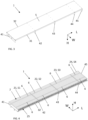
- FIG. 5 is an exemplary battery module 1 in a perspective view according to an example.
- the battery module 1 in FIG. 5 is based on the battery module shown in FIG. 4 . Similar to FIG. 4 , FIG. 5 also shows the battery module 1 in perspective view from above.
- the battery module 1 may comprise a top cover 7 configured to cover the plurality of battery cells 2 from above, as seen in the height direction H.
- the top cover 7 may be attached to the plurality of battery cells 2 and/or to the plurality of separate crossbeam members 41, 42, 43, 44, 45 by an adhesive, at least one fastener, and/or a weld.
- the top cover 7 may further be configured to provide structural rigidity to the battery module 1.
- the top cover 7 may be made of metal, such as aluminum, or by a polymer, such as a fiber reinforced polymer.
- the battery module 1 may have a first maximum height H1 and at least one of the first and second separate longitudinally extending beam members 31 may have a second maximum height H2, as measured in the height direction H, wherein the second maximum height H2 of the at least one of the first and second separate longitudinally extending beam members 31 is lower than the first maximum height H1 of the battery module 1.
- the side terminals 25 may be more easily accessible.
- At least two of the plurality of separate crossbeam members 41, 42, 43, 44, 45 may be identical. Additionally, or alternatively, the first and second separate longitudinally extending beam members 31, 32 may be identical.
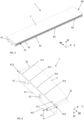
- FIG. 7 is an exemplary battery pack 100 in a side view according to an example.
- the battery pack 100 comprises one or more battery modules 1 as described herein.
- the battery pack 100 comprises two such battery modules 1, wherein the two battery modules 1 are arranged on top of each other, as seen in the height direction H.
- the battery pack 100 further comprises a housing 110 in which the at least two battery modules 1 are provided.
- Example 1 A battery module (1) for a battery pack (100), the battery module (1) having a longitudinal extension in a longitudinal direction (L), a width extension in a width direction (W) and a height extension in a height direction (H), the battery module (1) comprising:
- Example 2 The battery module (1) according to example 1, wherein the at least one group of stacked prismatic battery cells (21-24) is a group of stacked prismatic side terminal battery cells which are stacked next to each other in the longitudinal direction (L) with side terminals (25) thereof facing in a first direction corresponding to the width direction (W) and/or in a second direction which is opposite to the first direction.
- the at least one group of stacked prismatic battery cells (21-24) is a group of stacked prismatic side terminal battery cells which are stacked next to each other in the longitudinal direction (L) with side terminals (25) thereof facing in a first direction corresponding to the width direction (W) and/or in a second direction which is opposite to the first direction.
- Example 3 The battery module (1) according to any one of the preceding examples, wherein the battery cells of the at least one group of stacked prismatic battery cells (21-24) are fixed to each other by at least one strap (6) which is wrapped around the group of stacked prismatic battery cells (21-24).
- Example 4 The battery module (1) according to any one of the preceding examples, wherein the cooling plate bottom member (5) is mechanically connected to at least one crossbeam member within the plurality of separate crossbeam members (41-45) by one or more fasteners (411) and/or by one or more welds distributed along the width direction (W).
- Example 5 The battery module (1) according to any one of the preceding examples, wherein the battery module (1) has a first maximum height (H1) and wherein at least one of the first and second separate longitudinally extending beam members (31, 32) has a second maximum height (H2), as measured in the height direction (H), wherein the second maximum height (H2) of the at least one of the first and second separate longitudinally extending beam members (31, 32) is lower than the first maximum height (H1) of the battery module (1).
- Example 6 The battery module (1) according to example 5, wherein the at least one of the first and second separate longitudinally extending beam members (31, 32) is provided proximate, such as in abutment with, the cooling plate bottom member (5).
- Example 8 The battery module (1) according to any one of the preceding examples, comprising more than one group of the at least one group of stacked prismatic battery cells (21-24), wherein the first and second separate longitudinally extending beam members (31, 32), the plurality of separate crossbeam members (41-45) and the cooling plate bottom member (5) form a respective receiving space (S1-S4) for each group of stacked prismatic battery cells (21-24).
- Example 9 The battery module (1) according to any one of the preceding examples, wherein at least two of the plurality of separate crossbeam members (41-45) are identical.
- Example 10 The battery module (1) according to any one of the preceding examples, wherein the first and second separate longitudinally extending beam members (31, 32) are identical.
- Example 11 The battery module (1) according to any one of the preceding examples, wherein the cooling plate bottom member (5) comprises a coolant circuit configured to contain a coolant fluid.
- Example 13 The battery module (1) according to example 12, wherein the top cover (7) is attached to the plurality of battery cells (2) and/or to the plurality of separate crossbeam members (41-45) by an adhesive, at least one fastener, and/or a weld.
- Example 14 The battery module (1) according to any one of the preceding examples, further comprising a thermal interface material between the cooling plate bottom member (5) and the plurality of battery cells (2).
- Example 15 The battery module (1) according to example 3, wherein the at least one strap (6) is wrapped around an axis which corresponds to the width direction (W).
- Example 16 The battery module (1) according to example 11, wherein coolant circuit is fluidly connected to a fluid inlet (51) and a fluid outlet (52) for coolant fluid, wherein optionally the fluid inlet and/or outlet are located at an end portion of the battery module (1), as seen in the longitudinal direction (L).
- Example 17 The battery module (1) according to example 12 or 13, wherein the top cover (7) is configured to provide structural rigidity to the battery module (1).
- Example 18 A battery pack (100) comprising one or more battery modules (1) according to any one of the preceding examples.
Landscapes
- Chemical Kinetics & Catalysis (AREA)
- Electrochemistry (AREA)
- General Chemical & Material Sciences (AREA)
- Chemical & Material Sciences (AREA)
- Engineering & Computer Science (AREA)
- Manufacturing & Machinery (AREA)
- Aviation & Aerospace Engineering (AREA)
- Life Sciences & Earth Sciences (AREA)
- Sustainable Energy (AREA)
- Power Engineering (AREA)
- Transportation (AREA)
- Mechanical Engineering (AREA)
- Sustainable Development (AREA)
- Battery Mounting, Suspending (AREA)
- Secondary Cells (AREA)
Priority Applications (2)
| Application Number | Priority Date | Filing Date | Title |
|---|---|---|---|
| EP23218591.8A EP4576336A1 (fr) | 2023-12-20 | 2023-12-20 | Module de batterie, bloc-batterie et véhicule |
| US18/987,470 US20250210750A1 (en) | 2023-12-20 | 2024-12-19 | Battery module, a battery pack, and a vehicle |
Applications Claiming Priority (1)
| Application Number | Priority Date | Filing Date | Title |
|---|---|---|---|
| EP23218591.8A EP4576336A1 (fr) | 2023-12-20 | 2023-12-20 | Module de batterie, bloc-batterie et véhicule |
Publications (1)
| Publication Number | Publication Date |
|---|---|
| EP4576336A1 true EP4576336A1 (fr) | 2025-06-25 |
Family
ID=89385853
Family Applications (1)
| Application Number | Title | Priority Date | Filing Date |
|---|---|---|---|
| EP23218591.8A Pending EP4576336A1 (fr) | 2023-12-20 | 2023-12-20 | Module de batterie, bloc-batterie et véhicule |
Country Status (2)
| Country | Link |
|---|---|
| US (1) | US20250210750A1 (fr) |
| EP (1) | EP4576336A1 (fr) |
Citations (5)
| Publication number | Priority date | Publication date | Assignee | Title |
|---|---|---|---|---|
| DE102008059966A1 (de) * | 2008-12-02 | 2010-06-10 | Daimler Ag | Batterie mit mehreren in einem Zellenverbund angeordneten Batteriezellen |
| JP2012094456A (ja) * | 2010-10-28 | 2012-05-17 | Sanyo Electric Co Ltd | 電源装置 |
| WO2012133709A1 (fr) * | 2011-03-31 | 2012-10-04 | 三洋電機株式会社 | Dispositif de source d'alimentation, et véhicule comportant un dispositif de source d'alimentation |
| EP3926732A1 (fr) * | 2019-02-12 | 2021-12-22 | SANYO Electric Co., Ltd. | Module de batterie |
| US20220320653A1 (en) * | 2021-03-30 | 2022-10-06 | Aisin Corporation | Vehicular battery case and method for manufacturing vehicular battery case |
-
2023
- 2023-12-20 EP EP23218591.8A patent/EP4576336A1/fr active Pending
-
2024
- 2024-12-19 US US18/987,470 patent/US20250210750A1/en active Pending
Patent Citations (5)
| Publication number | Priority date | Publication date | Assignee | Title |
|---|---|---|---|---|
| DE102008059966A1 (de) * | 2008-12-02 | 2010-06-10 | Daimler Ag | Batterie mit mehreren in einem Zellenverbund angeordneten Batteriezellen |
| JP2012094456A (ja) * | 2010-10-28 | 2012-05-17 | Sanyo Electric Co Ltd | 電源装置 |
| WO2012133709A1 (fr) * | 2011-03-31 | 2012-10-04 | 三洋電機株式会社 | Dispositif de source d'alimentation, et véhicule comportant un dispositif de source d'alimentation |
| EP3926732A1 (fr) * | 2019-02-12 | 2021-12-22 | SANYO Electric Co., Ltd. | Module de batterie |
| US20220320653A1 (en) * | 2021-03-30 | 2022-10-06 | Aisin Corporation | Vehicular battery case and method for manufacturing vehicular battery case |
Also Published As
| Publication number | Publication date |
|---|---|
| US20250210750A1 (en) | 2025-06-26 |
Similar Documents
| Publication | Publication Date | Title |
|---|---|---|
| RU2684972C1 (ru) | Конструкция для установки аккумуляторной батареи | |
| US8968912B2 (en) | Method and apparatus for manufacturing a battery for a vehicle | |
| EP3981628B1 (fr) | Véhicule | |
| JP7136998B2 (ja) | カバー構造物を含むバッテリーパック及び電子デバイス並びに自動車 | |
| US20230123420A1 (en) | Battery frame, battery pack, electric vehicle, method of assembling a battery frame, and method of assembling a battery pack | |
| US20240363949A1 (en) | Stackable battery module mounting system | |
| US20250192309A1 (en) | Interlocking cell stack end plates for multi-tiered traction battery packs | |
| US20230411754A1 (en) | Variable array retention strategies | |
| EP4576336A1 (fr) | Module de batterie, bloc-batterie et véhicule | |
| EP4557455A1 (fr) | Agencement de module de batterie, bloc-batterie et véhicule | |
| EP4576327A1 (fr) | Module de batterie, bloc-batterie et véhicule | |
| EP4571938A1 (fr) | Module de batterie, bloc-batterie et véhicule | |
| EP4723328A1 (fr) | Ensemble module de batterie, bloc-batterie et véhicule | |
| EP4718596A1 (fr) | Bloc-batterie, véhicule et procédé d'assemblage d'un bloc-batterie | |
| EP4614636A1 (fr) | Bloc-batterie, véhicule et procédé de fabrication d'un bloc-batterie | |
| EP4738564A1 (fr) | Bloc-batterie et véhicule | |
| EP4738539A1 (fr) | Bloc-batterie et véhicule | |
| US20260128440A1 (en) | Battery pack and a vehicle | |
| EP4664603A1 (fr) | Ensemble empilement d'éléments de batterie, bloc-batterie, module de batterie, véhicule et procédé | |
| US20260128411A1 (en) | Battery pack and a vehicle | |
| EP4376168A1 (fr) | Empilement de batteries comprenant des modules de batterie et un système de refroidissement | |
| EP4645543A1 (fr) | Bloc-batterie, véhicule et procédé de fabrication d'un bloc-batterie | |
| EP4557475A1 (fr) | Paire de modules de batterie | |
| EP4653215A1 (fr) | Ensemble de montage de bloc-batterie, ensemble bloc-batterie, véhicule et procédé | |
| US20240014463A1 (en) | Battery stack comprising battery modules and a cooling plate |
Legal Events
| Date | Code | Title | Description |
|---|---|---|---|
| PUAI | Public reference made under article 153(3) epc to a published international application that has entered the european phase |
Free format text: ORIGINAL CODE: 0009012 |
|
| STAA | Information on the status of an ep patent application or granted ep patent |
Free format text: STATUS: THE APPLICATION HAS BEEN PUBLISHED |
|
| AK | Designated contracting states |
Kind code of ref document: A1 Designated state(s): AL AT BE BG CH CY CZ DE DK EE ES FI FR GB GR HR HU IE IS IT LI LT LU LV MC ME MK MT NL NO PL PT RO RS SE SI SK SM TR |
|
| STAA | Information on the status of an ep patent application or granted ep patent |
Free format text: STATUS: REQUEST FOR EXAMINATION WAS MADE |
|
| 17P | Request for examination filed |
Effective date: 20251205 |