EP4576345A1 - Sekundärbatterie - Google Patents
Sekundärbatterie Download PDFInfo
- Publication number
- EP4576345A1 EP4576345A1 EP24197457.5A EP24197457A EP4576345A1 EP 4576345 A1 EP4576345 A1 EP 4576345A1 EP 24197457 A EP24197457 A EP 24197457A EP 4576345 A1 EP4576345 A1 EP 4576345A1
- Authority
- EP
- European Patent Office
- Prior art keywords
- notch
- vent
- secondary battery
- region
- bending
- Prior art date
- Legal status (The legal status is an assumption and is not a legal conclusion. Google has not performed a legal analysis and makes no representation as to the accuracy of the status listed.)
- Pending
Links
Images


Classifications
-
- H—ELECTRICITY
- H01—ELECTRIC ELEMENTS
- H01M—PROCESSES OR MEANS, e.g. BATTERIES, FOR THE DIRECT CONVERSION OF CHEMICAL ENERGY INTO ELECTRICAL ENERGY
- H01M50/00—Constructional details or processes of manufacture of the non-active parts of electrochemical cells other than fuel cells, e.g. hybrid cells
- H01M50/30—Arrangements for facilitating escape of gases
- H01M50/342—Non-re-sealable arrangements
- H01M50/3425—Non-re-sealable arrangements in the form of rupturable membranes or weakened parts, e.g. pierced with the aid of a sharp member
-
- H—ELECTRICITY
- H01—ELECTRIC ELEMENTS
- H01M—PROCESSES OR MEANS, e.g. BATTERIES, FOR THE DIRECT CONVERSION OF CHEMICAL ENERGY INTO ELECTRICAL ENERGY
- H01M50/00—Constructional details or processes of manufacture of the non-active parts of electrochemical cells other than fuel cells, e.g. hybrid cells
- H01M50/10—Primary casings; Jackets or wrappings
- H01M50/102—Primary casings; Jackets or wrappings characterised by their shape or physical structure
- H01M50/103—Primary casings; Jackets or wrappings characterised by their shape or physical structure prismatic or rectangular
-
- H—ELECTRICITY
- H01—ELECTRIC ELEMENTS
- H01M—PROCESSES OR MEANS, e.g. BATTERIES, FOR THE DIRECT CONVERSION OF CHEMICAL ENERGY INTO ELECTRICAL ENERGY
- H01M50/00—Constructional details or processes of manufacture of the non-active parts of electrochemical cells other than fuel cells, e.g. hybrid cells
- H01M50/10—Primary casings; Jackets or wrappings
- H01M50/147—Lids or covers
- H01M50/148—Lids or covers characterised by their shape
- H01M50/15—Lids or covers characterised by their shape for prismatic or rectangular cells
-
- H—ELECTRICITY
- H01—ELECTRIC ELEMENTS
- H01M—PROCESSES OR MEANS, e.g. BATTERIES, FOR THE DIRECT CONVERSION OF CHEMICAL ENERGY INTO ELECTRICAL ENERGY
- H01M50/00—Constructional details or processes of manufacture of the non-active parts of electrochemical cells other than fuel cells, e.g. hybrid cells
- H01M50/30—Arrangements for facilitating escape of gases
-
- Y—GENERAL TAGGING OF NEW TECHNOLOGICAL DEVELOPMENTS; GENERAL TAGGING OF CROSS-SECTIONAL TECHNOLOGIES SPANNING OVER SEVERAL SECTIONS OF THE IPC; TECHNICAL SUBJECTS COVERED BY FORMER USPC CROSS-REFERENCE ART COLLECTIONS [XRACs] AND DIGESTS
- Y02—TECHNOLOGIES OR APPLICATIONS FOR MITIGATION OR ADAPTATION AGAINST CLIMATE CHANGE
- Y02E—REDUCTION OF GREENHOUSE GAS [GHG] EMISSIONS, RELATED TO ENERGY GENERATION, TRANSMISSION OR DISTRIBUTION
- Y02E60/00—Enabling technologies; Technologies with a potential or indirect contribution to GHG emissions mitigation
- Y02E60/10—Energy storage using batteries
Definitions
- the present disclosure relates to a secondary battery capable of being charged with and discharging electricity.
- Secondary batteries are energy storage units that may be charged with and discharged of electricity. Secondary batteries have been widely used in various units that use electricity as a power source. For example, secondary batteries have been used as energy storage units in a variety of devices ranging from small devices, such as mobile phones, laptops, and tablets to large devices, such as vehicles and aircraft. In particular, in recent years, the use of secondary batteries as a vehicle power source has been actively sought.
- Secondary batteries may be classified into lead-acid batteries, nickel cadmium batteries, nickel hydrogen batteries, lithium ion batteries, etc., depending on materials of the electrodes. Secondary batteries for each type may be appropriately selected depending on design capacity, usage environment, etc. Lithium-ion batteries may be implemented with relatively high voltage and capacity as compared to other types of secondary batteries. Accordingly, lithium-ion batteries have been widely used in fields that require high-density energy storage, such as vehicle battery packs, etc.
- Secondary batteries such as lithium-ion batteries, include a cathode material, an anode material, a separator, and an electrolytic solution, as main components.
- the cathode material and anode material are arranged with a separator formed of an insulating material therebetween, and charging or discharging may be achieved by the movement of ions through the electrolytic solution.
- Korean Application Publication No. 10-2023-0048765 discloses a secondary battery including such a vent (safety vent).
- An aspect of the present disclosure may provide a secondary battery capable of improving a discharge function of internal pressure through a vent, etc.
- the secondary battery of the present disclosure may be widely applied in green technology fields, such as electric vehicles, battery charging stations, and solar power generation and wind power generation using batteries.
- the secondary battery of the present disclosure may be used in eco-friendly electric vehicles, hybrid vehicles, etc. to ameliorate climate change by suppressing air pollution and greenhouse gas emissions.
- a secondary battery includes: a case accommodating an electrode assembly therein; a cap plate sealing an opening of the case; and a vent provided in one or more of the case and the cap plate, wherein the vent includes: a notch induced to rupture according to internal pressure of the case; and one or more bending guides inducing roll up deformation of each ruptured region.
- the notch may include: a pair of first notches extending in a first direction on an outer surface of the vent and spaced apart from each other in a second direction; and a second notch extending between the pair of first notches.
- the second notch may be disposed to equally divide the first notch into left and right portions in the first direction and extend in the second direction perpendicular to the first direction.
- the second notch may be formed between the pair of first notches and extend obliquely at a predetermined angle with respect to the first notch.
- the first notch may have a first depth from the outer surface
- the second notch may have a second depth from the outer surface, and the second depth may be formed to be deeper than the first depth by a predetermined amount.
- the notch may form an "H" shape in plan view.
- the bending guide may induce each region to be rolled up toward the outer surface of the vent to be deformed.
- the bending guide may be concavely bent toward the inside of the case, extend in a second direction, and a plurality of bending guides may be arranged to be spaced apart from each other at predetermined intervals in a first direction, perpendicular to the second direction.
- the bending guide may be formed such that one end in the second direction is spaced apart from the notch by a predetermined distance, and an opposite end corresponding to the one end is spaced apart from the notch by a predetermined distance.
- the bending guide may include a first bending guide portion disposed in a first region divided by the second notch, extending in a second direction, provided in plural to be spaced apart from each other by a predetermined interval in the first direction, and inducing the first region to be rolled up and deformed to one side.
- a gap between a pair of first bending guide portions that are relatively adjacent to the second notch may be formed to be greater, by a predetermined amount, than a gap between another pair of first bending guide portions that are relatively spaced apart from the second notch.
- the bending guide may include a second bending guide disposed in a second region corresponding to the first region, extending in the second direction, provided in a plural to be spaced apart from each other by a predetermined interval in the first direction, and inducing the second region to be rolled up and deformed to the opposite side corresponding to the one side.
- a secondary battery described in this specification may include a battery that may be charged and discharged.
- the secondary battery may include a lead-acid battery, a nickel cadmium battery, a nickel hydride battery, a lithium ion battery, etc.
- the secondary battery is a lithium ion battery.
- lithium-ion batteries may have advantages, such as lightweightedness, high energy density, and low self-discharge rate.
- the technical concepts described in this specification are applicable to suitable types of batteries other than lithium ion batteries.
- the secondary battery described in this specification may include a single physical unit or a group unit in which a plurality of the above units are combined.
- secondary batteries may include battery cells, battery modules, battery packs, etc., according to classification criteria commonly used in the vehicle field.
- the secondary battery is a battery cell as a single unit.
- a battery cell is a basic unit of a battery pack including a cathode material, an anode material, a separator, and an electrolytic solution.
- the technical concept described in this specification may be applied to other suitable types of group units, such as battery modules and battery packs, as necessary.
- the secondary battery described herein may encompass various packaging types.
- secondary batteries may be packaged as cylindrical batteries, prismatic batteries, pouch-type batteries, coin-type batteries, etc. according to the classification criteria commonly used in the related field.
- the secondary battery is packaged as a prismatic type batteries.
- Prismatic packaging also referred to as prismatic batteries, may generally have advantages in terms of durability, safety, and convenience of mounting.
- the technical concept described in this specification may also be applied to other suitable packaging types, such as cylindrical, pouch-type, and coin-type, if necessary.
- the secondary battery described herein may be used in various units that require electrical energy.
- secondary batteries may be suitably used in vehicle fields in which electrical energy is used as a main or auxiliary power source.
- secondary batteries may be suitably used in the field of aircraft, such as personal aircraft, unmanned aerial vehicles, and drones, in the field of electronic devices, such as mobile phones, laptops, and tablets, and in the field of electric tools, such as electric drills, electric grinders, and electric hammers.
- the secondary battery described in this specification may be widely utilized in various units operated based on electrical energy in addition to the above.
- FIG. 1A is a schematic perspective view of a secondary battery according to an exemplary embodiment.
- FIG. 1B is a schematic exploded perspective view of the secondary battery illustrated in FIG. 1A .
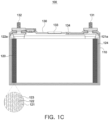
- FIG. 1C is a schematic internal cross-sectional view of the secondary battery illustrated in FIG. 1A .
- the present exemplary embodiment illustrates one battery cell packaged in a prismatic shape.
- the case 110 may provide an internal space in which an electrode assembly 120 or the like may be accommodated.
- the case 110 is illustrated to have a substantially rectangular parallelepiped shape.
- the case 110 may include an opening 111 connected to the internal space.
- the opening 111 is illustrated as being provided at the top of the case 110. However, the position of the opening 111 may be changed as needed and is not limited to the example.
- the opening 111 may function as a passage for insertion of the electrode assembly 120 or the like.
- the opening 111 may function as a connection space for electrical connection between the electrode assembly 120 and an electrode terminal.
- the opening 111 may be closed by a cap plate 130.
- a material of the case 110 may be appropriately selected in consideration of thermal and electrical conductivity, rigidity corresponding to swelling of the electrode assembly 120, processability, manufacturing costs, etc.
- the case 110 may be formed of a metal material including aluminum or aluminum alloy.
- the secondary battery 100 may include the electrode assembly 120.
- the electrode assembly 120 may be disposed in the internal space of the case 110. If necessary, the electrode assembly 120 may be accommodated in an insulating bag 124 and disposed inside the case 110.
- the electrode assembly 120 may include a cathode material 121.
- the cathode material 121 may include a cathode current collector and a cathode active material.
- the cathode current collector may include aluminum, aluminum alloy, etc.
- the cathode active material may include lithium cobalt oxide, lithium manganate, lithium nickelate, and lithium iron phosphate.
- the cathode active material may be coated on a surface of the cathode current collector.
- a partial region of the cathode current collector not coated with the cathode active material may function as a cathode tab 121a.
- a plurality of cathode tabs 121a may be provided, and some or all of the plurality of cathode tabs 121a may be bonded to each other.
- the electrode assembly 120 may include an anode material 122.
- the anode material 122 may include an anode current collector and an anode active material.
- the anode current collector may include copper, copper alloy, nickel, nickel alloy, etc.
- the anode active material may include carbon, silicon, etc.
- the anode active material may be coated on a surface of the anode current collector. A partial region of the anode current collector not coated with the anode active material may function as the anode tab 122a.
- a plurality of anode tabs 122a may be provided, and some or all of the plurality of anode tabs 122a may be bonded to each other.
- the electrode assembly 120 may include the separator 123.
- the separator 123 may be disposed between the cathode material 121 and the anode material 122.
- the separator 123 may function to limit physical contact between the cathode material 121 and the anode material 122 and provide a passage for the movement of ions.
- the separator 123 may be formed of a polymer material including polyethylene, polypropylene, etc.
- the separator 123 may include dry and wet separators.
- the separator 123 may include a coating layer including a ceramic coating layer.
- the electrode assembly 120 may be formed by arranging the above components by winding, stacking, etc.
- the electrode assembly 120 may be formed in a structure in which the cathode material 121, the anode material 122, and the separator 123 are wound around a longitudinal or transverse axis.
- the electrode assembly 120 may be formed in a structure in which the above winding structure is compressed in a direction approximately perpendicular to a winding axis.
- the winding structure may be referred to as a 'jelly roll' or the like in the art.
- the electrode assembly 120 may be formed in a structure in which the cathode material 121, the anode material 122, and the separator 123 are stacked.
- a plurality of unit separators 123 continuous in the longitudinal direction are sequentially folded and stacked according to the stacking of the cathode material 121 and the anode material 122.
- the stack structure may be referred to as 'stack and folding,' ⁇ z-folding,' etc. in the art.
- the arrangement of each component of the electrode assembly 120 is not particularly limited.
- the electrode assembly 120 may have various arrangements other than those illustrated above.
- the electrode assembly 120 may be a combination of multiple units.
- the electrode assembly 120 may include units wound in a jelly roll manner, and two or more of the units may be combined to form the electrode assembly 120.
- the electrode assembly 120 is a combination of two jelly roll units.
- the electrode assembly 120 may include units wound in a stack-and-folding manner, and two or more of the units may be combined to form the electrode assembly 120.
- the electrode assembly 120 may be accommodated in the internal space of the case 110 together with an electrolytic solution.
- the electrolytic solution may be formed of an organic solvent including a lithium salt.
- the lithium salt may include liquid or gel lithium hexafluorophosphate (LiPF 6 ) and lithium tetrafluoroborate (LiBF 4 ), etc
- the organic solvent may include cyclic carbonates, such as ethylene carbonate (EC), propylene carbonate (PC), etc. and linear carbonates, such as diethyl carbonate (DEC), dimethyl carbonate (DMC), and such as ethyl methyl carbonate (EMC).
- the electrolytic solution may be omitted or replaced.
- the liquid or gel electrolytic solution may be omitted.
- the secondary battery 100 may include the cap plate 130.
- the cap plate 130 may be formed to close the opening 111.
- the cap plate 130 is illustrated as having a square plate shape corresponding to the opening 111.
- the cap plate 130 may be coupled to the case 110 to seal the internal space of the case 110 in which the electrode assembly 120 is disposed.
- the cap plate 130 may be welded and bonded to the case 110 using ultrasonic welding, laser welding, or the like.
- a cathode terminal 131 and an anode terminal 132 may be disposed on the cap plate 130.
- the cathode terminal 131 may be electrically connected to a cathode tab 121a of the electrode assembly 120
- the anode terminal 132 may be electrically connected to an anode tab 122a of the electrode assembly 120.
- the cap plate 130 may include an electrolytic solution injection port 134.
- the electrolytic solution injection port 134 may be used to inject electrolytic solution into the internal space of the case 110.
- the electrolytic solution injection port 134 is disposed adjacent to a vent 133 in a central region of the cap plate 130.
- the position of the electrolytic solution injection port 134 may be changed variously and is not limited to the example.
- the electrolytic solution injection port 134 may be appropriately sealed after injection of the electrolytic solution, a formation process, etc.
- the electrolytic solution injection port 134 may be sealed by press-fitting a ball-shaped sealing member formed of polymer resin.
- the cap plate 130 may include the vent 133.
- the vent 133 is disposed between the cathode terminal 131 and the anode terminal 132.
- the position of the vent 133 may be changed variously as needed, and is not limited to the example.
- the vent 133 may be disposed in or added to the case 110.
- the vent 133 may be formed to be open in response to internal pressure of the case 110.
- the vent 133 may function to discharge the internal pressure to the outside of the case 110 to contribute to the stabilization of the internal elements of the case 110.
- the vent 133 may more appropriately respond to or discharge internal pressure through components that will be described later.
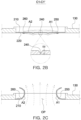
- FIG. 2A is a schematic perspective view of a vent according to an exemplary embodiment.
- FIG. 2B is a schematic cross-sectional view of the vent illustrated in FIG. 2A .
- vents according to each exemplary embodiment will be given new reference numerals and described below.
- a vent 200 according to the present exemplary embodiment may be disposed in one or more of the cap plate 130 and the case 110.
- a case in which the vent 200 is disposed in the cap plate 130 is illustrated, and the following description will focus thereon.
- FIG. 5 which will be described later, illustrates a case in which the vent 200 is disposed in the case 110.
- the vent 200 may include an outer surface 210 and an inner surface 220.
- the outer surface 210 refers to a surface disposed toward the outside of the case 110
- the inner surface 220 refers to a surface disposed toward the inside of the case 110.
- the vent 200 may be formed to extend in a first direction E1 and a second direction E2.
- the first direction E1 is illustrated as a direction corresponding to a longitudinal direction E1 of the cap plate 130
- the second direction E2 is illustrated as a direction corresponding to a width direction E2 of the cap plate 130.
- the illustrated cap plate 130 has a length in the longitudinal direction E1 larger than a length in the width direction E2.
- the first direction E1 is the longitudinal direction E1 and the second direction E2 is the width direction E2.
- vent 200 may include notches 230 and 240.
- the notches 230 and 240 may be formed to induce rupture of the vent 200 in response to the internal pressure of the case 110. That is, the notches 230 and 240 may define a rupture position of the vent 200.
- the vent 200 may be designed to rupture in a position corresponding to the notches 230 and 240 to discharge internal pressure.
- the notches 230 and 240 may be formed to be recessed to a predetermined degree in the thickness direction from the outer surface 210 of the vent 200 toward the inner surface 220.
- the notches 230 and 240 may generally have the shape of recess formed on the outer surface 210 of the vent 200.
- the notches 230 and 240 may have a predetermined cross-sectional shape and extend in the longitudinal direction.
- the notches 230 and 240 are illustrated as having an approximately "V" shaped cross-section.
- the portion in which the notches 230 and 240 are formed may have a thickness smaller than a portion in which the notches 230 and 240 are not formed.
- the notches 230 and 240 may extend from the outer surface 210 of the vent 200, while forming a predetermined line or pattern. In some exemplary embodiments, the notches 230 and 240 may extend in the longitudinal direction E1 or the width direction E2 of the vent 200. Alternatively, in some other exemplary embodiments, the notches 230 and 240 may extend obliquely at a predetermined angle with the longitudinal direction E1 or the width direction E2 of the vent 200.
- the notches 230 and 240 may be formed to extend with a predetermined length in the longitudinal direction E1 and the width direction E2 of the vent 200, respectively.
- the notches 230 and 240 may include a first notch 230 extending in the longitudinal direction E1.
- a pair of first notches 230 may be provided, and the pair of first notches 230 may be arranged to be spaced apart from each other at a predetermined interval in the width direction E2.
- the pair of first notches 230 may be sufficiently spaced apart from each other in the width direction E2.
- each first notch 230 is disposed adjacent to an outer boundary line (edge) of the vent 200 to ensure a gap in the width direction E2.
- the notches 230 and 240 may include a second notch 240 extending in the width direction E2.
- the second notch 240 may be formed to extend in the width direction E2 between the pair of first notches 230.
- One end of the second notch 240 may form a contact point with the first notch 230 on one side, and the opposite end may form a contact point with the first notch 230 on the opposite side.
- the second notch 240 is disposed to be substantially perpendicular to the first notch 230 to form a contact point.
- a length of the second notch 240 may be different from a length of the first notch 230.
- the length of the second notch 240 is shorter than the length of the first notch 230 by a predetermined amount.
- the second notch 240 may be disposed in the center of the first notch 230 in the longitudinal direction. That is, the second notch 240 may be disposed to equally divide the first notch 230 extending in the longitudinal direction E1 to left and right sides.
- the first and second notches 230 and 240 as described above form an approximately ⁇ H' shape in plan view.
- the second notch 240 may divide a first region A1 and a second region A2.
- the first region A1 refers to one side region in the longitudinal direction E1 of the vent 200 from the second notch 240
- the second region A2 refers to a region on the opposite side of the one side region. Based on the drawing, the vent 200 may be divided into the first region A1, which is the right region of the second notch 240, and the second region A2, which is the corresponding left region.
- the first and second notches 230 and 240 may have different depths.
- the first notch 230 may be formed to have a first depth D1 from the outer surface 210, and the second notch 240 may have a second depth D2 greater than the first depth D1 by a predetermined amount.
- a depth difference between the first and second notches 230 and 240 as described above may be implemented through pressing force of a press applied when forming the first and second notches 230 and 240.
- the second notch 240 may be intended to rupture before the first notch 230. That is, according to some operating examples, as the internal pressure of the case 110 increases, the second notch 240 may be preferentially induced to rupture, and then the first notch 230 may be induced to rupture.
- the vent 200 may include bending guides 250 and 260.
- the bending guides 250 and 260 may function to induce appropriate deformation of each of the regions A1 and A2 when the notches 230 and 240 rupture.
- the bending guides 250 and 260 may function to reduce unnecessary stress applied to the notches 230 and 240 by accommodating a temporary change in the internal pressure of the case 110 before the rupture of the notches 230 and 240.
- the bending guides 250 and 260 may be formed to be concavely bent toward the inside of the case 110. That is, the bending guides 250 and 260 may be formed by bending the outer surface 210 of the vent 200 concavely toward the inside of the case 110. According to the curvature of the outer surface 210, the corresponding inner surface 220 may protrude convexly toward the inside of the case 110.
- the bending guides 250 and 260 may have a predetermined cross-sectional shape and extend in the width direction E2 of the vent 200.
- the bending guides 250 and 260 are illustrated as having a partially arc-shaped cross-sectional shape.
- the cross-sectional shape of the bending guides 250 and 260 may be modified variously as needed as long as it satisfies functional elements of the bending guides 250 and 260, which will be described later, and is not limited to the example.
- the bending guides 250 and 260 may be implemented through a material, thickness, etc. rather than a structure, a shape, etc.
- the bending guides 250 and 260 may extend in the width direction E2 between the pair of first notches 230.
- the bending guides 250 and 260 may extend in the width direction E2 to occupy most of a gap G1 between the pair of first notches 230.
- the bending guides 250 and 260 may be formed to extend in the width direction E2 so as to occupy at least 80% of the gap G1 between the pair of first notches 230.
- the bending guides 250 and 260 extend to intersect the pair of first notches 230 in the width direction E2 and completely occupy the gap G1 between the pair of first notches 230.
- a plurality of bending guides 250 and 260 may be provided, and the plurality of bending guides 250 and 260 may be arranged at predetermined intervals in a direction in which the first notch 230 extends. That is, the plurality of bending guides 250 and 260 may be arranged to be spaced apart from each other in the longitudinal direction E1. However, the plurality of bending guides 250 and 260 may be appropriately omitted in the region in which the second notch 240 is formed. That is, the plurality of bending guides 250 and 260 may be arranged at a predetermined interval from the second notch 240 and disposed in the remaining region of the vent 200 in which the second notch 240 is not formed.
- the bending guides 250 and 260 may include a first bending guide portion 250 and a second bending guide 260.
- the first bending guide portion 250 may be disposed in the first region A1, and the second bending guide 260 may be disposed in the second region A2.
- the first and second bending guides 250 and 260 may be formed identically or similarly to each other except that their arrangement positions are different.
- a plurality of first bending guide portions 250 may be provided in the first region A1.
- the plurality of first bending guide portions 250 may be spaced apart from each other in the longitudinal direction E1 of the vent 200 within the first region A1.
- two first bending guide portions 250 are illustrated.
- a plurality of second bending guides 260 may be provided in the second region A2.
- the plurality of second bending guides 260 may be spaced apart from each other in the longitudinal direction E1 of the vent 200 within the second region A2.
- two second bending guides 260 are illustrated.
- the numbers of the first and second bending guides 250 and 260 may not necessarily be equal to each other, and the numbers of the first and second bending guides 250 and 260 may be different as needed.
- the first bending guide portion 250 may be disposed at a predetermined gap G2 from the second notch 240 or another adjacent first bending guide portion 250.
- each gap G2 of the first bending guide portion 250 is illustrated as being the same.
- the second bending guide 260 may be disposed at a predetermined distance G3 from the second notch 240 or another adjacent second bending guide 260.
- each gap G3 of the second bending guide 260 is illustrated as being the same.
- each gap G2 of the first bending guide portion 250 or each gap G3 of the second bending guide 260 may be formed to be different partially. This is illustrated in FIG. 4A , which will be described later.
- the bending guides 250 and 260 as described above may function to correspond to a temporary change in the internal pressure of the case 110.
- the vent 200 including a plurality of bending guides 250 and 260 may be induced to be elastically deformed to a certain degree based on the width direction E2 as axis in response to a temporary change in internal pressure of the case 110.
- the above elastic deformation is somewhat exaggerated for ease of understanding.
- the plurality of bending guides 250 and 260 extending in the width direction E2 may appropriately assist elastic deformation in the width direction E2 as an axis as described above. This prevents unnecessary fatigue load from accumulating in the notches 230 and 240.
- the plurality of bending guides 250 and 260 extending in the width direction E2 may function to appropriately limit deformation of the vent 200 in the longitudinal direction E1 as an axis. This simplifies factors, such as external force, deformation, etc. to be considered in the design of the vent 200, thereby facilitating optimization of design for materials, specifications, etc.
- FIG. 2C is a schematic operating diagram of the vent illustrated in FIG. 2A .
- the vent 200 may be opened appropriately depending on the internal pressure of the case 110. That is, in the vent 200, the notches 230 and 240 may rupture depending on the internal pressure of the case 110 to form a type of outlet OP, and the internal pressure may be discharged through the outlet OP.
- the vent 200 may be opened as the second notch 240 ruptures due to the internal pressure of the case 110 and then the first notch 230 ruptures.
- the rupture order of the first and second notches 230 and 240 is not limited thereto.
- the vent 200 in which the first and second notches 230 and 240 rupture may secure the outlet OP as the first and second regions A1 and A2 are rolled up to side ends in the longitudinal direction E1, respectively. That is, the first region A1 may be induced to be deformed in a roll shape by the plurality of first bending guide portions 250 and rolled up to one side (right side). In addition, the second region A2 may be induced to be deformed in a roll shape by the plurality of second bending guides 260 and rolled up to the opposite side (left side).
- the first and second regions A1 and A2 may be induced to be deformed to be rolled up toward the outer surface 210 of the vent 200 according to the direction of the first and second bending guides 250 and 260.
- ⁇ roll up' the shape in which each region A1 and A2 is rolled up toward the outer surface 210 to be deformed as described above.
- the first and second regions A1 and A2 are rolled up as described above, so that a sufficient outlet OP may be secured after the rupture of the first and second notches 230 and 240. That is, the first region A1 is rolled up to the right in the drawing, and the second region A2 is rolled up to the left in the drawing, so that the sufficient outlet OP region may be secured between the first and second regions A1 and A2. Accordingly, more smooth discharge of the internal pressure of the case 110 may be induced.
- first and second regions A1 and A2 rolled up as described above may reduce the occurrence of sharp edges after rupture. In the case of a general vent structure, sharp edges, etc. are exposed as it is after rupture, which may cause secondary damage to adjacent components.
- first and second regions A1 and A2 rolled up as described above may reduce problems, such as interfering with the discharge of internal pressure due to re-deformation of each of the regions A1 and A2 after rupture.
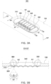
- FIG. 3A is a schematic perspective view of a vent according to another exemplary embodiment.
- FIG. 3B is a schematic cross-sectional view of the vent illustrated in FIG. 3A .
- the bending guides 350 and 360 may include a first bending guide portion 350 disposed in the first region A1 and a second bending guide 360 disposed in the second region A2.
- a plurality of first bending guide portions 350 may be provided, and in the present exemplary embodiment, three first bending guide portions 350 are illustrated.
- a plurality of second bending guides 360 may be provided, and in the present exemplary embodiment, three second bending guides 360 are illustrated.
- the gaps G2 and G3 between the first and second bending guides 350 and 360 may be formed to be equal. This is generally similar to the exemplary embodiment described above.
- FIG. 4A is a schematic perspective view of a vent according to another exemplary embodiment in the present disclosure.
- FIG. 4B is a schematic cross-sectional view of the vent illustrated in FIG. 4A .
- a vent 400 may include notches 430 and 440.
- the bending guides 450 and 460 may be formed by bending an outer surface 410 of the vent 400 concavely toward the inside of the case 110.
- the bending guides 450 and 460 may extend in the width direction E2 between the pair of first notches 430.
- both ends of the bending guides 450 and 460 may be spaced apart from the first notch 430 by predetermined gaps G4 and G5. This is generally similar to the exemplary embodiment described above.
- the bending guides 450 and 460 may include a plurality of first bending guide portions 450 arranged in the first region A1 and a plurality of second bending guides 460 arranged in the second region A2. In the present exemplary embodiment, four first and second bending guides 450 and 460 are illustrated.
- the vent 500 is disposed adjacent to one corner at a lower end of a front surface of the case 110.
- the position of the vent 500 in the case 110 may be changed variously as needed, and is not limited to the example.
- the vent 500 may be formed substantially similar to the exemplary embodiments described above, except for the arrangement position.
- the vent 500 may include notches 530 and 540, and the notches 530 and 540 may include a pair of first notches 530 and a second notch 540 extending between the pair of first notches 530.
- the vent 500 may include bending guides 550 and 560, and the bending guides 550 and 560 may include a plurality of first bending guide portions 550 disposed in the first region A1 and a plurality of second bending guides 560 disposed in the second region A2. In the present exemplary embodiment, three first and second bending guides 550 and 560 are illustrated.
- the vent 500 of the present exemplary embodiment is partially different from the exemplary embodiments described above in the configuration of the second notch 540. That is, the second notch 540 of the present exemplary embodiment may be formed to extend obliquely between the pair of first notches 530. This is in contrast to the exemplary embodiments described above in which the second notches 240, 340, and 440 are formed to extend substantially perpendicular to the first notches 230, 330, and 430.
- the second notch 540 may extend to form a predetermined angle S1 with the pair of first notches 530, and the angle S1 may be set to a predetermined acute angle.
- the second notch 540 may be disposed to form the angle S1 of 30 to 60 degrees with the pair of first notches 530.
- the second notch 540 as described above may induce more smooth rupture at a contact point portion with the first notch 530. That is, since the second notch 540 is in contact with the first notch 530 at a predetermined acute angle, appropriate rupture at the acute angle portion may be induced in response to the internal pressure of the case 110. Meanwhile, after the rupture, the vent 500 may be opened as the rupture is induced along each of the first notch 530 and the second notch 540 based on the contact point. Thereafter, the first and second regions A1 and A2 of the vent 500 are rolled up by the first and second bending guides 550 and 560, respectively, thereby achieving the operations and effects similar to the exemplary embodiments described above.
- the secondary battery according to exemplary embodiments of the present disclosure may include the vent opened in response to the internal pressure of the case.
- each region based on the notch may be induced to be rolled up and deformed after rupture. That is, based on the second notch, roll-up deformation to one side may be induced in the first region, and roll-up deformation to the opposite side may be induced in the second region on the opposite side.
- the structure and shape of the notch, the bending guide disposed in each region, etc. proposed in the exemplary embodiments of the present disclosure may appropriately induce the roll-up deformation described above.
- the secondary battery according to the exemplary embodiments of the present disclosure may appropriately secure and maintain the area of the outlet after the vent ruptures through the roll-up of the vent as described above. In some situations, this may contribute to rapidly stabilizing heat, pressure, and by-products inside the secondary battery.
- the secondary battery according to exemplary embodiments of the present disclosure may appropriately respond to a change in the internal pressure of the case through the bending guide. That is, in the exemplary embodiments of the present disclosure, the bending guide may accommodate the internal pressure within an allowable value before rupture of the vent and induce appropriate elastic deformation. The bending guide may function to prevent unnecessary fatigue load from accumulating in the notch and limit the direction of elastic deformation of the vent to a certain direction.
Landscapes
- Chemical & Material Sciences (AREA)
- Chemical Kinetics & Catalysis (AREA)
- Electrochemistry (AREA)
- General Chemical & Material Sciences (AREA)
- Gas Exhaust Devices For Batteries (AREA)
- Sealing Battery Cases Or Jackets (AREA)
Applications Claiming Priority (1)
| Application Number | Priority Date | Filing Date | Title |
|---|---|---|---|
| KR1020230185129A KR20250094388A (ko) | 2023-12-18 | 2023-12-18 | 이차전지 |
Publications (1)
| Publication Number | Publication Date |
|---|---|
| EP4576345A1 true EP4576345A1 (de) | 2025-06-25 |
Family
ID=92633215
Family Applications (1)
| Application Number | Title | Priority Date | Filing Date |
|---|---|---|---|
| EP24197457.5A Pending EP4576345A1 (de) | 2023-12-18 | 2024-08-30 | Sekundärbatterie |
Country Status (4)
| Country | Link |
|---|---|
| US (1) | US20250202029A1 (de) |
| EP (1) | EP4576345A1 (de) |
| KR (1) | KR20250094388A (de) |
| CN (1) | CN120184499A (de) |
Cited By (2)
| Publication number | Priority date | Publication date | Assignee | Title |
|---|---|---|---|---|
| EP4657638A1 (de) * | 2024-05-27 | 2025-12-03 | Samsung Sdi Co., Ltd. | Sekundärbatterie mit entgasungsvorrichtung und verfahren zur herstellung davon |
| EP4657639A1 (de) * | 2024-05-27 | 2025-12-03 | Samsung Sdi Co., Ltd. | Sekundärbatterie mit entgasungsvorrichtung und verfahren zur herstellung davon |
Citations (7)
| Publication number | Priority date | Publication date | Assignee | Title |
|---|---|---|---|---|
| US9118061B2 (en) * | 2010-08-13 | 2015-08-25 | Samsung Sdi Co., Ltd. | Secondary battery |
| US20170279098A1 (en) * | 2016-03-22 | 2017-09-28 | Samsung Sdi Co., Ltd. | Rechargeable battery |
| US20190237729A1 (en) * | 2016-09-20 | 2019-08-01 | Samsung Sdi Co., Ltd. | Secondary battery with embossed safety vent |
| US20210359373A1 (en) * | 2017-01-27 | 2021-11-18 | Robert Bosch Gmbh | Rupture valve and energy storage device |
| EP4120458A1 (de) * | 2020-03-09 | 2023-01-18 | SANYO Electric Co., Ltd. | Gasentladungsventil für batterie und batterie |
| KR20230048765A (ko) | 2021-10-05 | 2023-04-12 | 삼성에스디아이 주식회사 | 이차 전지 및 이를 포함하는 전지 모듈 |
| US20230223644A1 (en) * | 2021-08-31 | 2023-07-13 | Contemporary Amperex Technology Co., Limited | Pressure relief apparatus, battery cell, battery, and electrical device |
-
2023
- 2023-12-18 KR KR1020230185129A patent/KR20250094388A/ko active Pending
-
2024
- 2024-08-28 US US18/817,225 patent/US20250202029A1/en active Pending
- 2024-08-29 CN CN202411195258.1A patent/CN120184499A/zh active Pending
- 2024-08-30 EP EP24197457.5A patent/EP4576345A1/de active Pending
Patent Citations (7)
| Publication number | Priority date | Publication date | Assignee | Title |
|---|---|---|---|---|
| US9118061B2 (en) * | 2010-08-13 | 2015-08-25 | Samsung Sdi Co., Ltd. | Secondary battery |
| US20170279098A1 (en) * | 2016-03-22 | 2017-09-28 | Samsung Sdi Co., Ltd. | Rechargeable battery |
| US20190237729A1 (en) * | 2016-09-20 | 2019-08-01 | Samsung Sdi Co., Ltd. | Secondary battery with embossed safety vent |
| US20210359373A1 (en) * | 2017-01-27 | 2021-11-18 | Robert Bosch Gmbh | Rupture valve and energy storage device |
| EP4120458A1 (de) * | 2020-03-09 | 2023-01-18 | SANYO Electric Co., Ltd. | Gasentladungsventil für batterie und batterie |
| US20230223644A1 (en) * | 2021-08-31 | 2023-07-13 | Contemporary Amperex Technology Co., Limited | Pressure relief apparatus, battery cell, battery, and electrical device |
| KR20230048765A (ko) | 2021-10-05 | 2023-04-12 | 삼성에스디아이 주식회사 | 이차 전지 및 이를 포함하는 전지 모듈 |
Cited By (2)
| Publication number | Priority date | Publication date | Assignee | Title |
|---|---|---|---|---|
| EP4657638A1 (de) * | 2024-05-27 | 2025-12-03 | Samsung Sdi Co., Ltd. | Sekundärbatterie mit entgasungsvorrichtung und verfahren zur herstellung davon |
| EP4657639A1 (de) * | 2024-05-27 | 2025-12-03 | Samsung Sdi Co., Ltd. | Sekundärbatterie mit entgasungsvorrichtung und verfahren zur herstellung davon |
Also Published As
| Publication number | Publication date |
|---|---|
| US20250202029A1 (en) | 2025-06-19 |
| CN120184499A (zh) | 2025-06-20 |
| KR20250094388A (ko) | 2025-06-25 |
Similar Documents
| Publication | Publication Date | Title |
|---|---|---|
| EP1901365B1 (de) | Batteriezelle mit schmaler Nut auf der Oberfläche und Batteriesatz damit | |
| EP4576345A1 (de) | Sekundärbatterie | |
| WO2008016229A1 (en) | Pouch-type secondary battery having an non-sealing residue portion | |
| CN219873812U (zh) | 壳体、电池单体、电池及用电设备 | |
| US20260045607A1 (en) | Battery cell, battery, and electric device | |
| EP4297173A1 (de) | Sekundärbatterie und batteriepack sowie fahrzeug damit | |
| KR20220092100A (ko) | 이차전지 및 이의 제조 방법 | |
| KR101154872B1 (ko) | 신규한 구조의 전극조립체 | |
| US20230411700A1 (en) | Electrode assembly, manufacturing method therefor, battery cell, battery, and electric apparatus | |
| EP4672470A1 (de) | Batteriezelle, batterie und elektrische vorrichtung | |
| EP4254610B1 (de) | Batterie und verfahren zu deren herstellung | |
| US20250202060A1 (en) | Secondary battery with side insulator | |
| EP4579888A1 (de) | Sekundärbatterie mit einer kappenplatte mit verbesserter dichtungsfähigkeit | |
| CN223967321U (zh) | 圆柱电池单体、电池装置及用电装置 | |
| CN223347873U (zh) | 二次电池 | |
| CN224036575U (zh) | 圆柱电池单体、电池装置及用电装置 | |
| US20260066445A1 (en) | Secondary battery | |
| US20250141038A1 (en) | Secondary battery and manufacturing method thereof | |
| CN223285025U (zh) | 二次电池 | |
| CN221447238U (zh) | 电池单体、电池以及用电装置 | |
| US20250210834A1 (en) | Secondary battery with electrolyte injection port | |
| US20260112788A1 (en) | Current collector, battery cell including the same, and method of manufacturing the same | |
| US20250046788A1 (en) | Power supply device | |
| US20250266578A1 (en) | Electrode assembly retainer, secondary battery including the same, and method of fabricating secondary battery including the same | |
| US20250329906A1 (en) | Secondary battery and method for manufacturing the same |
Legal Events
| Date | Code | Title | Description |
|---|---|---|---|
| PUAI | Public reference made under article 153(3) epc to a published international application that has entered the european phase |
Free format text: ORIGINAL CODE: 0009012 |
|
| STAA | Information on the status of an ep patent application or granted ep patent |
Free format text: STATUS: THE APPLICATION HAS BEEN PUBLISHED |
|
| AK | Designated contracting states |
Kind code of ref document: A1 Designated state(s): AL AT BE BG CH CY CZ DE DK EE ES FI FR GB GR HR HU IE IS IT LI LT LU LV MC ME MK MT NL NO PL PT RO RS SE SI SK SM TR |
|
| STAA | Information on the status of an ep patent application or granted ep patent |
Free format text: STATUS: REQUEST FOR EXAMINATION WAS MADE |
|
| 17P | Request for examination filed |
Effective date: 20251222 |