EP4576376A1 - Batterieabdeckplatte, batterie, batteriepack und energiespeichersystem - Google Patents
Batterieabdeckplatte, batterie, batteriepack und energiespeichersystem Download PDFInfo
- Publication number
- EP4576376A1 EP4576376A1 EP23876218.1A EP23876218A EP4576376A1 EP 4576376 A1 EP4576376 A1 EP 4576376A1 EP 23876218 A EP23876218 A EP 23876218A EP 4576376 A1 EP4576376 A1 EP 4576376A1
- Authority
- EP
- European Patent Office
- Prior art keywords
- cover plate
- battery
- plate body
- explosion
- insulating member
- Prior art date
- Legal status (The legal status is an assumption and is not a legal conclusion. Google has not performed a legal analysis and makes no representation as to the accuracy of the status listed.)
- Pending
Links
Images


Classifications
-
- H—ELECTRICITY
- H01—ELECTRIC ELEMENTS
- H01M—PROCESSES OR MEANS, e.g. BATTERIES, FOR THE DIRECT CONVERSION OF CHEMICAL ENERGY INTO ELECTRICAL ENERGY
- H01M50/00—Constructional details or processes of manufacture of the non-active parts of electrochemical cells other than fuel cells, e.g. hybrid cells
- H01M50/30—Arrangements for facilitating escape of gases
- H01M50/342—Non-re-sealable arrangements
- H01M50/3425—Non-re-sealable arrangements in the form of rupturable membranes or weakened parts, e.g. pierced with the aid of a sharp member
-
- H—ELECTRICITY
- H01—ELECTRIC ELEMENTS
- H01M—PROCESSES OR MEANS, e.g. BATTERIES, FOR THE DIRECT CONVERSION OF CHEMICAL ENERGY INTO ELECTRICAL ENERGY
- H01M10/00—Secondary cells; Manufacture thereof
- H01M10/42—Methods or arrangements for servicing or maintenance of secondary cells or secondary half-cells
- H01M10/48—Accumulators combined with arrangements for measuring, testing or indicating the condition of cells, e.g. the level or density of the electrolyte
-
- H—ELECTRICITY
- H01—ELECTRIC ELEMENTS
- H01M—PROCESSES OR MEANS, e.g. BATTERIES, FOR THE DIRECT CONVERSION OF CHEMICAL ENERGY INTO ELECTRICAL ENERGY
- H01M50/00—Constructional details or processes of manufacture of the non-active parts of electrochemical cells other than fuel cells, e.g. hybrid cells
- H01M50/10—Primary casings; Jackets or wrappings
- H01M50/147—Lids or covers
- H01M50/148—Lids or covers characterised by their shape
- H01M50/15—Lids or covers characterised by their shape for prismatic or rectangular cells
-
- H—ELECTRICITY
- H01—ELECTRIC ELEMENTS
- H01M—PROCESSES OR MEANS, e.g. BATTERIES, FOR THE DIRECT CONVERSION OF CHEMICAL ENERGY INTO ELECTRICAL ENERGY
- H01M50/00—Constructional details or processes of manufacture of the non-active parts of electrochemical cells other than fuel cells, e.g. hybrid cells
- H01M50/10—Primary casings; Jackets or wrappings
- H01M50/172—Arrangements of electric connectors penetrating the casing
- H01M50/174—Arrangements of electric connectors penetrating the casing adapted for the shape of the cells
- H01M50/176—Arrangements of electric connectors penetrating the casing adapted for the shape of the cells for prismatic or rectangular cells
-
- H—ELECTRICITY
- H01—ELECTRIC ELEMENTS
- H01M—PROCESSES OR MEANS, e.g. BATTERIES, FOR THE DIRECT CONVERSION OF CHEMICAL ENERGY INTO ELECTRICAL ENERGY
- H01M50/00—Constructional details or processes of manufacture of the non-active parts of electrochemical cells other than fuel cells, e.g. hybrid cells
- H01M50/50—Current conducting connections for cells or batteries
- H01M50/569—Constructional details of current conducting connections for detecting conditions inside cells or batteries, e.g. details of voltage sensing terminals
-
- H—ELECTRICITY
- H01—ELECTRIC ELEMENTS
- H01M—PROCESSES OR MEANS, e.g. BATTERIES, FOR THE DIRECT CONVERSION OF CHEMICAL ENERGY INTO ELECTRICAL ENERGY
- H01M50/00—Constructional details or processes of manufacture of the non-active parts of electrochemical cells other than fuel cells, e.g. hybrid cells
- H01M50/50—Current conducting connections for cells or batteries
- H01M50/543—Terminals
- H01M50/564—Terminals characterised by their manufacturing process
- H01M50/566—Terminals characterised by their manufacturing process by welding, soldering or brazing
-
- Y—GENERAL TAGGING OF NEW TECHNOLOGICAL DEVELOPMENTS; GENERAL TAGGING OF CROSS-SECTIONAL TECHNOLOGIES SPANNING OVER SEVERAL SECTIONS OF THE IPC; TECHNICAL SUBJECTS COVERED BY FORMER USPC CROSS-REFERENCE ART COLLECTIONS [XRACs] AND DIGESTS
- Y02—TECHNOLOGIES OR APPLICATIONS FOR MITIGATION OR ADAPTATION AGAINST CLIMATE CHANGE
- Y02E—REDUCTION OF GREENHOUSE GAS [GHG] EMISSIONS, RELATED TO ENERGY GENERATION, TRANSMISSION OR DISTRIBUTION
- Y02E60/00—Enabling technologies; Technologies with a potential or indirect contribution to GHG emissions mitigation
- Y02E60/10—Energy storage using batteries
Definitions
- This application relates to the field of battery technologies, and in particular, to a battery cover plate, a battery, a battery pack, and an energy storage system.
- an explosion-proof valve is usually mounted on the battery, and a notch is provided on the explosion-proof valve.
- pressure inside the battery is greater than turning-on pressure of the explosion-proof valve, the notch of the explosion-proof valve ruptures, to release the pressure.
- the explosion-proof valve is usually turned on at the end of a lifespan of the battery or when an abnormal reaction occurs inside the battery. If the battery is not maintained in a timely manner after the explosion-proof valve is turned on, electrolyte inside the battery and a negative electrode of a battery core react with water in an external environment, and a positive electrode of the battery core is oxidized. During this process, the battery continues to generate heat, resulting in a safety risk of the battery even after the explosion-proof valve is turned on.
- This application provides a battery cover plate, a battery, a battery pack, and an energy storage system, to monitor a turned-on state of an explosion-proof valve of the battery, and improve use safety of the battery.
- this application provides a battery cover plate.
- the battery cover plate may include a cover plate body, a first electrode assembly, and an explosion-proof valve.
- the cover plate body has a first side, and a first through hole is provided on the cover plate body.
- the first electrode assembly may include a first insulating member and a first conductive sheet, the first insulating member is disposed on the first side of the cover plate body and covers the first through hole, a slot is provided on a first side wall of the first insulating member, the slot may penetrate the first insulating member in a thickness direction of the first insulating member, the slot communicates with the first through hole, the first conductive sheet is disposed on a side that is of the first insulating member and that faces away from the cover plate body, and the first conductive sheet covers at least a part of a region of the slot.
- the explosion-proof valve is disposed on a surface on one side of the cover plate body and covers the first through hole, a notch is provided on the explosion-proof valve, the notch may define a fastening part and a flippable part on the explosion-proof valve, a peripheral side of the flippable part has a connecting side connected to the fastening part, and a remaining position, on the peripheral side of the flippable part, other than the connecting side is separated from the fastening part by the notch.
- the flippable part may be flipped along the notch toward the slot when subjected to force, and be in contact with the first conductive sheet after flipping, to electrically connect the cover plate body to the first conductive sheet, in other words, to electrically connect the cover plate body to the first electrode assembly.
- the cover plate body may change from an uncharged state to a charged state. Therefore, a turned-on state of the explosion-proof valve can be monitored by detecting the charged state of the cover plate body according to a corresponding detection method, and this helps improve use safety of the battery.
- the connecting side of the flippable part may be disposed away from the first side wall of the first insulating member, to shorten an exhaust path of gas inside the battery, and therefore improve a gas exhaust rate.
- a protrusion may be provided on a surface that is of the flippable part and that faces the first side of the cover plate body, and the protrusion may be located in a region that is on the flippable part and that is away from the connecting side, to reduce difficulty of contact with the first conductive sheet.
- an end face of the protrusion may be an arc-shaped surface, to improve reliability of contact between the protrusion and the first conductive sheet.
- the protrusion may include a first section and a second section, the second section may be located on a side that is of the first section and that is away from the flippable part, the first section may be in a columnar structure, and an end face that is of the second section and that is away from the first section is an arc-shaped surface.
- the second section may be in a hemisphere structure, so that processing difficulty of the protrusion can be reduced.
- the first through hole may be a tapered hole, and a diameter of the first through hole gradually decreases in a direction from the first side of the cover plate body to a second side of the cover plate body.
- a diversion channel may be formed between the flippable part and an inner wall of the first through hole, and a diversion function of the diversion channel helps improve efficiency of exhausting the gas inside the battery.
- an extension length of the notch may be greater than or equal to 0.6C and less than or equal to 0.8C. In this way, a specific width may exist between the notch and an edge of the explosion-proof valve, to improve connection reliability between the edge of the explosion-proof valve and the cover plate body; and an area of the flippable part is ensured, to improve an exhaust rate after flipping of the flippable part.
- a thickness at a position corresponding to the notch on the explosion-proof valve may be greater than or equal to 50 ⁇ m and less than or equal to 300 ⁇ m, to ensure processability of the explosion-proof valve, and reduce impact of a fluctuation of a residual thickness during processing on turning-on pressure of the explosion-proof valve.
- a shape of the explosion-proof valve includes, but is not limited to, a circle, a semicircle, a racetrack shape, a rectangle, or the like.
- a first mounting hole may be provided on the cover plate body, and a first avoidance hole may be provided at a position corresponding to the first mounting hole on the first insulating member.
- the first electrode assembly may further include a first pole, the first pole is disposed in the first mounting hole in an insulated manner, and the first pole may be electrically connected to the first conductive sheet through the first avoidance hole.
- the first electrode assembly may further include a first sealing ring, and the first sealing ring is compressed and disposed between an outer wall of the first pole and an inner wall of the first mounting hole, to insulate the first pole from the cover plate body.
- sealing at the first mounting hole can be further implemented, to reduce a risk of electrolyte leakage inside the battery.
- the battery may include a battery housing, a battery core, a voltage detection circuit, and the battery cover plate in any possible implementation solution of the first aspect.
- the battery housing is fastened to the battery cover plate to form a sealed cavity, the first side of the cover plate body is disposed facing an exterior of the sealed cavity, and the battery core is disposed in the sealed cavity.
- the battery cover plate may further include a second electrode assembly, the second electrode assembly may include a second insulating member and a second conductive sheet, the second insulating member is disposed on the first side of the cover plate body, and the second conductive sheet is disposed on a side that is of the second insulating member and that faces away from the cover plate body.
- the voltage detection circuit may be configured to detect a voltage between the second conductive sheet and the cover plate body.
- a charged/uncharged status of the cover plate body changes before and after flipping of the flippable part. Therefore, the voltage between the second conductive sheet and the cover plate body also changes accordingly. In this way, a turned-on state of the explosion-proof valve can be monitored by detecting the voltage between the second conductive sheet and the cover plate body through the voltage detection circuit, and this helps improve use safety of the battery.
- the first electrode assembly may be a negative electrode assembly of the battery
- the second electrode assembly may be a negative electrode assembly of the battery
- this application further provides a battery pack.
- the battery pack may include a battery management system and the battery according to the second aspect.
- the battery management system may be configured to: when the detected voltage of the voltage detection circuit jumps to a first voltage, determine that the explosion-proof valve is turned on. After the explosion-proof valve is turned on, the cover plate body is electrically connected to the first electrode assembly. Therefore, potentials of the cover plate body and the first electrode assembly are the same, and the first voltage between the battery cover plate and the second conductive sheet is a voltage between the first electrode assembly and the second electrode assembly.
- this application further provides an energy storage system.
- the energy storage system includes a power converter and the battery pack according to the third aspect.
- the power converter may be configured to perform power conversion on a current input into the battery pack or a current output from the battery pack, or the power converter may be configured to perform power conversion on a voltage input into the battery pack or a voltage output from the battery pack.
- the power converter may be configured to perform power conversion on a current input into the battery pack or a current output from the battery pack, or may be configured to perform power conversion on a voltage input into the battery pack or a voltage output from the battery pack, so that the energy storage system matches power of an external power supply device or electric device.
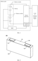
- FIG. 1 is a diagram of a structure of a battery pack according to an embodiment of this application.
- the battery pack may include one or more battery modules.
- FIG. 1 shows an example of a case in which the battery pack includes two battery modules.
- a plurality of battery modules are disposed in series, and battery modules located at two ends may be separately connected to a load, to form a discharging loop for discharging to the load.
- the battery modules located at the two ends may be separately connected to a charging power supply, to form a charging loop for charging each battery module.
- Each battery module may further include one or more batteries.
- FIG. 1 shows an example of a case in which each battery module includes two battery cells. Based on an energy storage requirement of an energy storage system, a plurality of batteries in the battery module may be connected in series, or may be connected in parallel. FIG. 1 shows a case in which the plurality of batteries are connected in series.
- the battery module may usually further include a busbar, and the plurality of batteries may be connected in series or in parallel through the busbar.
- the battery pack may usually further include a battery management system (BMS).
- BMS battery management system
- the BMS may monitor a status of the battery in real time, and may further learn of a status of the battery module, to cut off the charging loop/discharging loop in a timely manner when the battery module or the battery is faulty.
- a switch apparatus may be disposed in the charging loop/discharging loop of the battery pack, and a tripping device may be disposed in the switch apparatus.
- the BMS may control the tripping device in the switch apparatus to perform tripping, to disconnect the battery module from the load or the charging power supply, so as to cut off the charging loop/discharging loop.
- FIG. 2 is a diagram of a structure of a battery 100 according to an embodiment of this application.
- the battery 100 provided in this embodiment of this application includes, but is not limited to, a lithium-ion battery or a sodium-ion battery.
- the battery 100 may include a battery cover plate 110, a battery housing 120, and a battery core (not shown in the figure).
- the battery cover plate 110 and the battery housing 120 may be fastened to form a sealed cavity, and the battery core is disposed in the sealed cavity.
- the battery 100 provided in this embodiment of this application may be, but is not limited to, a regular-shaped battery, for example, a square battery or a round battery; and may be a possible irregular-shaped battery. This is not limited in this application.
- the square battery is used as an example for description.
- the battery cover plate 110 may include a cover plate body 111, and a first electrode assembly 112 and a second electrode assembly 113 that are disposed on the cover plate body.
- the first electrode assembly 112 and the second electrode assembly 113 may be a negative electrode assembly and a positive electrode assembly respectively.
- the first electrode assembly 112 may be electrically connected to a negative terminal of the battery core
- the second electrode assembly 113 may be electrically connected to a positive terminal of the battery core.
- FIG. 3 is a diagram of an exploded structure of the battery cover plate shown in FIG. 2 .
- the cover plate body 111 may be made of a conductive metal material, for example, including but not limited to aluminum or copper.
- the cover plate body 111 includes a first side and a second side that are opposite to each other. The first side of the cover plate body 111 faces an exterior of the battery 100, and the second side of the cover plate body 111 faces an interior of the battery 100.
- a first mounting hole 1111 and a second mounting hole 1112 are provided on the cover plate body 111, and the first mounting hole 1111 and the second mounting hole 1112 may extend from the first side of the cover plate body 111 to the second side of the cover plate body 111, to penetrate the cover plate body 111.
- the first electrode assembly 112 may include a first pole 1121 and a first conductive sheet 1122.
- the first pole 1121 may be disposed in the first mounting hole 1111, a first end of the first pole 1121 is electrically connected to the negative terminal of the battery core located inside the battery 100, and a second end of the first pole 1121 extends from the first side of the cover plate body 111 and is electrically connected to the first conductive sheet 1122 located on the first side of the cover plate body 111.
- the first pole 1121 and the first conductive sheet 1122 may be fastened and electrically connected through welding.
- the first conductive sheet 1122 may be configured for busbar connection, to implement a series connection or parallel connection between the battery 100 and another battery 100 in a same battery module.
- first pole 1121 and the negative terminal of the battery core may also be fastened and electrically connected through welding.
- a first connecting part 1123 may be disposed at the first end of the first pole 1121. In an extension direction perpendicular to the first pole 1121 (that is, a thickness direction of the cover plate body), a cross-sectional area of the first connecting part 1123 is greater than a cross-sectional area of the first pole 1121, so that a large welding surface can be implemented when the first pole 1121 is electrically connected to the battery core through the first connecting part 1123.
- the first pole 1121 and the first conductive sheet 1122 are separately insulated from the cover plate body 111.
- the first electrode assembly 112 may further include a first sealing ring 1124, and the first sealing ring 1124 is compressed and disposed between an outer wall of the first pole 1121 and an inner wall of the first mounting hole 1111.
- the first pole 1121 can be insulated from the cover plate body 111.
- sealing at the first mounting hole 1111 can be further implemented, to reduce a risk of electrolyte leakage through the first mounting hole 1111.
- the first electrode assembly 112 further includes a first insulating member 1125, and the first insulating member 1125 is disposed between the first conductive sheet 1122 and the cover plate body 111, to insulate the first conductive sheet 1122 from the cover plate body 111.
- a first avoidance hole 11251 may be provided at a position corresponding to the first mounting hole 1111 on the first insulating member 1125, so that the second end of the first pole 1121 may be electrically connected to the first conductive sheet 1122 through the first avoidance hole 11251.
- a first groove 11252 may be provided on a surface that is of the first insulating member 1125 and that faces away from the cover plate body 111, and the first conductive sheet 1122 may be embedded in the first groove 11252, to improve mounting reliability of the first conductive sheet 1122 on the first insulating member 1125.
- a material of the first insulating member 1125 includes but is not limited to plastic, and a resistance value of the first insulating member 1125 may not be less than 200 mQ@500 V. In other words, in a test condition in which a voltage is 500 V, the resistance value of the first insulating member 1125 is 200 mQ or above.
- the second electrode assembly 113 may include a second pole 1131 and a second conductive sheet 1132.
- the second pole 1131 may be disposed in the second mounting hole 1112, a first end of the second pole 1131 is electrically connected to the positive terminal of the battery core located inside the battery 100, and a second end of the second pole 1131 extends from the first side of the cover plate body 111 and is electrically connected to the second conductive sheet 1132 located on the first side of the cover plate body 111.
- the second pole 1131 and the second conductive sheet 1132 may be fastened and electrically connected through welding.
- the second conductive sheet 1132 may be configured for busbar connection, to implement the series connection or parallel connection between the battery 100 and the another battery in the same battery module.
- the second pole 1131 and the positive terminal of the battery core may also be fastened and electrically connected through welding.
- a second connecting part 1133 may be disposed at the first end of the second pole 1131.
- a cross-sectional area of the second connecting part 1133 is greater than a cross-sectional area of the second pole 1131, so that a large welding surface can be implemented when the second pole 1131 is electrically connected to the battery core through the second connecting part 1133.
- the second pole 1131 and the second conductive sheet 1132 are also separately insulated from the cover plate body 111.
- the second electrode assembly 113 may further include a second sealing ring 1134, and the second sealing ring 1134 is compressed and disposed between an outer wall of the second pole 1131 and an inner wall of the second mounting hole 1112, so that the second pole 1131 can be insulated from the cover plate body 111, and sealing at the second mounting hole 1112 can be implemented, to reduce a risk of electrolyte leakage through the second mounting hole 1112.
- the second electrode assembly 113 may further include a second insulating member 1135, and the second insulating member 1135 is disposed between the second conductive sheet 1132 and the cover plate body 111, to insulate the second conductive sheet 1132 from the cover plate body 111.
- a second avoidance hole 11351 may be provided at a position corresponding to the second mounting hole 1112 on the second insulating member 1135, so that the second end of the second pole 1131 can be electrically connected to the second conductive sheet 1132 through the second avoidance hole 11351.
- a second groove 11352 may also be provided on a surface that is of the second insulating member 1135 and that faces away from the cover plate body 111, and the second conductive sheet 1132 may be embedded in the second groove 11352, to improve mounting reliability of the second conductive sheet 1132 on the second insulating member 1135.
- a material of the second insulating member 1135 includes but is not limited to plastic, and a resistance value of the second insulating member 1135 may not be less than 200 mQ@500 V.
- the battery cover plate 110 may further include a third insulating member 1136.
- the third insulating member 1136 is approximately the same as the cover plate body 111 in shape, and is attached to the second side of the cover plate body 111.
- a third avoidance hole 11361 may be provided at a position corresponding to the first mounting hole 1111 on the third insulating member 1136, and a fourth avoidance hole 11362 may be provided at a position corresponding to the second mounting hole 1112.
- the first connecting part 1123 is located on a side that is of the third insulating member 1136 and that faces away from the cover plate body 111, to insulate the first connecting part 1123 from the cover plate body 111 by using the third insulating member 1136.
- the first pole 1121 may sequentially pass through the third avoidance hole 11361, the first mounting hole 1111, and the first avoidance hole 11251 to be connected to the first conductive sheet 1122.
- the second connecting part 1133 is located on the side that is of the third insulating member 1136 and that faces away from the cover plate body 111, to insulate the second connecting part 1133 from the cover plate body 111 by using the third insulating member 1136.
- the second pole 1131 may sequentially pass through the fourth avoidance hole 11362, the second mounting hole 1112, and the second avoidance hole 11351 to be connected to the second conductive sheet 1132.
- a material of the third insulating member 1136 includes but is not limited to plastic, and a resistance value of the third insulating member 1136 may not be less than 200 mQ@500 V.
- an explosion-proof valve may be further disposed on the battery cover plate 110.
- the explosion-proof valve When the battery 100 is faulty and the pressure inside the battery 100 is greater than turning-on pressure of the explosion-proof valve, the explosion-proof valve is turned on, to exhaust the gas inside the battery 100, so as to reduce a temperature of the battery 100, release the pressure, and prevent the battery 100 from further experiencing a more serious safety problem, for example, explosion.
- a first through hole 1113 that communicates the interior and the exterior of the battery 100 may be further provided on the cover plate body 111, and the explosion-proof valve 114 may be welded and fastened on a surface on one side of the cover plate body 111, to block the first through hole 1113.
- the explosion-proof valve 114 may be disposed on the first side of the cover plate body 111, or may be disposed on the second side of the cover plate body 111. This is not limited in this application, provided that the first through hole 1113 can be blocked.
- a fifth avoidance hole 11363 may be provided at a position corresponding to the first through hole 1113 on the third insulating member 1136, so that the pressure inside the battery 100 can directly act on the explosion-proof valve 114 through the fifth avoidance hole 11363.
- FIG. 4 is a diagram of a structure of the explosion-proof valve 114 according to an embodiment of this application.
- a notch 1141 is provided on a surface of the explosion-proof valve 114. Because a thickness at the notch 1141 is less than a thickness at another position of the explosion-proof valve 114, structural strength at the notch 1141 is also less than structural strength at the another position. In other words, a position at which the notch 1141 is located is a weak point of the explosion-proof valve 114. Under the action of the pressure inside the battery, when the explosion-proof valve 114 ruptures along the notch 1141, it is considered that the explosion-proof valve 114 is turned on.
- the notch 1141 may be provided on a surface on a side that is of the explosion-proof valve 114 and that faces the interior of the battery, or may be provided on a surface on a side that is of the explosion-proof valve 114 and that faces away from the interior of the battery. This is not limited in this application. During specific implementation, the notch 1141 may be formed by using a stamping process.
- a thickness (that is, a residual thickness) at a position corresponding to the notch on the explosion-proof valve 114 may be greater than or equal to 50 ⁇ m and less than or equal to 300 ⁇ m, to ensure processability of the explosion-proof valve 114, and reduce impact of a fluctuation of the residual thickness during processing on the turning-on pressure of the explosion-proof valve 114.
- the thickness at the position corresponding to the notch 1141 on the explosion-proof valve 114 may be 50 ⁇ m, 100 ⁇ m, 200 ⁇ m, 300 ⁇ m, or the like.
- a projection of the notch 1141 on the surface of the cover plate body 111 may be located in a region defined by the first through hole 1113, and the notch 1141 may define a fastening part 1143 and a flippable part 1142 on the explosion-proof valve 114.
- a peripheral side of the flippable part 1142 has a connecting side connected to the fastening part 1143, and a position, on the peripheral side of the flippable part 1142, other than the connecting side may be separated from the fastening part 1143 by the notch.
- the notch 1141 ruptures, so that the flippable part 1142 is flipped along the notch, and the first through hole 1113 is opened. It may be understood that an axis around which the flippable part 1142 is flipped is an extension line of the connecting side of the flippable part 1142. When the flippable part 1142 is flipped along the notch, the connecting side of the flippable part 1142 continues to remain connected to the fastening part 1143. Therefore, after the explosion-proof valve 114 is turned on, the flippable part 1142 does not fall off from the explosion-proof valve 114.
- FIG. 5 is a diagram of several possible plane structures of the explosion-proof valve 114 according to an embodiment of this application.
- a shape of the explosion-proof valve 114 may be a circle, a racetrack shape, a semicircle, a rectangle, or the like, as shown in FIG. 5 ; or may be another regular or irregular shape. This is not specifically limited in this application.
- a material of the explosion-proof valve 114 may be a metal having a specific deformation capability, for example, aluminum or copper.
- a shape of the flippable part 1142 may be designed based on the shape of the explosion-proof valve 114.
- the shape of the flippable part 1142 may also be approximately the circle, the racetrack shape, the semicircle, the rectangle, or the like. This helps increase an extension length of the notch 1141, in other words, increase an area of the flippable part 1142, so that after the flippable part 1142 is flipped, the pressure inside the battery can be quickly released.
- the shape of the flippable part 1142 may alternatively be designed as another regular or irregular open ring shape.
- the extension length of the notch 1141 may be greater than or equal to 0.6C and less than or equal to 0.8C.
- the extension length of the notch 1141 may be 0.6C, 0.7C, or 0.8C.
- FIG. 6 is a diagram of a cross-sectional structure of the battery cover plate 110 according to an embodiment of this application.
- FIG. 7 is a diagram of a cross-sectional structure of the battery cover plate 110 shown in FIG. 6 after the explosion-proof valve 114 is turned on.
- a projection of an outer contour of the first insulating member 1125 on the surface of the cover plate body 111 may cover the first through hole 1113.
- a projection region of lines forming an outer edge of the first insulating member 1125 on the surface of the cover plate body 111 covers the first through hole 1113.
- a slot 11254 may be provided on a first side wall 11253 of the first insulating member 1125, the slot 11254 penetrates the first insulating member 1125 in a thickness direction of the first insulating member 1125, and the slot 11254 may communicate with the first through hole 1113, to expose the explosion-proof valve 114.
- the first conductive sheet 1122 may partially or completely cover the slot 11254.
- the flippable part 1142 of the explosion-proof valve 114 is flipped toward the first side of the cover plate body 111 under the action of the pressure, so that the flippable part 1142 extends into the slot 11254 and is in contact with the first conductive sheet 1122 located above the first insulating member 1125.
- an exhaust vent having a consistent shape with the flippable part 1142 is formed on the explosion-proof valve 114, and the gas inside the battery may be exhausted to the exterior of the battery sequentially through the first through hole 1113, the exhaust vent of the explosion-proof valve 114, and the slot 11254, to release the pressure and prevent the battery from further experiencing a more serious safety problem, for example, explosion.
- a more serious safety problem for example, explosion.
- the first conductive sheet 1122 does not completely cover the slot 11254
- some gas may be further exhausted through a region that is not covered by the slot 11254. This helps improve a gas exhaust rate and reduce duration used to release the pressure.
- the first through hole 1113 may be a tapered hole, and a diameter of the first through hole 1113 gradually decreases in a direction from the first side of the cover plate body 111 to the second side of the cover plate body 111.
- a surface on a side that is of the flippable part 1142 and that faces the interior of the battery is inclined relative to the surface of the cover plate body 111.
- a diversion channel may be formed between an inner wall of the first through hole 1113 and the surface on the side that is of the flippable part 1142 and that faces the interior of the battery.
- a diversion function of the diversion channel on the gas in a gas exhaust process can be used to effectively improve the gas exhaust rate.
- the connecting side of the flippable part 1142 may be disposed away from the first side wall 11253 of the first insulating member 1125.
- an end part of the diversion channel formed by the flippable part 1142 and the first through hole 1113 faces the first side wall 11253. This disposition can shorten a gas exhaust path, and therefore help further improve the gas exhaust rate.
- FIG. 6 and FIG. 7 Before the flippable part 1142 of the explosion-proof valve 114 is flipped, there is no electrical connection relationship between the explosion-proof valve 114 and either the first electrode assembly 112 or the second electrode assembly 113. After the flippable part 1142 of the explosion-proof valve 114 is flipped, the flippable part 1142 is in contact with the first conductive sheet 1122 above to implement an electrical connection.
- an opening side of the flippable part 1142 continues to remain connected to the fastening part 1143 of the explosion-proof valve 114, and the fastening part 1143 of the explosion-proof valve 114 also remains connected to the cover plate body 111, an electrical connection relationship is established between the first conductive sheet 1122 and the cover plate body 111, in other words, an electrical connection between the first electrode assembly 112 and the cover plate body 111 is implemented.
- a protrusion 1144 may be provided on a surface that is of the flippable part 1142 and that faces the first side of the cover plate body 111, and the protrusion 1144 is located on a side that is of the flippable part 1142 and that is away from the opening side. After the flippable part 1142 is flipped, the side that is of the flippable part 1142 and that is away from the opening side is closer to the first conductive sheet 1122. Therefore, the protrusion 1144 is provided on the side to facilitate easier contact with the first conductive sheet 1122, and therefore implement the electrical connection to the first conductive sheet 1122.
- a surface on a side that is of the protrusion 1144 and that is away from the flippable part 1142 may be an arc-shaped surface. In this way, reliability of contact between the protrusion 1144 and the first conductive sheet 1122 can be ensured.
- the protrusion 1144 may include a first section 11441 and a second section 11442.
- the first section 11441 is provided on a surface of the flippable part 1142
- the second section 11442 is provided on a side that is of the first section 11441 and that is away from the flippable part 1142
- the first section 11441 may be in a columnar structure, for example, a cylindrical structure
- the second section 11442 may be in a hemisphere structure.
- a height of the first section 11441 may be greater than or equal to 0.1 mm and less than or equal to 10 mm
- a radius of the second section 11442 may be greater than or equal to 0.1 mm and less than or equal to 10 mm.
- the height of the first section 11441 may be 0.1 mm, 1 mm, 7 mm, 10 mm, or the like; and the radius of the second section 11442 may be 0.1 mm, 2 mm, 5 mm, 7 mm, or the like.
- the cover plate body 111 is uncharged.
- a voltage between the second electrode assembly 113 and the cover plate body 111 is a voltage of the second electrode assembly 113.
- the cover plate body 111 is electrically connected to the first electrode assembly 112, and potentials of the cover plate body 111 and the first electrode assembly 112 are the same.
- the voltage between the second electrode assembly 113 and the cover plate body 111 is a voltage between the second electrode assembly 113 and the first electrode assembly 112. Based on this, in this embodiment, whether the explosion-proof valve is turned on can be determined by detecting the voltage between the second electrode assembly 113 and the cover plate body 111.
- a material of the conducting wire in the detection loop includes, but is not limited to, one or more of metals such as gold, silver, copper, iron, zinc, tin, aluminum, magnesium, cobalt, nickel, manganese, platinum, tantalum, tungsten, rhenium, osmium, iridium, palladium, ruthenium, zirconium, molybdenum, vanadium, titanium, and scandium.
- metals such as gold, silver, copper, iron, zinc, tin, aluminum, magnesium, cobalt, nickel, manganese, platinum, tantalum, tungsten, rhenium, osmium, iridium, palladium, ruthenium, zirconium, molybdenum, vanadium, titanium, and scandium.
- the BMS may be specifically configured to: when the detected voltage of the voltage detection circuit jumps to a first voltage, determine that the flippable part 1142 of the explosion-proof valve 114 is flipped, that is, determine that the explosion-proof valve 114 is turned on.
- the first voltage herein is the voltage between the second electrode assembly 113 and the first electrode assembly 112.
- the battery pack may further include an alarm.
- the BMS is connected to the alarm, and may be configured to control the alarm to give an early warning after determining that the explosion-proof valve 114 is turned on.
- the BMS may be configured to cut off an internal loop of the battery core of the battery based on the warning sent by the alarm.
- the BMS may further control, based on the warning sent by the alarm, the tripping device in the switch apparatus to perform tripping, to cut off the charging loop/discharging loop of the battery pack, so as to facilitate offline maintenance.
Landscapes
- Chemical & Material Sciences (AREA)
- Chemical Kinetics & Catalysis (AREA)
- Electrochemistry (AREA)
- General Chemical & Material Sciences (AREA)
- Engineering & Computer Science (AREA)
- Manufacturing & Machinery (AREA)
- Gas Exhaust Devices For Batteries (AREA)
- Sealing Battery Cases Or Jackets (AREA)
Applications Claiming Priority (2)
| Application Number | Priority Date | Filing Date | Title |
|---|---|---|---|
| CN202222714190.6U CN219436069U (zh) | 2022-10-09 | 2022-10-09 | 一种电池盖板、电池、电池包及储能系统 |
| PCT/CN2023/102170 WO2024078008A1 (zh) | 2022-10-09 | 2023-06-25 | 一种电池盖板、电池、电池包及储能系统 |
Publications (2)
| Publication Number | Publication Date |
|---|---|
| EP4576376A1 true EP4576376A1 (de) | 2025-06-25 |
| EP4576376A4 EP4576376A4 (de) | 2025-12-03 |
Family
ID=87346357
Family Applications (1)
| Application Number | Title | Priority Date | Filing Date |
|---|---|---|---|
| EP23876218.1A Pending EP4576376A4 (de) | 2022-10-09 | 2023-06-25 | Batterieabdeckplatte, batterie, batteriepack und energiespeichersystem |
Country Status (3)
| Country | Link |
|---|---|
| EP (1) | EP4576376A4 (de) |
| CN (1) | CN219436069U (de) |
| WO (1) | WO2024078008A1 (de) |
Families Citing this family (4)
| Publication number | Priority date | Publication date | Assignee | Title |
|---|---|---|---|---|
| CN118572296B (zh) * | 2024-08-01 | 2024-10-22 | 惠州市瑞能德电子有限公司 | 一种锂离子电池储能模组 |
| CN118589163B (zh) * | 2024-08-06 | 2024-12-10 | 比亚迪股份有限公司 | 一种集流组件、电池单体、电池包和用电设备 |
| CN118867556B (zh) * | 2024-09-27 | 2025-01-21 | 蜂巢能源科技股份有限公司 | 电芯外壳及电芯 |
| CN120149679B (zh) * | 2025-03-14 | 2025-12-02 | 蜂巢能源科技股份有限公司 | 一种电池 |
Family Cites Families (7)
| Publication number | Priority date | Publication date | Assignee | Title |
|---|---|---|---|---|
| JP3693844B2 (ja) * | 1999-03-01 | 2005-09-14 | アルプス電気株式会社 | 電池の感圧電路遮断機構 |
| KR101666256B1 (ko) * | 2013-01-09 | 2016-10-13 | 삼성에스디아이 주식회사 | 이차 전지 |
| US10008710B2 (en) * | 2014-08-04 | 2018-06-26 | Johnson Controls Technology Company | Overcharge protection assembly for a battery module |
| CN112952303B (zh) * | 2018-04-23 | 2023-07-11 | 比亚迪股份有限公司 | 电池盖板组件、电池、电池模组、动力电池和电动汽车 |
| CN208111497U (zh) * | 2018-04-26 | 2018-11-16 | 东莞百思利新能源科技有限公司 | 二次电池顶盖及其二次电池 |
| CN216958400U (zh) * | 2021-11-30 | 2022-07-12 | 桑顿新能源科技有限公司 | 一种动力电池防爆装置及动力电池 |
| CN216793925U (zh) * | 2022-04-06 | 2022-06-21 | 四川新能源汽车创新中心有限公司 | 一种电池防爆结构 |
-
2022
- 2022-10-09 CN CN202222714190.6U patent/CN219436069U/zh active Active
-
2023
- 2023-06-25 EP EP23876218.1A patent/EP4576376A4/de active Pending
- 2023-06-25 WO PCT/CN2023/102170 patent/WO2024078008A1/zh not_active Ceased
Also Published As
| Publication number | Publication date |
|---|---|
| CN219436069U (zh) | 2023-07-28 |
| EP4576376A4 (de) | 2025-12-03 |
| WO2024078008A1 (zh) | 2024-04-18 |
Similar Documents
| Publication | Publication Date | Title |
|---|---|---|
| CN219436069U (zh) | 一种电池盖板、电池、电池包及储能系统 | |
| EP3422441B1 (de) | Einzellige batterie, batteriemodul, batteriepack und elektrisches fahrzeug | |
| EP3322001B1 (de) | Sekundärbatterie und batteriemodul | |
| RU2468477C2 (ru) | Аккумуляторная батарея среднего или большого размера повышенной безопасности | |
| KR100764618B1 (ko) | 안전장치를 구비하고 있는 이차전지 | |
| EP3419084B1 (de) | Einzellige batterie, batteriemodul, leistungsbatterie und elektrofahrzeug | |
| JP5806262B2 (ja) | 電流遮断装置及びそれを用いた蓄電装置 | |
| US6063518A (en) | Sealed electrochemical cell equipped with a circuit-breaking terminal | |
| KR20150038077A (ko) | 서멀 스위치를 가진 배터리 | |
| EP3422440B1 (de) | Einzellige batterie, batteriemodul, hochleistungsbatterie und elektrisches fahrzeug | |
| JP2008234903A (ja) | 電池及び電池システム | |
| CN105190947B (zh) | 具有可复位的安全装置的蓄电池及用于其的合适极柱螺栓 | |
| EP3726618A1 (de) | Batterieabdeckungsplattenanordnung, einzelzellenbatterie, batteriemodul, leistungsbatterie und elektrofahrzeug | |
| JP5796067B2 (ja) | 円筒型二次電池及び電池システム | |
| KR20170024842A (ko) | 전지 모듈 | |
| US8993139B2 (en) | Sealed secondary battery | |
| CN106458038B (zh) | 运行蓄能单元的方法、实施这种方法的电池管理系统 | |
| US8685555B2 (en) | Thermo-mechanically activated current interrupter | |
| KR102335696B1 (ko) | 전류차단부재 및 캡 조립체 | |
| US20260048681A1 (en) | Battery management system including wake-up function and battery management system wake-up method | |
| EP3726619A1 (de) | Stromunterbrechungsvorrichtung und wendeelement hierfür, batterieabdeckplattenanordnung, einzelzelle, batteriemodul, batterie und elektrisches fahrzeug | |
| US20240072399A1 (en) | Disconnection device and short-circuiting device comprising a heat-activatable element | |
| CN222654018U (zh) | 一种带内置bms板的圆柱锂电池正负极连接装置 | |
| KR100277652B1 (ko) | 이차전지의 캡 어셈블리 | |
| JP2014235943A (ja) | 二次電池 |
Legal Events
| Date | Code | Title | Description |
|---|---|---|---|
| STAA | Information on the status of an ep patent application or granted ep patent |
Free format text: STATUS: THE INTERNATIONAL PUBLICATION HAS BEEN MADE |
|
| PUAI | Public reference made under article 153(3) epc to a published international application that has entered the european phase |
Free format text: ORIGINAL CODE: 0009012 |
|
| STAA | Information on the status of an ep patent application or granted ep patent |
Free format text: STATUS: REQUEST FOR EXAMINATION WAS MADE |
|
| 17P | Request for examination filed |
Effective date: 20250318 |
|
| AK | Designated contracting states |
Kind code of ref document: A1 Designated state(s): AL AT BE BG CH CY CZ DE DK EE ES FI FR GB GR HR HU IE IS IT LI LT LU LV MC ME MK MT NL NO PL PT RO RS SE SI SK SM TR |
|
| A4 | Supplementary search report drawn up and despatched |
Effective date: 20251031 |
|
| RIC1 | Information provided on ipc code assigned before grant |
Ipc: H01M 50/342 20210101AFI20251027BHEP Ipc: H01M 50/569 20210101ALI20251027BHEP Ipc: H01M 50/15 20210101ALI20251027BHEP Ipc: H01M 10/42 20060101ALI20251027BHEP Ipc: H01M 50/176 20210101ALI20251027BHEP Ipc: H01M 10/48 20060101ALI20251027BHEP |
|
| DAV | Request for validation of the european patent (deleted) | ||
| DAX | Request for extension of the european patent (deleted) |