EP4576414A1 - Elektrolytlösungs-injektionsverfahren und elektrolytlösungs-injektionsvorrichtung - Google Patents
Elektrolytlösungs-injektionsverfahren und elektrolytlösungs-injektionsvorrichtung Download PDFInfo
- Publication number
- EP4576414A1 EP4576414A1 EP23855190.7A EP23855190A EP4576414A1 EP 4576414 A1 EP4576414 A1 EP 4576414A1 EP 23855190 A EP23855190 A EP 23855190A EP 4576414 A1 EP4576414 A1 EP 4576414A1
- Authority
- EP
- European Patent Office
- Prior art keywords
- injecting
- electrolyte
- secondary battery
- compressing
- injecting part
- Prior art date
- Legal status (The legal status is an assumption and is not a legal conclusion. Google has not performed a legal analysis and makes no representation as to the accuracy of the status listed.)
- Pending
Links
Images


Classifications
-
- H—ELECTRICITY
- H01—ELECTRIC ELEMENTS
- H01M—PROCESSES OR MEANS, e.g. BATTERIES, FOR THE DIRECT CONVERSION OF CHEMICAL ENERGY INTO ELECTRICAL ENERGY
- H01M50/00—Constructional details or processes of manufacture of the non-active parts of electrochemical cells other than fuel cells, e.g. hybrid cells
- H01M50/60—Arrangements or processes for filling or topping-up with liquids; Arrangements or processes for draining liquids from casings
- H01M50/609—Arrangements or processes for filling with liquid, e.g. electrolytes
- H01M50/618—Pressure control
-
- H—ELECTRICITY
- H01—ELECTRIC ELEMENTS
- H01M—PROCESSES OR MEANS, e.g. BATTERIES, FOR THE DIRECT CONVERSION OF CHEMICAL ENERGY INTO ELECTRICAL ENERGY
- H01M50/00—Constructional details or processes of manufacture of the non-active parts of electrochemical cells other than fuel cells, e.g. hybrid cells
- H01M50/60—Arrangements or processes for filling or topping-up with liquids; Arrangements or processes for draining liquids from casings
- H01M50/609—Arrangements or processes for filling with liquid, e.g. electrolytes
- H01M50/627—Filling ports
-
- Y—GENERAL TAGGING OF NEW TECHNOLOGICAL DEVELOPMENTS; GENERAL TAGGING OF CROSS-SECTIONAL TECHNOLOGIES SPANNING OVER SEVERAL SECTIONS OF THE IPC; TECHNICAL SUBJECTS COVERED BY FORMER USPC CROSS-REFERENCE ART COLLECTIONS [XRACs] AND DIGESTS
- Y02—TECHNOLOGIES OR APPLICATIONS FOR MITIGATION OR ADAPTATION AGAINST CLIMATE CHANGE
- Y02E—REDUCTION OF GREENHOUSE GAS [GHG] EMISSIONS, RELATED TO ENERGY GENERATION, TRANSMISSION OR DISTRIBUTION
- Y02E60/00—Enabling technologies; Technologies with a potential or indirect contribution to GHG emissions mitigation
- Y02E60/10—Energy storage using batteries
Definitions
- the present invention relates to a method and apparatus for injecting an electrolyte, which injects the electrolyte into a battery case.
- aAn apparatus for injecting an electrolyte may include: a chamber that accommodates the secondary battery therein; an injecting part that stores the electrolyte therein and injects the electrolyte into the secondary battery through a difference in pressure between the inside thereof and the inside of the chamber; and a compressing part that is connected to the injecting part and compresses the inside of the injecting part so as to inject the electrolyte remaining in the injecting part into the secondary battery.
- the apparatus for injecting the electrolyte may further include an injection passage that allows the injecting part and the secondary battery to communicate with each other, and adjusts opening or closing.
- the compressing part may press the pneumatic space so as to allow the electrolyte remaining in the injecting part to flow into the secondary battery.
- the electrolyte remaining in the injecting part may be additionally injected into the secondary battery to prevent the problems that due to the remaining electrolyte, the injection efficiency is deteriorated, and the injecting apparatus corrodes.
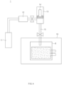
- FIG. 3 is a schematic view of an apparatus 1 for injecting an electrolyte according to an embodiment of the present invention.
- the apparatus 1 for injecting the electrolyte may inject the electrolyte into a secondary battery.
- the secondary battery may include a battery case and an electrode assembly accommodated in the battery case, and the electrolyte may be injected into the battery case in order to activate the electrode assembly.
- the electrolyte stored in the apparatus 1 for injecting the electrolyte may flow into the battery case through a difference in pressure between the inside of the apparatus 1 for injecting the electrolyte and the inside of the battery case.
- the apparatus 1 for injecting the electrolyte may also additionally inject, into the secondary battery, the electrolyte remaining in the inside thereof after injecting the electrolyte through the different in pressure.
- the apparatus 1 for injecting the electrolyte may inject the electrolyte and then, compress the inside thereof so as to additionally inject the electrolyte remaining in the inside into the secondary battery.
- the apparatus 1 for injecting the electrolyte may include a chamber 10, an injecting part 13, and a compressing part 14.
- the apparatus 1 for injecting the electrolyte may further include an injection passage 15.
- the chamber 10 may define an accommodating space therein and accommodate the secondary battery therein.
- the chamber 10 may be connected to a vacuum pump to change the inside thereof into a vacuum state and maintain the vacuum state through the vacuum pump. That is, for an injection operation of the injecting part 13 to be described later, the chamber 10 may function to change the inside thereof into the vacuum state so that the electrolyte is injected into the secondary battery.
- the injecting part 13 may communicate with the secondary battery and inject the electrolyte into the secondary battery.
- the injecting part 13 may store the electrolyte therein, and inject the electrolyte into the secondary battery through a difference in pressure between the inside thereof and the inside of the chamber 10.
- the inside of the injecting part 13 and the inside of the secondary battery may communicate with each other through the injection passage 15.
- the injection passage 15 may adjust opening or closing in a state of allowing the inside of the injecting part 13 and the inside of the secondary battery to communicate with each other.
- the injection passage 15 may include a switching valve to adjust opening or closing of a passage so that when the inside of the chamber 10 reaches a vacuum state and is maintained in the vacuum state, the injection passage 15 functions to open the passage and allow the electrolyte in the injecting part 13 to flow into the secondary battery.
- the apparatus 1 for injecting the electrolyte may further include a storing part 11 that stores the electrolyte, and a pump 12 that allows the electrolyte in the storing part 11 to flow into the injecting part 13.
- the pump 12 may include a Hibar pump.
- the pump 12 may suction a fluid by generating an internal negative pressure through a retreating plunger member to open a valve of an inlet, and discharge the fluid to the outside by advancing the plunger to open a valve of an outlet.
- the type of the pump 12 is not limited thereto.
- the pump 12 may supply the electrolyte to the injecting part 13 by allowing the electrolyte stored in the storing part 11 to flow into the injecting part 13.
- a pneumatic space 130 may be defined in the injecting part 13.
- the pneumatic space 130 may be defined between the electrolyte and the compressing part 14.
- the electrolyte may flow from the inside of the injecting part 13 into the secondary battery through the difference in pressure between the inside of the injecting part 13 and the inside of the chamber 10 as described above, and the pressures between the inside of the injecting part 13 and the inside of the chamber 10 may be in equilibrium.
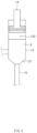
- FIG. 4 is a schematic view of a state in which the compressing part 14 compresses the inside of the injecting part 13 according to an embodiment of the present invention.
- the compressing part 14 may compress the inside of the injecting part 13 so as to inject the electrolyte remaining in the injecting part 13 into the secondary battery.
- the compressing part 14 may be connected to one side of the injecting part 13 so as to compress an inner space of the injecting part 13.
- the compressing part 14 may push the electrolyte remaining in the injecting part 13 and inject the electrolyte into the secondary battery, through a separate compressing operation.
- the compressing part 14 may press the pneumatic space 130 to allow the electrolyte remaining in the injecting part 13 to flow into the secondary battery. More specifically, in a state in which the injection passage 15 is provided in one surface of the injecting part 13, and the compressing part 14 is connected to the other surface of the injecting part 13, the compressing part 14 may perform the compressing operation of descending toward the one surface of the injecting part 13. That is, the compressing part 14 may press an upper side of the pneumatic space 130 to compress the inside of the injecting part 13 so that the electrolyte remaining in the injecting part 13 is pushed by the pneumatic space 130 to flow and be discharged along the injection passage 15 provided in a lower side of the injecting part 13.
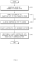
- the electrolyte may be injected into the secondary battery through a difference in pressure between the inside of the chamber 10 that is in the vacuum state and the inside of the injecting part 13 in which the electrolyte is stored.
- the inside of the injecting part 13 and the inside of the secondary battery may communicate with each other through an injection passage 15.
- the injection passage 15 may adjust opening or closing in a state of allowing the inside of the injecting part 13 and the inside of the secondary battery to communicate with each other.
- the compressing part 14 connected to the injecting part 13 may compress the inside of the injecting part 13 so as to inject the electrolyte into the secondary battery.
- the compressing part 14 may be connected to one side of the injecting part 13 so as to compress an inner space of the injecting part 13.
- the compressing part 14 may push the electrolyte remaining in the injecting part 13 and inject the electrolyte into the secondary battery, through a separate compressing operation.
- the compressing part 14 may press the pneumatic space 130 to allow the electrolyte remaining in the injecting part 13 to flow into the secondary battery.
Landscapes
- Chemical & Material Sciences (AREA)
- Chemical Kinetics & Catalysis (AREA)
- Electrochemistry (AREA)
- General Chemical & Material Sciences (AREA)
- Filling, Topping-Up Batteries (AREA)
Applications Claiming Priority (2)
| Application Number | Priority Date | Filing Date | Title |
|---|---|---|---|
| KR1020220104378A KR20240026021A (ko) | 2022-08-19 | 2022-08-19 | 전해액 주입 방법 및 전해액 주입 장치 |
| PCT/KR2023/012283 WO2024039224A1 (ko) | 2022-08-19 | 2023-08-18 | 전해액 주입 방법 및 전해액 주입 장치 |
Publications (2)
| Publication Number | Publication Date |
|---|---|
| EP4576414A1 true EP4576414A1 (de) | 2025-06-25 |
| EP4576414A4 EP4576414A4 (de) | 2025-12-10 |
Family
ID=89941985
Family Applications (1)
| Application Number | Title | Priority Date | Filing Date |
|---|---|---|---|
| EP23855190.7A Pending EP4576414A4 (de) | 2022-08-19 | 2023-08-18 | Elektrolytlösungs-injektionsverfahren und elektrolytlösungs-injektionsvorrichtung |
Country Status (5)
| Country | Link |
|---|---|
| EP (1) | EP4576414A4 (de) |
| KR (1) | KR20240026021A (de) |
| CN (1) | CN223680354U (de) |
| DE (1) | DE212023000311U1 (de) |
| WO (1) | WO2024039224A1 (de) |
Family Cites Families (8)
| Publication number | Priority date | Publication date | Assignee | Title |
|---|---|---|---|---|
| KR101222324B1 (ko) * | 2006-03-09 | 2013-01-16 | 삼성에스디아이 주식회사 | 고속 전해액 주입 장치의 주액 헤드 |
| KR101222337B1 (ko) * | 2006-03-09 | 2013-01-16 | 삼성에스디아이 주식회사 | 전해액 주입 장치 |
| KR101002783B1 (ko) * | 2010-05-27 | 2011-01-10 | (주)벡셀 | 전해액 주입방법 |
| KR102234989B1 (ko) * | 2016-07-21 | 2021-04-01 | 주식회사 엘지화학 | 각형 전지의 전해액 주입장치 및 이를 이용한 전해액 주입 방법 |
| CN106711489B (zh) * | 2016-12-28 | 2019-09-03 | 宁德时代新能源科技股份有限公司 | 软包电池的加工装置 |
| KR102586807B1 (ko) * | 2017-11-24 | 2023-10-10 | (주)이티에스 | 전해질 주입장치 및 전해액 주입방법 |
| WO2019147075A1 (ko) * | 2018-01-26 | 2019-08-01 | (주)엔에스 | 주입 노즐 어셈블리와, 이를 이용한 이차전지 제조 장치 및 방법 |
| KR102504916B1 (ko) | 2021-01-18 | 2023-03-02 | 제트스타 주식회사 | 써레 안전장치 |
-
2022
- 2022-08-19 KR KR1020220104378A patent/KR20240026021A/ko active Pending
-
2023
- 2023-08-18 CN CN202390000500.8U patent/CN223680354U/zh active Active
- 2023-08-18 WO PCT/KR2023/012283 patent/WO2024039224A1/ko not_active Ceased
- 2023-08-18 EP EP23855190.7A patent/EP4576414A4/de active Pending
- 2023-08-18 DE DE212023000311.2U patent/DE212023000311U1/de active Active
Also Published As
| Publication number | Publication date |
|---|---|
| KR20240026021A (ko) | 2024-02-27 |
| DE212023000311U1 (de) | 2025-04-24 |
| CN223680354U (zh) | 2025-12-16 |
| WO2024039224A1 (ko) | 2024-02-22 |
| EP4576414A4 (de) | 2025-12-10 |
Similar Documents
| Publication | Publication Date | Title |
|---|---|---|
| KR100868684B1 (ko) | 전지용 전해액 주입 장치 및 이를 이용한 전해액 주입 방법 | |
| KR101748362B1 (ko) | 파우치형 이차 전지 제조 방법 | |
| KR101780786B1 (ko) | 전해액 주입 장치 및 주입 방법 | |
| EP2978050B1 (de) | Batterie mit einem gasentladungselement und einem elektrolyteinspritzelement | |
| KR102586807B1 (ko) | 전해질 주입장치 및 전해액 주입방법 | |
| CN1182614C (zh) | 密闭型蓄电池 | |
| KR101508400B1 (ko) | 전해액 충전용 이차전지 | |
| KR102084595B1 (ko) | 주입 노즐 어셈블리 | |
| KR100804522B1 (ko) | 이차전지의 제조방법 | |
| KR20150045097A (ko) | 파우치형 리튬 이차전지의 제조 방법 | |
| KR20220046163A (ko) | 이차 전지 셀의 가스제거 장치 | |
| KR102177819B1 (ko) | 각형 이차전지의 제조 방법 및 제조 장치 | |
| EP4576414A1 (de) | Elektrolytlösungs-injektionsverfahren und elektrolytlösungs-injektionsvorrichtung | |
| CN118198518A (zh) | 用于全固态电池的加压系统 | |
| KR102752773B1 (ko) | 밑면에 개폐부가 형성된 원통형 이차전지 | |
| KR102710217B1 (ko) | 이차전지용 프리차저 | |
| EP4167330B1 (de) | Sekundärbatterie und verfahren zur herstellung | |
| CN114204233A (zh) | 采用多边形双孔注液方式的锂离子电池注液方法 | |
| KR20170093369A (ko) | 조절 가능한 밸브를 이용한 전지셀의 탈기 장치 및 이를 이용한 탈기 방법 | |
| KR20200065509A (ko) | 전해액 함침 장치 및 전해액 함침 방법 | |
| KR100822192B1 (ko) | 전해액 주입방법 | |
| US20220271323A1 (en) | Degassing device for preparing secondary battery | |
| JP4295477B2 (ja) | 二次電池のガス抜構造及びガス抜方法、並びに二次電池 | |
| KR100592231B1 (ko) | 폴리머 이차전지의 전해액 함침장치 및 그 함침방법 | |
| CN117673390A (zh) | 一种贮备式锂电池 |
Legal Events
| Date | Code | Title | Description |
|---|---|---|---|
| STAA | Information on the status of an ep patent application or granted ep patent |
Free format text: STATUS: THE INTERNATIONAL PUBLICATION HAS BEEN MADE |
|
| PUAI | Public reference made under article 153(3) epc to a published international application that has entered the european phase |
Free format text: ORIGINAL CODE: 0009012 |
|
| STAA | Information on the status of an ep patent application or granted ep patent |
Free format text: STATUS: REQUEST FOR EXAMINATION WAS MADE |
|
| 17P | Request for examination filed |
Effective date: 20250124 |
|
| AK | Designated contracting states |
Kind code of ref document: A1 Designated state(s): AL AT BE BG CH CY CZ DE DK EE ES FI FR GB GR HR HU IE IS IT LI LT LU LV MC ME MK MT NL NO PL PT RO RS SE SI SK SM TR |
|
| DAV | Request for validation of the european patent (deleted) | ||
| DAX | Request for extension of the european patent (deleted) | ||
| A4 | Supplementary search report drawn up and despatched |
Effective date: 20251107 |
|
| RIC1 | Information provided on ipc code assigned before grant |
Ipc: H01M 50/618 20210101AFI20251103BHEP Ipc: H01M 50/627 20210101ALI20251103BHEP |