EP4576440A1 - Sammelschienenmodul - Google Patents
Sammelschienenmodul Download PDFInfo
- Publication number
- EP4576440A1 EP4576440A1 EP23307269.3A EP23307269A EP4576440A1 EP 4576440 A1 EP4576440 A1 EP 4576440A1 EP 23307269 A EP23307269 A EP 23307269A EP 4576440 A1 EP4576440 A1 EP 4576440A1
- Authority
- EP
- European Patent Office
- Prior art keywords
- electric device
- bus bar
- bar module
- terminal
- devices
- Prior art date
- Legal status (The legal status is an assumption and is not a legal conclusion. Google has not performed a legal analysis and makes no representation as to the accuracy of the status listed.)
- Pending
Links
Images







Classifications
-
- H—ELECTRICITY
- H02—GENERATION; CONVERSION OR DISTRIBUTION OF ELECTRIC POWER
- H02B—BOARDS, SUBSTATIONS OR SWITCHING ARRANGEMENTS FOR THE SUPPLY OR DISTRIBUTION OF ELECTRIC POWER
- H02B1/00—Frameworks, boards, panels, desks, casings; Details of substations or switching arrangements
- H02B1/20—Bus-bar or other wiring layouts, e.g. in cubicles, in switchyards
-
- H—ELECTRICITY
- H01—ELECTRIC ELEMENTS
- H01R—ELECTRICALLY-CONDUCTIVE CONNECTIONS; STRUCTURAL ASSOCIATIONS OF A PLURALITY OF MUTUALLY-INSULATED ELECTRICAL CONNECTING ELEMENTS; COUPLING DEVICES; CURRENT COLLECTORS
- H01R25/00—Coupling parts adapted for simultaneous co-operation with two or more identical counterparts, e.g. for distributing energy to two or more circuits
- H01R25/16—Rails or bus-bars provided with a plurality of discrete connecting locations for counterparts
- H01R25/161—Details
- H01R25/162—Electrical connections between or with rails or bus-bars
-
- H—ELECTRICITY
- H02—GENERATION; CONVERSION OR DISTRIBUTION OF ELECTRIC POWER
- H02G—INSTALLATION OF ELECTRIC CABLES OR LINES, OR OF COMBINED OPTICAL AND ELECTRIC CABLES OR LINES
- H02G5/00—Installations of bus-bars
-
- H—ELECTRICITY
- H01—ELECTRIC ELEMENTS
- H01R—ELECTRICALLY-CONDUCTIVE CONNECTIONS; STRUCTURAL ASSOCIATIONS OF A PLURALITY OF MUTUALLY-INSULATED ELECTRICAL CONNECTING ELEMENTS; COUPLING DEVICES; CURRENT COLLECTORS
- H01R13/00—Details of coupling devices of the kinds covered by groups H01R12/70 or H01R24/00 - H01R33/00
- H01R13/40—Securing contact members in or to a base or case; Insulating of contact members
-
- H—ELECTRICITY
- H01—ELECTRIC ELEMENTS
- H01R—ELECTRICALLY-CONDUCTIVE CONNECTIONS; STRUCTURAL ASSOCIATIONS OF A PLURALITY OF MUTUALLY-INSULATED ELECTRICAL CONNECTING ELEMENTS; COUPLING DEVICES; CURRENT COLLECTORS
- H01R43/00—Apparatus or processes specially adapted for manufacturing, assembling, maintaining, or repairing of line connectors or current collectors or for joining electric conductors
- H01R43/26—Apparatus or processes specially adapted for manufacturing, assembling, maintaining, or repairing of line connectors or current collectors or for joining electric conductors for engaging or disengaging the two parts of a coupling device
-
- H—ELECTRICITY
- H01—ELECTRIC ELEMENTS
- H01R—ELECTRICALLY-CONDUCTIVE CONNECTIONS; STRUCTURAL ASSOCIATIONS OF A PLURALITY OF MUTUALLY-INSULATED ELECTRICAL CONNECTING ELEMENTS; COUPLING DEVICES; CURRENT COLLECTORS
- H01R9/00—Structural associations of a plurality of mutually-insulated electrical connecting elements, e.g. terminal strips or terminal blocks; Terminals or binding posts mounted upon a base or in a case; Bases therefor
- H01R9/22—Bases, e.g. strip, block, panel
- H01R9/24—Terminal blocks
- H01R9/2458—Electrical interconnections between terminal blocks
-
- H—ELECTRICITY
- H02—GENERATION; CONVERSION OR DISTRIBUTION OF ELECTRIC POWER
- H02B—BOARDS, SUBSTATIONS OR SWITCHING ARRANGEMENTS FOR THE SUPPLY OR DISTRIBUTION OF ELECTRIC POWER
- H02B1/00—Frameworks, boards, panels, desks, casings; Details of substations or switching arrangements
- H02B1/20—Bus-bar or other wiring layouts, e.g. in cubicles, in switchyards
- H02B1/205—Bus-bar or other wiring layouts, e.g. in cubicles, in switchyards for connecting electrical apparatus mounted side by side on a rail
Definitions
- the present disclosure relates to a bus bar module, methods for replacing an electric device in a block of devices, and an electric device.
- bus bars are used primarily for reasons of simplicity and cost savings.
- Bus bars used in a block of devices or in control cabinets can replace a wiring of numerous electric devices or of a block of devices. This reduces the installation effort, which also reduces the possibility of installation errors.
- Bus bars or bus bar systems are designed using a modular approach where, instead of standard cables connecting to individual electric devices, the electrical wires are mounted on an adapter or a bus bar module that is directly connected to the bus bar with live current.
- the present disclosure provides a bus bar module, an electric device and methods for replacing an electric device in a block of devices according to the independent claims. Embodiments can be taken from the dependent claims, the description and the drawings.
- the present disclosure is directed at a bus bar module for an electric device comprising at least two contact elements, wherein each of the at least two contact elements comprises a first terminal, a second terminal, and a third terminal electroconductive connected to each other.
- the first terminal is configured for connecting the bus bar module to a third bus bar module.
- the first terminal of the bus bar module is configured to receive a second terminal of a contact element of the third bus bar module.
- the second terminal is configured for connecting the bus bar module to a second bus bar module, the second terminal is configured to be insertable into a first terminal of a contact element of the second bus bar module, and the third terminal is configured for connecting the bus bar module to the electric device.
- the bus bar module further comprises an insulating element comprising at least two cavities, wherein each of the at least two cavities of the insulating element is designed to accommodate one of the at least two contact elements, wherein the bus bar module is configured to be plugged to the electric device.
- the respective first terminal, the respective second terminal and the respective third terminal of each contact element may be arranged substantially in a plane.
- the first terminal and the third terminal may be connected to one another at a substantially 90-degree angle.
- the second terminal and the third terminal may be connected to one another at a substantially 90-degree angle.
- the respective planes may be arranged parallel and at a distance from each other.
- each of the at least two cavities of the insulating element may comprise a first portion, a second portion and a third portion, wherein the first portion is configured to receive the first terminal of the contact element, the second portion is configured to receive the second terminal of the contact element, and the third portion is configured to receive the third terminal of the contact element.
- the insulating element may be designed as a comb at the first end of the insulating element and at the second end of the insulating element by means of the first portion of the at least two cavities and the second portion of the at least two cavities.
- the present disclosure is directed at a method for replacing an electric device in a block of devices using a bus bar module.
- the method comprises: unplugging a first bus bar module from a first electric device such that the first electric device is disconnected to a second electric device and a third electric device, wherein the first electric device is arranged in the middle between the second electric device and the third electric device; unplugging a second bus bar module from the second electric device; removing the first electric device from the block of devices; inserting a fourth electric device into the block of devices; plugging the second bus bar module in the second electric device; and plugging the first bus bar module in the fourth electric device, wherein the first bus bar module connects the fourth electric device to the second electric device and to the third electric device in the block of devices.
- the electric device or one of the electric devices can be a motor driver, particularly a motor driver for a servo motor. It is also possible that one of the electric devices is a power supply, preferably an active power supply, wherein another electric device is a motor driver.
- a bus bar connection technology may be integrated in an electric device, in other words an electric drive unit, itself.
- Bus connections may be required for a power distribution, for example a DC link, and a control voltage supply, for example 24V.
- the further connections may include Time Sensitive Networking (TSN) signals and/or Safe Torque Off (STO) signals.
- TSN Time Sensitive Networking
- STO Safe Torque Off
- the TSN signal and/or the STO signal may be connected separately on a front side of an electric drive or a TSN and/or STO signal distribution may be integrated into a bus bar module.
- the bus bar module may also be configured to distribute electrical grounding from one electric device to another electric device.
- the electrical grounding may be achieved using a Protective Earthing (PE) connection.
- PE Protective Earthing
- the PE connection may be a screw contact configured to connect at least two electric devices.
- the bus bar module may also be configured for connecting a next row via a cable with a plug, for example, a cable option for connecting the next row of electric devices in a block of devices.
- a plurality of electric devices also may be called as drives, together in a row in the block of devices form a "first" block of devices.
- Another "second" block of devices could, for example, be in the next row in the block of devices, wherein the second block of devices may be arranged below the first block of devices.
- To connect the second block arranged in the next row it may be possible to connect the second block of devices to the first block of devices, for example, from a "left" side and/or from a "right” side of the respective first and second block.
- connection may include single strands or a cable and at least one plug.
- the at least one plug may be designed as a corresponding mating connector for the bus bar module as described herein. Therefore, the plug may be configured to be plugged into the respective bus bar module of an electric device arranged at one end of the first device block.
- the connection to the second row of devices can then also be established using a further plug, which is plugged directly into the respective busbar module of an electric device arranged at one end of the second device block.
- the stability of an entire servo amplifier block for example, consisting of multiple electric devices in a row of a block of devices may be achieved with a separate screw connection or clamp connection.
- the screw connection or the clamp connection may be designed as a PE connection.
- the PE connection may be integrated in the bus bar module.
- TSN (1 Gbit Ethernet / 4x twisted pair) and STO signal connections may be on the front side of the electric device.
- a TSN signal connection and a STO signal connection may also be integrated into the bus bar module.
- the bus bar module may also be configured for looping in and out via cable at any point of a network. Therefore, a cable outlet at the front of the electric device or at the bus bar module may be available. The installation height is limited. Therefore, the cable routing should be parallel to the front (right-angled connectors may be required).
- the bus bar module may be assembled to an electric device tool-free. Also, a replacement of an electric device in a block of devices may be tool-free by using a bus bar module as described herein. This may also apply to the TSN and STO connection.
- a plurality of electric drives or electric devices in a row of a block of devices form a block or a "first" block of electric devices.
- Another "second" block of electric devices may be arranged, for example, in a next row in the block of devices below the "first" block.
- An electric connection for example a power connection and/or a signal connection, between the first block and the second block of electric devices.
- the electric connection may be made with single strands or a cable.
- the bus bar module may enable a short installation time.
- the bus bar module may be more user-friendly since a quick installation of an electric device is possible, for example in a block of devices, and there is a possibility to quickly replace the electric device in case of service. Therefore, the bus bar module can be plugged in an electric device instead of using screw terminals.
- conductive parts of the bus bar module and conductive parts of the electric device may be protected from contact.
- a bus bar module may be delivered without an electric device, and vice versa. Therefor, the conductive parts of the bus bar module and the electric device may be protected against contact.
- a protection against contact may also be present throughout the assembly of the bus bar module, for example plugging and unplugging the bus bar module to an electric device.
- bus bar module as described herein may be that no loose parts are needed, for example no end caps or similar are needed.
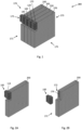
- Fig. 1 shows a schematic perspective view of a plurality of electric devices 200, 220, 240, 270 in a block of devices 280 according to an embodiment of the present disclosure.
- the plurality of devices 200, 220, 240, 270 or the block of devices 280 may be arranged in a control cabinet (not shown in Fig. 1 ).
- the electric devices 200, 220, 240, 270 may be adjacently arranged to each other in the block of devices 280.
- the electric device 200 herein also called first electric device 200, may be arranged in the middle between a second electric device 220 and a third electric device 240.
- the second electric device 220 may be adjacently arranged on a second side end 175 of the first electric device 200 and the third electric device 240 may be adjacently arranged on a first side end 174 of the first electric device 200.
- the second electric device 220 and the third electric device 240 may be arranged on opposite side ends 174, 175 of the first electric device 200.
- Each of the electric devices 200, 220, 240, 270 may include a respective bus bar module 100, 120, 140, 170.
- the bus bar modules 100, 120, 140, 170 may be arranged at a front end 171 of the respective electric device 200, 220, 240, 270 and in an upper region 172 of the respective electric device 200, 220, 240, 270. It is to be understood that further additional electric devices may be arranged adjacently to the electric devices 200, 220, 240, 270 as shown in Fig. 1 .
- Each bus bar module 100, 120, 140, 170 may include a DC-Bus (DC+/DC-) and a 24V supply voltage (24V/0V) in one bus bar module 100, 120, 140, 170 as will be described further below.
- Figs. 2A shows a schematic perspective view of the first electric device 200 with a bus bar module 100 in an assembled state.
- the bus bar module 100 is connected to the electric device 200 in the assembled state by means of contact elements, as will be described below, encapsulated in an insulating element 114.
- the bus bar module 100 may be configured to be plugged in the electric device 200.
- the bus bar module 100 is plugged in the electric device 200 in the assembled state.
- Fig. 2B shows a schematic exploded view of the electric device 100 of Fig. 2A in an unassembled state.
- the bus bar module 100 is disconnected to the electric device 200 in the unassembled state.
- the bus bar module 100 is unplugged in the electric device 200 in the assembled state.
- the electric device 200 may include receiving elements 176 on the front end 171 and in the upper region 172 of the electric device 200.
- the receiving elements 176 may be configured to receive the bus bar module 100.
- Figs. 3A to 3C show schematic perspective views of a bus bar module 100 according to an embodiment of the present disclosure.
- the bus bar module may be a two-part bus bar module 100, wherein a first portion 100a of the bus bar module 100 is arranged on top of a second portion 100b of the bus bar module 100.
- the first portion 100a and the second portion 100b of the bus bar module 100 may be constructed identically.
- the first portion 100a and the second portion 100b of the bus bar module 100 may also show differences, for example regarding a dimensioning of contact elements (see Fig. 4 ) inside the insulating element 114.
- Fig. 4 shows a schematic perspective view of three connected bus bar modules 100 of Fig. 3C .
- Each bus bar module 100 includes two contact elements 105 and an insulating element 114.
- the insulation elements 114 are shown transparently in Fig 4 in order to recognize an arrangement of the two contact elements 105 inside the insulating element 114.
- Each of the two contact elements 105 includes a first terminal 106, a second terminal 107, and a third terminal 108.
- the first terminal 106, the second terminal 107 and the third terminal 108 are electroconductive connected to each other.
- the first terminal 106 and the second terminal 107 are configured for connecting the bus bar module 100 to a another bus bar module 120, 140.
- the third terminal 108 is configured for connecting the bus bar module 100 to the electric device 200 (see Fig. 1 ).
- first terminal 106 is configured to receive a second terminal 147 of a contact element 145 of a third bus bar module 140
- the second terminal 107 is configured to be insertable into a first terminal 126 of a contact element 125 of a second bus bar module 120.
- the bus bar module 100 may be designed as a plug-in solution with contact elements 105, also called connectors.
- the bus bar module 100 as described herein may include at least one contact element 105 for transmitting DC voltage, also called a DC bus, and at least one contact element 105 for a 24V supply from one electric device 100 to another electric device 120.
- the bus bar module 100 may include a DC-Bus wherein one of the two contact elements 105 may be configured to transmit DC+ voltage power and the other contact element 105 may be configured to transmit DC- voltage power from the third bus bar module 140 over the first bus bar module 100 to the second bus bar module 120, or vice versa.
- the two contact elements 105 for DC voltage and the two contact elements 105 for 24V supply may be combined in one mechanical unit (see Fig. 3A ).
- the mechanical unit may be designed as an insulating element 114 as described herein.
- each cavity 115 is located at a first end 101 of the insulating element 114.
- the respective second portion 117 of each cavity 115 is located at a second end 102 of the insulation element 114.
- the respective third portion 118 of each cavity 115 is located at a third end 103 of the insulating element 114.
- the first end 101 and the second end 102 are oppositely arranged.
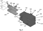
- the first terminal 106, the second terminal 107 and the third terminal 108 of the contact element 105 are arranged substantially in a plane 119.
- Fig. 5 shows two parallel arranged contact elements 105, wherein each of the two contact elements 105 may be arranged substantially in a respective plane 119. Accordingly, the first portion 116, the second portion 117 and the third portion 118 may also be arranged in the plane 119 of the respective contact element 105.
- the planes 119 are arranged parallel and at a distance to each other.
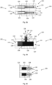
- Fig. 6A shows a schematic side view of the bus bar module 100 of Fig. 3C .
- the two contact elements 105 are arranged inside the two cavities 115 of the insulating element 114.
- Each of the two cavities 115 of the insulating element 114 may extend from a first end 101 of the insulating element 114 to the second end 102 of the insulating element 114.
- the first terminal 106 of the contact element 105 is located in a first portion 116 of the respective cavity 115.
- the second terminal 107 of the contact element 105 is located in a second portion 117 of the respective cavity 115.
- the bus bar module 100, 120, 140, 170 of a respective electric device 200, 220, 240, 270 is configured to be rotatably connected to the electric device 200, 220, 240, 270 by means of a stud 104.
- the bus bar module 100, 120, 140, 170 is rotatably connected to the respective electric device 200, 220, 240, 270 using a mounting plate 180 located at the respective electric device 200, 220, 240, 270.
- the first bus bar module 100 is configured to be rotatable about the rotation axis A such that the respective first terminals 106 (see Fig. 6B ) of the contact elements 105 (see Fig. 6B ) are disconnected to an adjacently arranged third electric device (240), and the respective third terminals 108 (see. Fig. 6B ) of the contact elements 105 (see Fig. 6B ) are disconnected to the electric device 200 if the bus bar module 100 is rotated by substantially 90-degrees around the rotation axis A (see also Fig. 13B ).
- Fig. 8 shows a schematic side view of a bus bar module 100 according to the embodiment of Fig. 7 .
- the insulating element 114 of the bus bar element 100 includes four cavities 115.
- the bus bar module 100 includes four contact elements (see Fig. 4 ) with first contact pins 109 at the first terminals of the contact element, wherein the first contact pins 109 are located inside a respective cavity 115 at a first portion 116 of the cavity 115.
- the contact element also includes contact surfaces 110 at the second terminal of the contact element, wherein the contact surfaces 110 are located inside the respective cavity 115 at the second portion 117 of the cavity 115.
- Two of the four contact elements are configured to distribute high voltage power, in particular DC voltage power with at least 300V, preferably up to 1000V, and the other two of the four contact elements are configured to distribute low voltage power, in particular 24V, preferably up to 120V.
- the rotation axis A is arranged in an area 179 of the second terminals, in particular in an area 179 of the contact surfaces 110 of the contact element such that the rotation axis A intersects the contact surfaces 110 perpendicular.
- the rotation axis A is arranged perpendicular to the second terminals or the second surfaces 110.
- the rotation axis A is designed by means of at least one stud 104.
- the at least one stud 104 extrudes from the insulating element 114 in a direction perpendicular to the contact surfaces 110 of the contact element.
- the bus bar module 100 may include two studs 104.
- a first stud 104 may extrude from a top surface 177 of the insulating element 114.
- a second stud 104 may extrude from a bottom surface 178 of the insulating element.
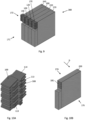
- Fig. 9 shows a schematic perspective view of electric devices 200, 220, 240, 270 in a block of devices 280 according to a further embodiment of the present disclosure.
- the plurality of devices 200, 220, 240, 270 or the block of devices 280 may be arranged in a control cabinet (not shown in Fig. 9 ).
- Each of the electric devices 200, 220, 240, 270 may include a respective bus bar module 100, 120, 140, 170.
- the bus bar modules 100, 120, 140, 170 may be arranged at a front end 171 of the respective electric device 200, 220, 240, 270 and in an upper region 172 of the respective electric device 200, 220, 240, 270.
- the electric devices 200, 220, 240, 270 may be adjacently arranged to each other in the block of devices 280.
- the electric device 200 herein also called first electric device 200
- the electric device 200 may be arranged in the middle between a second electric device 220 and a third electric device 240. Therefore, the second electric device 220 may be adjacently arranged on one side of the first electric device 200 and the third electric device 240 may be adjacently arranged on another side of the first electric device 200, wherein the second electric device 220 and the third electric device 240 may be arranged on opposite sides of the first electric device 200.
- the bus bar module 100 is shiftably connected to the respective electric device 200 using at least one corresponding sliding rail 181 located at the respective electric device 200.
- the corresponding sliding rail 181 may be configured to receive the sliding rail 113 of the bus bar module 100 if the bus bar module 100 is installed or plugged to the respective device 200 ( Fig. 10B ).
- Fig. 11 shows a schematic perspective view of a bus bar module 100 including a socket 182.
- the bus bar module may be configured to receive the socket 182.
- the socket 182 may be designed as a 24V feed-in module.
- the socket 182 may be plugged directly into the bus bar module 100 so that no extra connector has to be provided on the electric device 200.
- the socket may include two ports 183, 184 for connecting a respective wire for a 24V and a 0V connection.
- the socket 182 may additionally fixed to the insulating element 114 using a fixation plate 185.
- the fixation plate 185 may stabilize the plugged-in socket 182 to the insulating element 114.
- Fig. 12A shows a schematic perspective view of electric devices 200, 220, 240 in a block of devices 280 according to the embodiment of Fig. 1 .
- the plurality of devices 200, 220, 240 or the block of devices 280 may be arranged in a control cabinet (not shown in Fig. 12A ).
- Each of the electric devices 200, 220, 240 may include a respective bus bar module 100, 120, 140.
- the bus bar modules 100, 120, 140 may be arranged at a front end 171 of the respective electric device 200, 220, 240 and in an upper region 172 of the respective electric device 200, 220, 240.
- the electric devices 200, 220, 240 may be adjacently arranged to each other in the block of devices 280.
- the electric device 200 herein also called first electric device 200
- the electric device 200 may be arranged in the middle between a second electric device 220 and a third electric device 240. Therefore, the second electric device 220 may be adjacently arranged on one side of the first electric device 200 and the third electric device 240 may be adjacently arranged on another side of the first electric device 200, wherein the second electric device 220 and the third electric device 240 may be arranged on opposite sides of the first electric device 200. If the first electric device 200 is to be replaced in the block of devices 280 of Fig. 12A , the following steps shown in Figs. 12B to 12G may have to be carried out.
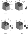
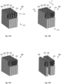
- Figs. 12B to 12G show schematic views of results of process steps of a method 300 for replacing an electric device 200 in the block of devices 280 in a perspective view.
- the first bus bar module 100 of the first electric device 200 may have to be unplugged from the first electric device 200. Therefore, the first electric device 200 may be disconnected to the adjacently arranged second electric device 220 and the third electric device 240.
- the second bus bar module 120 of the second electric device 220 may have to be unplugged from the second electric device 220. This step may provide that there is enough space to remove the first electric device 200 in an axial direction C out of the block of devices 280.
- the axial direction C may be directed from a back end 173 of the first electric device 200 to the front end 171 of the first electric device 200.
- Fig. 12D shows a result of removing the first electric device 200 from the block of devices 280.
- a fourth electric device 260 may be inserted into the block of devices 280, see Fig. 12E .
- the fourth electric device 260 may be different from the first electric device 200.
- the fourth electric device 260 may be inserted at a same position as the first electric device 200 into the block of devices 280. Therefore, the fourth electric device 260 may be arranged in the middle between the second electric device 220 and the third electric device 240.
- Figs. 12F and 12G show schematic views of results of connecting the fourth electric device 260 to the second electric device 220 and the third electric device 240, the fourth electric device 260 having replaced the first electric device 200 in the block of devices 280.
- the second bus bar module 120 may be plugged in the second electric device 220, see Fig. 12F .
- the first bus bar module 100 may be plugged in the fourth electric device 260 to connect the fourth electric device 260 to the second electric device 220 and the third electric device 240 by means of the first bus bar module 100. It is to be understood that also a new bus bar module can be used instead of the first bus bar module 100 of the first electric device 200 to connect the fourth electric device 260 to the second electric device 220 and the third electric device 240. The same applies for each bus bar module.
- the first electric device 200 has been replaced by the fourth electric device 260 in the block of devices 280.
- the first bus bar module 100 connects the fourth electric device 260 to the second electric device 220 and the third electric device 240 in the block of devices 280, see Fig. 12G .
- Fig. 13A shows a schematic perspective view of electric devices 200, 220, 240 in a block of devices 280 according to the embodiment of Fig. 7 .
- the plurality of devices 200, 220, 240 or the block of devices 280 may be arranged in a control cabinet (not shown in Fig. 13A ).
- Each of the electric devices 200, 220, 240 may include a respective bus bar module 100, 120, 140.
- the bus bar modules 100, 120, 140 may be arranged at a front end 171 of the respective electric device 200, 220, 240 and in an upper region 172 of the respective electric device 200, 220, 240.
- the electric devices 200, 220, 240 may be adjacently arranged to each other in the block of devices 280.
- the electric device 200 herein also called first electric device 200
- the electric device 200 may be arranged in the middle between a second electric device 220 and a third electric device 240. Therefore, the second electric device 220 may be adjacently arranged on one side of the first electric device 200 and the third electric device 240 may be adjacently arranged on another side of the first electric device 200, wherein the second electric device 220 and the third electric device 240 may be arranged on opposite sides of the first electric device 200. If the first electric device 200 is to be replaced in the block of devices 280 of Fig. 13A , the following steps shown in Figs. 13B to 13G may have to be carried out.
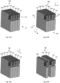
- Figs. 13B to 13G show schematic views of results of process steps of a method 400 for replacing an electric device 200 in the block of devices 280 in a perspective view.
- a second bus bar module 120 of the second electric device 220 may have to be rotated, in particular counterclockwise about a rotation axis A (see Fig. 8 ) by an angle of substantially 90-degrees. Therefore, the second electric device 220 may be disconnected to the adjacently arranged first electric device 200.
- first terminals of respective contact elements of the second bus bar module 120 may be disconnected to second terminals of respective contact elements of the first bus bar module 100 of the first electric device 200.
- this step may provide that there is enough space to remove the first electric device 200 in an axial direction C out of the block of devices 280.
- the axial direction C may be directed from a back end 173 of the first electric device 200 to the front end 171 of the first electric device 200.
- the first bus bar module 100 of the first electric device 200 may have to be rotated, in particular counterclockwise about a rotation axis A (see Fig. 8 ) by an angle of substantially 90-degrees. Therefore, the first electric device 200 may be disconnected to the adjacently arranged third electric device 240. In particular, first terminals of respective contact elements of the first bus bar module 100 may be disconnected to second terminals of respective contact elements of the third bus bar module 140 of the third electric device 240.
- Fig. 13D shows a schematic view of a result of removing the first electric device 200 from the block of devices 280.
- a fourth electric device 260 including a fourth bus bar module 160 may be inserted into the block of devices 280, see Fig. 13E .
- the fourth electric device 260 may be different from the first electric device 200.
- the fourth electric device 260 may be inserted at a same position as the first electric device 200 into the block of devices 280. Therefore, the fourth electric device 260 may be arranged in the middle between the second electric device 220 and the third electric device 240.
- Figs. 13F and 13G show schematic views of results of connecting the fourth electric device 260 to the second electric device 220 and the third electric device 240, the fourth electric device 260 having replaced the first electric device 200 in the block of devices 280.
- the fourth bus bar module 160 may have to be rotated, in particular clockwise about the rotation axis A (see Fig. 8 ) by an angle of substantially 90-degrees. Therefore, the fourth electric device 260 may be connected to the adjacently arranged third electric device 240.
- the first terminals of the respective contact elements of the fourth bus bar module 160 may be connected to the second terminals of the respective contact elements of the third bus bar module 140 of the third electric device 240, see Fig. 13F .
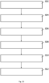
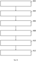
- Fig. 15 shows a flow diagram illustrating a method 300 for replacing an electric device 200 in a block of devices 280 according to an embodiment.
- a first bus bar module 100 may be unplugged from a first electric device 200 such that the first electric device 200 is disconnected to a second electric device 220 and a third electric device 240, wherein the first electric device 200 is arranged in the middle between the second electric device 220 and the third electric device 240.
- the first electric device 200 may be removed from the block of devices 280.
- a fourth electric device 260 including a fourth bus bar module 160 may be inserted into the block of devices 280.
- the fourth bus bar module 160 of the fourth electric device 260 may be rotated such that the fourth electric device 260 may be connected to the third electric device 240.
- the second bus bar module 120 of the second electric device 220 may be rotated such that the second electric device 220 may be connected to the fourth electric device 260.
Landscapes
- Engineering & Computer Science (AREA)
- Power Engineering (AREA)
- Manufacturing & Machinery (AREA)
- Multi-Conductor Connections (AREA)
Priority Applications (3)
| Application Number | Priority Date | Filing Date | Title |
|---|---|---|---|
| EP23307269.3A EP4576440A1 (de) | 2023-12-19 | 2023-12-19 | Sammelschienenmodul |
| US18/981,815 US20250202176A1 (en) | 2023-12-19 | 2024-12-16 | Bus bar module |
| CN202411867541.4A CN120184637A (zh) | 2023-12-19 | 2024-12-18 | 母线模块 |
Applications Claiming Priority (1)
| Application Number | Priority Date | Filing Date | Title |
|---|---|---|---|
| EP23307269.3A EP4576440A1 (de) | 2023-12-19 | 2023-12-19 | Sammelschienenmodul |
Publications (1)
| Publication Number | Publication Date |
|---|---|
| EP4576440A1 true EP4576440A1 (de) | 2025-06-25 |
Family
ID=89573859
Family Applications (1)
| Application Number | Title | Priority Date | Filing Date |
|---|---|---|---|
| EP23307269.3A Pending EP4576440A1 (de) | 2023-12-19 | 2023-12-19 | Sammelschienenmodul |
Country Status (3)
| Country | Link |
|---|---|
| US (1) | US20250202176A1 (de) |
| EP (1) | EP4576440A1 (de) |
| CN (1) | CN120184637A (de) |
Citations (4)
| Publication number | Priority date | Publication date | Assignee | Title |
|---|---|---|---|---|
| DE202006006659U1 (de) * | 2006-04-21 | 2006-07-06 | Phoenix Contact Gmbh & Co. Kg | Elektrisches oder elektronisches Gerät |
| WO2011141314A1 (de) * | 2010-05-10 | 2011-11-17 | Weidmüller Interface GmbH & Co. KG | Tragschienenbussystem |
| US20190089107A1 (en) * | 2016-03-11 | 2019-03-21 | Phoenix Contact Gmbh & Co. Kg | Electrical contact element for a bus element of a mounting rail bus system |
| US20230396002A1 (en) * | 2022-06-07 | 2023-12-07 | Dinkle Enterprise Co., Ltd. | Terminal block bus structure and bus module thereof |
-
2023
- 2023-12-19 EP EP23307269.3A patent/EP4576440A1/de active Pending
-
2024
- 2024-12-16 US US18/981,815 patent/US20250202176A1/en active Pending
- 2024-12-18 CN CN202411867541.4A patent/CN120184637A/zh active Pending
Patent Citations (4)
| Publication number | Priority date | Publication date | Assignee | Title |
|---|---|---|---|---|
| DE202006006659U1 (de) * | 2006-04-21 | 2006-07-06 | Phoenix Contact Gmbh & Co. Kg | Elektrisches oder elektronisches Gerät |
| WO2011141314A1 (de) * | 2010-05-10 | 2011-11-17 | Weidmüller Interface GmbH & Co. KG | Tragschienenbussystem |
| US20190089107A1 (en) * | 2016-03-11 | 2019-03-21 | Phoenix Contact Gmbh & Co. Kg | Electrical contact element for a bus element of a mounting rail bus system |
| US20230396002A1 (en) * | 2022-06-07 | 2023-12-07 | Dinkle Enterprise Co., Ltd. | Terminal block bus structure and bus module thereof |
Also Published As
| Publication number | Publication date |
|---|---|
| CN120184637A (zh) | 2025-06-20 |
| US20250202176A1 (en) | 2025-06-19 |
Similar Documents
| Publication | Publication Date | Title |
|---|---|---|
| US11109504B2 (en) | Power distribution unit with interior busbars | |
| US6795320B2 (en) | Method and apparatus for supplying data and power to panel-supported components | |
| US12261419B2 (en) | Plug-on neutral device and kit | |
| EP0551768A1 (de) | Installationseinrichtung für Netzanschluss | |
| CN105409064B (zh) | 总线连接装置 | |
| US6957974B2 (en) | System for providing data and power signals to networked devices | |
| US6433445B1 (en) | Active mating connector | |
| US20210021076A1 (en) | Single Pair Ethernet Connector | |
| US6106341A (en) | Electronic power distribution module | |
| US20250202176A1 (en) | Bus bar module | |
| US6482046B1 (en) | Cable coupler | |
| US20240114645A1 (en) | Modular and scalable power distribution | |
| US7377807B2 (en) | Modular power distribution apparatus using cables with guarded connectors | |
| CN101044655A (zh) | 馈电模块 | |
| GB2625837A (en) | System for connecting a modular electrical device to an electrical distribution panel, modular electrical device, and assembly comprising an electrical | |
| US12531356B2 (en) | Base element for an at least two-part overvoltage protector and corresponding overvoltage protector | |
| CN212991510U (zh) | 实现列头柜末端调相的快速插拔端子及列头柜配电回路 | |
| US20230209763A1 (en) | Modular and scalable power distribution | |
| WO2023141190A1 (en) | Modular and scalable power distribution system | |
| GB2534615A (en) | A creepage protection assembly and a panel box/cabinet comprising the assembly | |
| JP2000201405A (ja) | ア―ス中継端子付住宅用分電盤 |
Legal Events
| Date | Code | Title | Description |
|---|---|---|---|
| PUAI | Public reference made under article 153(3) epc to a published international application that has entered the european phase |
Free format text: ORIGINAL CODE: 0009012 |
|
| STAA | Information on the status of an ep patent application or granted ep patent |
Free format text: STATUS: REQUEST FOR EXAMINATION WAS MADE |
|
| 17P | Request for examination filed |
Effective date: 20240920 |
|
| AK | Designated contracting states |
Kind code of ref document: A1 Designated state(s): AL AT BE BG CH CY CZ DE DK EE ES FI FR GB GR HR HU IE IS IT LI LT LU LV MC ME MK MT NL NO PL PT RO RS SE SI SK SM TR |