EP4576441A1 - Ensemble connecteur électrique - Google Patents
Ensemble connecteur électrique Download PDFInfo
- Publication number
- EP4576441A1 EP4576441A1 EP23217586.9A EP23217586A EP4576441A1 EP 4576441 A1 EP4576441 A1 EP 4576441A1 EP 23217586 A EP23217586 A EP 23217586A EP 4576441 A1 EP4576441 A1 EP 4576441A1
- Authority
- EP
- European Patent Office
- Prior art keywords
- circuit board
- connecting element
- connector
- board connector
- heat sink
- Prior art date
- Legal status (The legal status is an assumption and is not a legal conclusion. Google has not performed a legal analysis and makes no representation as to the accuracy of the status listed.)
- Pending
Links
Images


Classifications
-
- H—ELECTRICITY
- H01—ELECTRIC ELEMENTS
- H01R—ELECTRICALLY-CONDUCTIVE CONNECTIONS; STRUCTURAL ASSOCIATIONS OF A PLURALITY OF MUTUALLY-INSULATED ELECTRICAL CONNECTING ELEMENTS; COUPLING DEVICES; CURRENT COLLECTORS
- H01R12/00—Structural associations of a plurality of mutually-insulated electrical connecting elements, specially adapted for printed circuits, e.g. printed circuit boards [PCB], flat or ribbon cables, or like generally planar structures, e.g. terminal strips, terminal blocks; Coupling devices specially adapted for printed circuits, flat or ribbon cables, or like generally planar structures; Terminals specially adapted for contact with, or insertion into, printed circuits, flat or ribbon cables, or like generally planar structures
- H01R12/50—Fixed connections
- H01R12/51—Fixed connections for rigid printed circuits or like structures
- H01R12/55—Fixed connections for rigid printed circuits or like structures characterised by the terminals
-
- H—ELECTRICITY
- H05—ELECTRIC TECHNIQUES NOT OTHERWISE PROVIDED FOR
- H05K—PRINTED CIRCUITS; CASINGS OR CONSTRUCTIONAL DETAILS OF ELECTRIC APPARATUS; MANUFACTURE OF ASSEMBLAGES OF ELECTRICAL COMPONENTS
- H05K7/00—Constructional details common to different types of electric apparatus
- H05K7/20—Modifications to facilitate cooling, ventilating, or heating
- H05K7/2089—Modifications to facilitate cooling, ventilating, or heating for power electronics, e.g. for inverters for controlling motor
- H05K7/20909—Forced ventilation, e.g. on heat dissipaters coupled to components
-
- H—ELECTRICITY
- H01—ELECTRIC ELEMENTS
- H01R—ELECTRICALLY-CONDUCTIVE CONNECTIONS; STRUCTURAL ASSOCIATIONS OF A PLURALITY OF MUTUALLY-INSULATED ELECTRICAL CONNECTING ELEMENTS; COUPLING DEVICES; CURRENT COLLECTORS
- H01R12/00—Structural associations of a plurality of mutually-insulated electrical connecting elements, specially adapted for printed circuits, e.g. printed circuit boards [PCB], flat or ribbon cables, or like generally planar structures, e.g. terminal strips, terminal blocks; Coupling devices specially adapted for printed circuits, flat or ribbon cables, or like generally planar structures; Terminals specially adapted for contact with, or insertion into, printed circuits, flat or ribbon cables, or like generally planar structures
- H01R12/70—Coupling devices
- H01R12/7088—Arrangements for power supply
-
- H—ELECTRICITY
- H01—ELECTRIC ELEMENTS
- H01R—ELECTRICALLY-CONDUCTIVE CONNECTIONS; STRUCTURAL ASSOCIATIONS OF A PLURALITY OF MUTUALLY-INSULATED ELECTRICAL CONNECTING ELEMENTS; COUPLING DEVICES; CURRENT COLLECTORS
- H01R12/00—Structural associations of a plurality of mutually-insulated electrical connecting elements, specially adapted for printed circuits, e.g. printed circuit boards [PCB], flat or ribbon cables, or like generally planar structures, e.g. terminal strips, terminal blocks; Coupling devices specially adapted for printed circuits, flat or ribbon cables, or like generally planar structures; Terminals specially adapted for contact with, or insertion into, printed circuits, flat or ribbon cables, or like generally planar structures
- H01R12/70—Coupling devices
- H01R12/71—Coupling devices for rigid printing circuits or like structures
- H01R12/75—Coupling devices for rigid printing circuits or like structures connecting to cables except for flat or ribbon cables
-
- H—ELECTRICITY
- H01—ELECTRIC ELEMENTS
- H01R—ELECTRICALLY-CONDUCTIVE CONNECTIONS; STRUCTURAL ASSOCIATIONS OF A PLURALITY OF MUTUALLY-INSULATED ELECTRICAL CONNECTING ELEMENTS; COUPLING DEVICES; CURRENT COLLECTORS
- H01R4/00—Electrically-conductive connections between two or more conductive members in direct contact, i.e. touching one another; Means for effecting or maintaining such contact; Electrically-conductive connections having two or more spaced connecting locations for conductors and using contact members penetrating insulation
- H01R4/28—Clamped connections, spring connections
- H01R4/30—Clamped connections, spring connections utilising a screw or nut clamping member
Definitions
- the present invention relates to an electrical circuit board connector with at least one electrical contact element, which is at least partially surrounded by a connector housing of the circuit board connector.
- the circuit board connector has at least one connecting element for electrically and mechanically connecting the circuit board connector to a power board.
- EP 2 893 596 B1 shows an electrical connector assembly having a first and a second engagement portion, wherein at least one first vent hole is formed in the first engagement portion to dissipate heat from the first engagement portion, and at least one second vent hole is formed in the second engagement portion to dissipate heat from the second engagement portion.
- the object of the present invention is to provide an electrical circuit board connector that provides the basis for transmitting high currents. It is also an object of the present invention to provide a circuit board assembly with a power board having a heat sink and with an electrical circuit board connector.
- the connecting element is designed as a cooling element for dissipating heat from the printed circuit board connector.
- the connecting element of the printed circuit board connector is arranged adjacent to the heat sink, so that a cooling air flow passing through the heat sink also reaches the connecting element provided as a cooling element.
- the connecting element or several connecting elements can form a cooling area that is located between the electrical connection to a power board (which can be realized, for example, via fastening eyes) and the electrical contact area (defined by one or more contact elements).
- the circuit board arrangement is preferably part of a machine tool that is supplied with electrical energy by accumulators.
- the invention incorporates the realization that accumulators—and, accordingly, accumulator-powered machine tools—are becoming increasingly more powerful. Due to the high electrical power, the current (or currents) that must be transmitted, for example, via a circuit board connector, is also becoming ever greater.
- the current-carrying capacity of such connectors is typically limited. If the current to be transmitted is too high, the connector can fail due to overheating. In typical connectors, small metal segments are pressed against a terminal lug by spring force to keep the electrical contact resistance as low as possible. If the connector is subjected to too much current, it heats up excessively. As the metal parts heat up, the spring force decreases, and the contact resistance and thus the heating increase even further. This is a self-reinforcing process that can lead to connector failure.
- the connecting element of the board connector is designed as a cooling element to dissipate heat from the board connector, heating of the connector can be reduced and thus the current carrying capacity can be increased.
- the connecting element has a preferably flat cooling surface with a width defined in the insertion direction of the connector housing and a length defined perpendicular to the insertion direction of the connector housing. It has proven advantageous if the length is at least twice the width.
- the length of the connecting element outside the connector housing is preferably at least 2 centimeters.
- the electrical contact element is designed as a plug-in lug.
- the connecting element is located at least partially outside the connector housing. This allows for a spatial separation of cooling (one or more cooling surfaces) and electrical contact (one or more electrical contact elements).
- the electrical contact element and the connecting element are formed integrally with one another, wherein the portion of the connecting element is preferably located completely outside the plug housing and/or the portion of the connecting element is located completely within a volume of the plug housing. It has proven advantageous if the contact element and/or the connecting element are made of metal. It has also proven advantageous if the electrical contact element is Connecting element is electrically and/or thermally coupled, for example by being designed as a common sheet metal part.
- a fastening eyelet is formed on the connecting element, on a side facing away from the contact element.
- the connecting element can advantageously be screwed to a power board via such an eyelet.
- the connection of the connecting element to the power board can be realized via a solder lug or the like.
- the printed circuit board connector has a plurality of connecting elements, preferably exactly three connecting elements. It has proven advantageous if the printed circuit board connector has a plurality of contact elements, preferably exactly six contact elements. It has also proven advantageous if two electrical contact elements are provided per connecting element. Particularly preferably, two electrical contact elements are formed integrally with the connecting element.
- the contact element and/or the connecting element are partially embedded in the connector housing, for example, by means of plastic injection molding. It has proven advantageous if the connector housing is made of plastic or comprises plastic.
- the heat sink of the power board has a cooling fin that extends substantially parallel to the connecting element, preferably to a cooling surface formed on the connecting element.
- the connecting element is aligned with the cooling fin of the heat sink, particularly with respect to its width. It has proven advantageous if multiple cooling fins and multiple connecting elements are provided, with each connecting element preferably being aligned with a respective cooling fin.
- the circuit board arrangement has a preferably tunnel-shaped air guide element. It has proven advantageous if the air guide element partially encloses the heat sink and/or the connecting element, preferably on three sides. By means of the connecting element, a cooling air flow can be guided specifically along the heat sink and/or the connecting element, thus improving heat dissipation.
- the connecting element is arranged downstream of the heat sink with respect to the cooling air flow.
- the connecting element extends through the air guide element. This allows a cooled area of the connecting elements to be separated from the electrical contact area of the contact elements.
- circuit board arrangement has a cable connector that is designed to complement the circuit board connector, wherein the circuit board connector and the cable connector are encapsulated from the environment when plugged together.
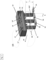
- the electrical circuit board connector 100 contains six electrical contact elements 1A, 1A', 1B, 1B', 1C, 1C'. Furthermore, the circuit board connector 100 contains a connector housing 10.
- the six contact elements 1A, 1A', 1B, 1B', 1C, 1C' are surrounded by the connector housing 10.
- the connector housing 10 protects the six contact elements 1A, 1A', 1B, 1B', 1C, 1C', among other things, from mechanical damage. According to an alternative embodiment, more or fewer than six contact elements can be provided.
- the board connector 100 further comprises three connecting elements 3A, 3B, 3C for electrically and mechanically connecting the board connector 100 to a power board 200 (cf. Figure 3 ).
- the connecting elements 3A, 3B, 3C each have a fastening eyelet 5A, 5B, 5C.
- the connecting elements 3A, 3B, 3C are located outside the connector housing 10. According to an alternative embodiment, more or fewer than three connecting elements can be included.
- the connecting elements 3A, 3B, 3C are each designed as a cooling element for dissipating heat from the board connector 100.
- Each of the connecting elements 3A, 3B, 3C - shown here as an example on the first connecting element 3A - has a flat cooling surface KOF with a width B defined in the insertion direction ER of the connector housing 10 and a length L defined perpendicular to the insertion direction ER of the connector housing 10.
- the length L is, for example, at least twice as large as the width B.
- each of the connecting elements 3A, 3B, 3C has a wall thickness S of 2 mm.
- the wall thickness S can generally be between 1.0 and 2.5 mm.
- the respective cooling surfaces KOF of the connecting elements 3A, 3B, 3C together define a cooling area KB, through which heat can be dissipated from the board connector 100.
- the connecting elements 3A, 3B, 3C are shown as straight sheet metal webs. According to alternative embodiments, each of the connecting elements 3A, 3B, 3C can also be designed in a wave-shaped or zigzag shape. Furthermore, the connecting elements 3A, 3B, 3C can also be designed irregularly in a side view.
- the relationship between the length of a Connecting element 3A, 3B, 3C to a width of a connecting element 3A, 3B, 3C can be at least 2 to 1.
- each connecting element 3A, 3B, 3C is designed in such a way that an electrical current of 40 A to 250 A can be transmitted.
- the electrical contact elements 1A, 1A', 1B, 1B', 1C, 1C' are designed as plug-in lugs, ie they have a substantially rectangular cross-section.
- Figure 2 shows a partially transparent representation of the board connector 100 of the Figure 1 .
- two electrical contact elements 1A, 1A'; 1B, 1B'; 1C, 1C' are provided for each of the three connecting elements 3A, 3B, 3C.
- the first two electrical contact elements 1A, 1A' are formed integrally with the first connecting element 3A
- the second two electrical contact elements 1B, 1B' are formed integrally with the second connecting element 3B
- the third two electrical contact elements 1C, 1C' are formed integrally with the third connecting element 3C.
- Both the electrical contact elements 1A, 1A', 1B, 1B', 1C, 1C' designed as plug-in lugs and the flat connecting elements 3A, 3B, 3C are each embedded in sections in the connector housing 10.
- FIG. 3 A preferred embodiment of a circuit board arrangement in a partially sectioned representation is shown in Figure 3
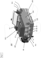
- the circuit board assembly 300 is equipped with a power board 200 having a heat sink 250 and with an electrical circuit board connector 100 which is connected to the circuit board connector 100 as already described with reference to Figure 1 and Figure 2 was described.
- the board connector 100 is screw-connected to the power board 200.
- the three connecting elements 3A, 3B, 3C of the board connector 100 are arranged next to the heat sink 250, so that a cooling air flow KLS passing through the heat sink 250 also reaches the connecting element 3A, 3B, 3C designed as a cooling element.
- the heat sink 250 has a plurality of cooling fins 255 which extend substantially parallel to the surface of the flat connecting elements 3A, 3B, 3C.
- the heat sink 250 is forced ventilated by a fan (not shown here) of a battery-operated machine tool, so that the cooling air flow KLS is generated in the direction of the arrow.
- the three connecting elements 3A, 3B, 3C - and thus the common cooling area KB (see Figure 1 ) - are related to the cooling air flow KLS downstream of the heat sink 250.
- the common cooling area KB is sandwiched between the electrical connection to the power board 200 (which is realized via the fastening eyelets already described) and the electrical contacting area (defined by the electrical contact elements 1A, 1A', 1B, 1B', 1C, 1C').
- FIG 4 shows the equipment of the circuit board arrangement 300 with a tunnel-shaped air guide element 310.
- the air guide element 310 has a tunnel-shaped shaft 315, via which the cooling air flow is directed to the heat sink 250 (cf. the sectional view of the Figure 3 ).
- the three connecting elements 3A, 3B, 3C protrude through the air guide element 310, which is only partially slotted below the connector housing 10.
- the cooling area KB is protected from external influences (such as dirt in the form of dust).
Landscapes
- Engineering & Computer Science (AREA)
- Microelectronics & Electronic Packaging (AREA)
- Physics & Mathematics (AREA)
- Thermal Sciences (AREA)
- Cooling Or The Like Of Electrical Apparatus (AREA)
Priority Applications (2)
| Application Number | Priority Date | Filing Date | Title |
|---|---|---|---|
| EP23217586.9A EP4576441A1 (fr) | 2023-12-18 | 2023-12-18 | Ensemble connecteur électrique |
| PCT/EP2024/084416 WO2025131669A1 (fr) | 2023-12-18 | 2024-12-03 | Agencement de connecteur mâle électrique |
Applications Claiming Priority (1)
| Application Number | Priority Date | Filing Date | Title |
|---|---|---|---|
| EP23217586.9A EP4576441A1 (fr) | 2023-12-18 | 2023-12-18 | Ensemble connecteur électrique |
Publications (1)
| Publication Number | Publication Date |
|---|---|
| EP4576441A1 true EP4576441A1 (fr) | 2025-06-25 |
Family
ID=89224311
Family Applications (1)
| Application Number | Title | Priority Date | Filing Date |
|---|---|---|---|
| EP23217586.9A Pending EP4576441A1 (fr) | 2023-12-18 | 2023-12-18 | Ensemble connecteur électrique |
Country Status (2)
| Country | Link |
|---|---|
| EP (1) | EP4576441A1 (fr) |
| WO (1) | WO2025131669A1 (fr) |
Citations (7)
| Publication number | Priority date | Publication date | Assignee | Title |
|---|---|---|---|---|
| EP0028187A1 (fr) * | 1979-10-26 | 1981-05-06 | Socapex | Support pour carte enfichable à raccordement électrique et thermique |
| CN101587994A (zh) * | 2008-05-20 | 2009-11-25 | 贵州航天电器股份有限公司 | 一种电源连接器的插头接触端子 |
| EP2610974B1 (fr) | 2011-12-28 | 2017-02-15 | Tyco Electronics Japan G.K. | Connecteur électrique |
| US20170373419A1 (en) * | 2016-06-24 | 2017-12-28 | Bellwether Electronic Corp | Power connector and electrical terminal assembly thereof |
| US20180006414A1 (en) * | 2016-06-30 | 2018-01-04 | Yazaki Corporation | Conductive member and electric connection box |
| EP2893596B1 (fr) | 2012-09-04 | 2019-07-31 | Tyco Electronics (Shanghai) Co., Ltd. | Connecteur électrique et ensemble connecteur électrique |
| CN113451838A (zh) * | 2021-07-14 | 2021-09-28 | 浙江吉利控股集团有限公司 | 端子结构 |
-
2023
- 2023-12-18 EP EP23217586.9A patent/EP4576441A1/fr active Pending
-
2024
- 2024-12-03 WO PCT/EP2024/084416 patent/WO2025131669A1/fr active Pending
Patent Citations (7)
| Publication number | Priority date | Publication date | Assignee | Title |
|---|---|---|---|---|
| EP0028187A1 (fr) * | 1979-10-26 | 1981-05-06 | Socapex | Support pour carte enfichable à raccordement électrique et thermique |
| CN101587994A (zh) * | 2008-05-20 | 2009-11-25 | 贵州航天电器股份有限公司 | 一种电源连接器的插头接触端子 |
| EP2610974B1 (fr) | 2011-12-28 | 2017-02-15 | Tyco Electronics Japan G.K. | Connecteur électrique |
| EP2893596B1 (fr) | 2012-09-04 | 2019-07-31 | Tyco Electronics (Shanghai) Co., Ltd. | Connecteur électrique et ensemble connecteur électrique |
| US20170373419A1 (en) * | 2016-06-24 | 2017-12-28 | Bellwether Electronic Corp | Power connector and electrical terminal assembly thereof |
| US20180006414A1 (en) * | 2016-06-30 | 2018-01-04 | Yazaki Corporation | Conductive member and electric connection box |
| CN113451838A (zh) * | 2021-07-14 | 2021-09-28 | 浙江吉利控股集团有限公司 | 端子结构 |
Also Published As
| Publication number | Publication date |
|---|---|
| WO2025131669A1 (fr) | 2025-06-26 |
Similar Documents
| Publication | Publication Date | Title |
|---|---|---|
| DE102010064592B4 (de) | Weiblicher Anschluss für ein Anschlussteil zur Verbindung mit einem mannlichen Flachstecker | |
| DE69921384T2 (de) | Leistungsverbinder | |
| EP3913716B1 (fr) | Module de batterie doté d'une pluralité d'éléments de batterie et procédé de fabrication d'un tel module | |
| EP3628533A1 (fr) | Structure de câble à refroidissement par liquide et procédé de refroidissement d'une structure de câble | |
| EP2442403A1 (fr) | Borne de connexion sans vis | |
| DE3223624C2 (de) | Kühlkörper für elektrische Bauelemente | |
| EP3114734B1 (fr) | Connecteur électrique | |
| DE102015104297A1 (de) | Fixierelement zum Anbinden einer Platine, Stromschiene und damit ausgestatteter Stromverteiler eines Fahrzeugs | |
| WO2019201390A1 (fr) | Module de connecteur enfichable blindé pour un connecteur enfichable industriel modulaire | |
| DE112014001976T5 (de) | Elektronikkomponenten-Montagestruktur und elektrische Verteilerdose | |
| DE102018213918A1 (de) | Elektrische Anschlussanordnung mit geteilter Ummantelung | |
| EP3699933A1 (fr) | Conduite d'alimentation en énergie pour véhicules | |
| DE102010051736A1 (de) | Elektrischer Durchlauferhitzer | |
| EP2095469B1 (fr) | Dispositif de montage pour recevoir des modules électroniques | |
| DE112016005773T5 (de) | Anschlusspassstück und Verbinder | |
| EP4576441A1 (fr) | Ensemble connecteur électrique | |
| DE102020133968A1 (de) | Elektrische anschlussanordnung mit vergrössertem kontaktbereich | |
| DE102010008354A1 (de) | Elektrische Anschlussklemme | |
| DE102010024155B4 (de) | Automobilsicherung zum Anschließen an einen Stromverteilungskasten sowie Kombination eines Stromverteilungskastens mit einer derartigen Automobilsicherung | |
| DE102016219238A1 (de) | Leiterplatte und Stromversorgungseinrichtung | |
| DE202009018077U1 (de) | Leistungselektronikanordnung | |
| DE10290399T5 (de) | Drahtverbindungsvorrichtung für Leiterplatte | |
| DE202015104346U1 (de) | Keramikheizer mit vergrößerter Windseitenfläche | |
| DE102021123620A1 (de) | Elektrische Steckervorrichtung, Kontakteinrichtung dafür sowie Verfahren zur Herstellung | |
| DE102021207933A1 (de) | Batteriemodul mit einer Mehrzahl an Batteriezellen und Verfahren zur Herstellung eines solchen |
Legal Events
| Date | Code | Title | Description |
|---|---|---|---|
| PUAI | Public reference made under article 153(3) epc to a published international application that has entered the european phase |
Free format text: ORIGINAL CODE: 0009012 |
|
| STAA | Information on the status of an ep patent application or granted ep patent |
Free format text: STATUS: THE APPLICATION HAS BEEN PUBLISHED |
|
| AK | Designated contracting states |
Kind code of ref document: A1 Designated state(s): AL AT BE BG CH CY CZ DE DK EE ES FI FR GB GR HR HU IE IS IT LI LT LU LV MC ME MK MT NL NO PL PT RO RS SE SI SK SM TR |