EP4576446A1 - Verdichter mit verbessertem elektrischem verbinder, insbesondere für wärmepumpe - Google Patents
Verdichter mit verbessertem elektrischem verbinder, insbesondere für wärmepumpe Download PDFInfo
- Publication number
- EP4576446A1 EP4576446A1 EP24217746.7A EP24217746A EP4576446A1 EP 4576446 A1 EP4576446 A1 EP 4576446A1 EP 24217746 A EP24217746 A EP 24217746A EP 4576446 A1 EP4576446 A1 EP 4576446A1
- Authority
- EP
- European Patent Office
- Prior art keywords
- connector body
- compressor
- electrical
- connector
- front side
- Prior art date
- Legal status (The legal status is an assumption and is not a legal conclusion. Google has not performed a legal analysis and makes no representation as to the accuracy of the status listed.)
- Pending
Links
Images


Classifications
-
- H—ELECTRICITY
- H01—ELECTRIC ELEMENTS
- H01R—ELECTRICALLY-CONDUCTIVE CONNECTIONS; STRUCTURAL ASSOCIATIONS OF A PLURALITY OF MUTUALLY-INSULATED ELECTRICAL CONNECTING ELEMENTS; COUPLING DEVICES; CURRENT COLLECTORS
- H01R13/00—Details of coupling devices of the kinds covered by groups H01R12/70 or H01R24/00 - H01R33/00
- H01R13/46—Bases; Cases
- H01R13/52—Dustproof, splashproof, drip-proof, waterproof, or flameproof cases
- H01R13/5202—Sealing means between parts of housing or between housing part and a wall, e.g. sealing rings
-
- F—MECHANICAL ENGINEERING; LIGHTING; HEATING; WEAPONS; BLASTING
- F04—POSITIVE - DISPLACEMENT MACHINES FOR LIQUIDS; PUMPS FOR LIQUIDS OR ELASTIC FLUIDS
- F04B—POSITIVE-DISPLACEMENT MACHINES FOR LIQUIDS; PUMPS
- F04B39/00—Component parts, details, or accessories, of pumps or pumping systems specially adapted for elastic fluids, not otherwise provided for in, or of interest apart from, groups F04B25/00 - F04B37/00
-
- F—MECHANICAL ENGINEERING; LIGHTING; HEATING; WEAPONS; BLASTING
- F25—REFRIGERATION OR COOLING; COMBINED HEATING AND REFRIGERATION SYSTEMS; HEAT PUMP SYSTEMS; MANUFACTURE OR STORAGE OF ICE; LIQUEFACTION SOLIDIFICATION OF GASES
- F25B—REFRIGERATION MACHINES, PLANTS OR SYSTEMS; COMBINED HEATING AND REFRIGERATION SYSTEMS; HEAT PUMP SYSTEMS
- F25B31/00—Compressor arrangements
- F25B31/02—Compressor arrangements of motor-compressor units
-
- H—ELECTRICITY
- H01—ELECTRIC ELEMENTS
- H01R—ELECTRICALLY-CONDUCTIVE CONNECTIONS; STRUCTURAL ASSOCIATIONS OF A PLURALITY OF MUTUALLY-INSULATED ELECTRICAL CONNECTING ELEMENTS; COUPLING DEVICES; CURRENT COLLECTORS
- H01R13/00—Details of coupling devices of the kinds covered by groups H01R12/70 or H01R24/00 - H01R33/00
- H01R13/40—Securing contact members in or to a base or case; Insulating of contact members
-
- H—ELECTRICITY
- H01—ELECTRIC ELEMENTS
- H01R—ELECTRICALLY-CONDUCTIVE CONNECTIONS; STRUCTURAL ASSOCIATIONS OF A PLURALITY OF MUTUALLY-INSULATED ELECTRICAL CONNECTING ELEMENTS; COUPLING DEVICES; CURRENT COLLECTORS
- H01R13/00—Details of coupling devices of the kinds covered by groups H01R12/70 or H01R24/00 - H01R33/00
- H01R13/46—Bases; Cases
- H01R13/533—Bases, cases made for use in extreme conditions, e.g. high temperature, radiation, vibration, corrosive environment, pressure
-
- H—ELECTRICITY
- H01—ELECTRIC ELEMENTS
- H01R—ELECTRICALLY-CONDUCTIVE CONNECTIONS; STRUCTURAL ASSOCIATIONS OF A PLURALITY OF MUTUALLY-INSULATED ELECTRICAL CONNECTING ELEMENTS; COUPLING DEVICES; CURRENT COLLECTORS
- H01R13/00—Details of coupling devices of the kinds covered by groups H01R12/70 or H01R24/00 - H01R33/00
- H01R13/62—Means for facilitating engagement or disengagement of coupling parts or for holding them in engagement
- H01R13/627—Snap or like fastening
-
- H—ELECTRICITY
- H01—ELECTRIC ELEMENTS
- H01R—ELECTRICALLY-CONDUCTIVE CONNECTIONS; STRUCTURAL ASSOCIATIONS OF A PLURALITY OF MUTUALLY-INSULATED ELECTRICAL CONNECTING ELEMENTS; COUPLING DEVICES; CURRENT COLLECTORS
- H01R13/00—Details of coupling devices of the kinds covered by groups H01R12/70 or H01R24/00 - H01R33/00
- H01R13/62—Means for facilitating engagement or disengagement of coupling parts or for holding them in engagement
- H01R13/629—Additional means for facilitating engagement or disengagement of coupling parts, e.g. aligning or guiding means, levers, gas pressure electrical locking indicators, manufacturing tolerances
- H01R13/631—Additional means for facilitating engagement or disengagement of coupling parts, e.g. aligning or guiding means, levers, gas pressure electrical locking indicators, manufacturing tolerances for engagement only
-
- H—ELECTRICITY
- H01—ELECTRIC ELEMENTS
- H01R—ELECTRICALLY-CONDUCTIVE CONNECTIONS; STRUCTURAL ASSOCIATIONS OF A PLURALITY OF MUTUALLY-INSULATED ELECTRICAL CONNECTING ELEMENTS; COUPLING DEVICES; CURRENT COLLECTORS
- H01R13/00—Details of coupling devices of the kinds covered by groups H01R12/70 or H01R24/00 - H01R33/00
- H01R13/66—Structural association with built-in electrical component
- H01R13/665—Structural association with built-in electrical component with built-in electronic circuit
- H01R13/6683—Structural association with built-in electrical component with built-in electronic circuit with built-in sensor
-
- H—ELECTRICITY
- H01—ELECTRIC ELEMENTS
- H01R—ELECTRICALLY-CONDUCTIVE CONNECTIONS; STRUCTURAL ASSOCIATIONS OF A PLURALITY OF MUTUALLY-INSULATED ELECTRICAL CONNECTING ELEMENTS; COUPLING DEVICES; CURRENT COLLECTORS
- H01R13/00—Details of coupling devices of the kinds covered by groups H01R12/70 or H01R24/00 - H01R33/00
- H01R13/66—Structural association with built-in electrical component
- H01R13/70—Structural association with built-in electrical component with built-in switch
- H01R13/713—Structural association with built-in electrical component with built-in switch the switch being a safety switch
- H01R13/7137—Structural association with built-in electrical component with built-in switch the switch being a safety switch with thermal interrupter
-
- H—ELECTRICITY
- H01—ELECTRIC ELEMENTS
- H01R—ELECTRICALLY-CONDUCTIVE CONNECTIONS; STRUCTURAL ASSOCIATIONS OF A PLURALITY OF MUTUALLY-INSULATED ELECTRICAL CONNECTING ELEMENTS; COUPLING DEVICES; CURRENT COLLECTORS
- H01R13/00—Details of coupling devices of the kinds covered by groups H01R12/70 or H01R24/00 - H01R33/00
- H01R13/73—Means for mounting coupling parts to apparatus or structures, e.g. to a wall
Definitions
- the invention relates to an improved electrical connector for the electrical supply of a compressor for compressing fluid, e.g., a refrigerant in a heat pump, a compressor provided with the improved electrical connector, and a heat pump.
- a compressor for compressing fluid e.g., a refrigerant in a heat pump
- a compressor provided with the improved electrical connector e.g., a heat pump
- a heat pump e.g., a heat pump
- Known electric compressors comprise a metal housing, a compression path formed in the housing between an inlet opening and an outlet opening, an electric motor arranged in the housing, a mechanical compression mechanism arranged in the housing along the compression path and operable by means of the electric motor to draw a fluid through the inlet opening, compress the drawn fluid, and push the compressed fluid out of the outlet opening.
- a compression mechanism it is known to use, for example, a so-called “rotary” mechanism with a cylindrical compartment, a suction opening, a discharge opening and a rotor positioned eccentrically with respect to the cylindrical compartment, where the compression of the refrigerant fluid occurs by means of a reduction in volume due to the eccentric rotation of the rotor.
- a so-called “twin rotary” compression mechanism comprises two rotors capable of rotating in two opposite directions, so as to reduce the noise and vibrations of the compressor.
- thermal protector device It is known to mount the thermal protector device outside the compressor housing, but the fixing thereof is complex and time-consuming. Moreover, it is necessary that the thermal protector device is installed in the correct position with respect to the compressor housing, so as to detect the maximum temperature condition of the compressor itself. The thermal protector device must in turn be connected to two electric cables which carry the signal thereof to a protection circuit.
- an electrical connector (1) for a compressor (2) comprising:
- the electrical connector can be placed with the front side against the outer surface of the compressor and fixed in place by means of the mounting seat, in a position where the first contact terminals of the electrical connector contact the first electrical terminals (for the electrical power supply of the motor) of the compressor and where the thermal protector device accommodated in the thermal protector seat faces or is in direct contact against the outer surface of the compressor, and where the first sealing edge or the first and second sealing edges ensure a hermetic closure of the electrical connection seat and the thermal protector seat.
- the clamping of the connector body against the compressor also ensures a reliable locking of the electrical contact with the first electrical terminals of the compressor.
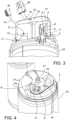
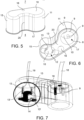
- an electrical connector 1 for a compressor 2 comprises a connector body 3 made of a synthetic material having a front side 4 intended to face and press in contact against an outer surface 5 of a compressor 2, and a rear side 7 opposite to the front side 4.
- the connector body 3 forms an electrical connection seat 8, e.g., three-phase connection, which accommodates a plurality of, e.g., three, first metal contact terminals 9 spaced apart and separated from one another (at least locally) by the synthetic material of the connector body 3.
- an electrical connection seat 8 e.g., three-phase connection, which accommodates a plurality of, e.g., three, first metal contact terminals 9 spaced apart and separated from one another (at least locally) by the synthetic material of the connector body 3.
- the first contact terminals 9 are (accessible only on the front side 4 and) intended to contact corresponding first electrical terminals 9' of the compressor 2.
- the connector body 3 further forms a thermal protector seat 12 at a distance from the electrical connection seat 8 and which accommodates at least two metal contact terminals 13 spaced apart and separated from one another (at least locally) by the synthetic material of the connector body 3.
- the connector body 3 further forms a mounting seat 16 spaced apart from (and preferably outside) the electrical connection seat 8 and spaced apart from (and preferably outside) the thermal protector seat 12, for mounting and clamping the connector body 3 to the compressor 2.
- the mounting seat 16 comprises a through hole from the front side 4 to the rear side 7 of the connector body 3, through which the connector body 3 is fittable onto a threaded pin 22 protruding from the compressor 2 in a predefined connection position, and fixable in place by a nut 23 screwed onto the threaded pin 22 against the rear side 7 of the connector body 3.
- the mounting seat 16 is preferably formed in an intermediate position or halfway between the electrical connection seat 8 and the thermal protector seat 12.
- the described positioning of the mounting seat 16 ensures a central and balanced clamping and a more even sealing pressure along the first and/or second sealing edges.
- the first sealing edge 17, and/or the second sealing edge can be formed by a gasket made of an elastomeric material other than the synthetic material of the connector body 3 and connected to the connector body 3 by co-molding or gluing or interlocking or insertion or fitting, or by simple interposition between the connector body and the compressor 2 when mounting the electrical connector 1 on the compressor 2.
- the connector body 3 and/or the first sealing edge 17 and/or the second sealing edge has (in the non-deformed configuration thereof) a shape or curvature complementary to the shape or curvature of the outer surface 5 of the compressor 2.
- the first contact terminals 9 are positioned fixed or rigidly in the connector body 3 and the first electrical terminals 9' are positioned rigidly or fixed to the compressor 2 and engageable to one another by translational insertion, so as to obtain, together with the threaded pin 22 and the mounting seat 16, a shape reference for a predetermined connection positioning which is easy to carry out.
- the second contact terminals 13 are positioned fixed or rigidly in the connector body 3 and the second electrical terminals 13' are positioned rigidly or fixed to the thermal protector device 14 and engageable to one another by translational insertion parallel to a direction of insertion of the thermal protector device 14 into the thermal protector seat 12 from the front side 4 toward the rear side 7, so as to obtain a shape reference for a quick and planned positioning of the thermal protector device 14.
- the second contact terminals 13 comprise cable lugs connected or crimped to electric wires of the second electric cable 19 and forming a female coupling seat facing the front side 4, adapted to receive with interference a corresponding rod of the second electrical terminals 13'.
- the thermal protector device 14 can comprise one of a thermal sensor, a thermal protector, thermostat, thermal switch, a so-called "Klixon", connected to an electrical safety circuit configured to perform a shutdown under abnormal temperature conditions.
- the first electric cable 18 can comprise a plurality of electric wires isolated from one another, possibly joined by a single insulation sheath and outer protection.
- the first electric cable 18 advantageously has a first quick connector 28, e.g., of the HXT VC-04P type with 62002-81 PT-1T2 terminals, or of the Zuch HP6204J-4Y type with TR6204J-1301 terminals, e.g., with four poles.
- a ground cable 29 connectable to the metal housing 24 of the compressor 2 can be connected to an electric wire of the first electric cable 18 or to a pole of the first quick connector 28.
- the second electric cable 19 can comprise a plurality of electric wires isolated from one another, possibly joined by a single insulation sheath and outer protection.
- the second electric cable 19 advantageously has a second quick connector 30, e.g., of the Minifit type with 5558TL terminals, e.g., with two poles.
- the electric compressor 2 comprises a metal housing 24, a compression path 25 formed in the housing 24 between an inlet opening and an outlet opening, an electric motor 26 arranged in the housing 24, a mechanical compression mechanism 27 arranged in the housing 24 along the compression path 25 and operable by means of the electric motor 26 to draw a fluid through the inlet opening, compress the drawn fluid, and push the compressed fluid out of the outlet opening.
- the electric motor 26 is advantageously a three-phase motor controllable by an inverter, for example.
- the housing 24 of the compressor 2 there is provided a group of, for example three, first pin-shaped electrical terminals 9' protruding from a base plate towards the outside of the compressor 2.
- a threaded pin 22 is Also connected (e.g., welded) to the housing 24 .
- a threaded pin 22 is also connected (e.g., welded) to the housing 24 .
- the compressor 2 provided with the electrical connector 1 has technical advantages similar to those described with reference to the electrical connector 1.
- the electrical connector 1 can be placed with the front side 4 against the outer surface 5 of the compressor 2 and fixed in place by means of the mounting seat 16, in a position where the first contact terminals 9 of the electrical connector 1 contact the first electrical terminals 9' (for the electrical power supply of the motor) of the compressor 2 and where the thermal protector device 14 accommodated in the thermal protector seat 12 faces or is in direct contact against the outer surface 5 of the compressor 2, and where the first sealing edge 17 or the first and second sealing edges ensure a hermetic closure of the electrical connection seat 8 and the thermal protector seat 12.
- the electrical connector allows creating the electrical connections for the motor and mounting the thermal protector device 14 with a single and quick plug & play gesture, and ensures the planned positions of the individual components.
- the clamping of the connector body 3 against the compressor 2 also ensures a reliable locking of the electrical contact with the first electrical terminals 9' of the compressor 2.
- the electrical connector 1 and the compressor 2 with the electrical connector 1 facilitate the positioning and assembly of the thermal protector device to the compressor housing, improve the accessibility (for maintenance purposes) of the connection of the thermal protector device after being first mounted to the compressor, protect the mounted thermal protector device from the external environment (impact, moisture, dust), simplify and accelerate the electrical connection of the compressor motor, protect and isolate the electrical connection region from the external environment (impact, moisture, dust, concentration of flammable or explosive gas).
Landscapes
- Engineering & Computer Science (AREA)
- Mechanical Engineering (AREA)
- General Engineering & Computer Science (AREA)
- Microelectronics & Electronic Packaging (AREA)
- Physics & Mathematics (AREA)
- Thermal Sciences (AREA)
- Compressor (AREA)
Applications Claiming Priority (1)
| Application Number | Priority Date | Filing Date | Title |
|---|---|---|---|
| IT102023000027480A IT202300027480A1 (it) | 2023-12-20 | 2023-12-20 | Compressore con connettore elettrico migliorato, in particolare per pompa di calore |
Publications (1)
| Publication Number | Publication Date |
|---|---|
| EP4576446A1 true EP4576446A1 (de) | 2025-06-25 |
Family
ID=90457890
Family Applications (1)
| Application Number | Title | Priority Date | Filing Date |
|---|---|---|---|
| EP24217746.7A Pending EP4576446A1 (de) | 2023-12-20 | 2024-12-05 | Verdichter mit verbessertem elektrischem verbinder, insbesondere für wärmepumpe |
Country Status (3)
| Country | Link |
|---|---|
| EP (1) | EP4576446A1 (de) |
| CN (1) | CN120184655A (de) |
| IT (1) | IT202300027480A1 (de) |
Citations (2)
| Publication number | Priority date | Publication date | Assignee | Title |
|---|---|---|---|---|
| EP0793068A1 (de) * | 1996-02-29 | 1997-09-03 | EMBRACO EUROPE S.r.l. | Stromversorgungs- und Schutzeinrichtung für einen hermetischen Verdichter einer Kältemaschine, Anschlussvorrichting zur Verbindung elektrischer Bauteile und hermetischer Verdichter mit einer derartigen Vorrichtung |
| US6102666A (en) * | 1998-12-28 | 2000-08-15 | U.S. Natural Resources, Inc. | Sealed electrical connector assembly |
-
2023
- 2023-12-20 IT IT102023000027480A patent/IT202300027480A1/it unknown
-
2024
- 2024-12-05 EP EP24217746.7A patent/EP4576446A1/de active Pending
- 2024-12-18 CN CN202411870006.4A patent/CN120184655A/zh active Pending
Patent Citations (2)
| Publication number | Priority date | Publication date | Assignee | Title |
|---|---|---|---|---|
| EP0793068A1 (de) * | 1996-02-29 | 1997-09-03 | EMBRACO EUROPE S.r.l. | Stromversorgungs- und Schutzeinrichtung für einen hermetischen Verdichter einer Kältemaschine, Anschlussvorrichting zur Verbindung elektrischer Bauteile und hermetischer Verdichter mit einer derartigen Vorrichtung |
| US6102666A (en) * | 1998-12-28 | 2000-08-15 | U.S. Natural Resources, Inc. | Sealed electrical connector assembly |
Also Published As
| Publication number | Publication date |
|---|---|
| CN120184655A (zh) | 2025-06-20 |
| IT202300027480A1 (it) | 2025-06-20 |
Similar Documents
| Publication | Publication Date | Title |
|---|---|---|
| US8618703B2 (en) | Motor driven compressor | |
| EP2439826B1 (de) | Kabeleinführungsdichtung für motorbetriebener Verdichter | |
| EP2836715B1 (de) | Kompressor mit versetztem elektrischen anschlusskasten mit abgewinkelten bolzen | |
| US20130330217A1 (en) | Motor-driven compressor | |
| MXPA96006393A (en) | Electric connection pin | |
| US9279425B2 (en) | Hermetic electrical feedthrough assembly for a compressor | |
| US12088039B2 (en) | Seal arrangement of a plug-in connection for establishing electrical connections and a device for driving a compressor with the seal arrangement | |
| US10738780B2 (en) | Electric compressor | |
| EP4576446A1 (de) | Verdichter mit verbessertem elektrischem verbinder, insbesondere für wärmepumpe | |
| US7175448B2 (en) | Compressor having a terminal cluster block with locking end fittings | |
| EP0967689B1 (de) | Interner Masse Anschlussstift für einen gekapselten Kompressor | |
| US9651052B2 (en) | Device for securing and electrically connecting a sealed compressor | |
| EP1867874B1 (de) | Elektromotorgetriebener verdichter | |
| US9051835B2 (en) | Offset electrical terminal box with angled studs | |
| US20140134018A1 (en) | Flammable refrigerant systems and compressors | |
| JP7743194B2 (ja) | 電動圧縮機 | |
| WO2015054289A2 (en) | Hermetic electrical feedthrough assembly for a compressor | |
| JP2782173B2 (ja) | 密閉形電動圧縮機用保護装置 | |
| KR100629594B1 (ko) | 압축기의 전원접속장치 | |
| EP4343151B1 (de) | Elektrische vorrichtung mit integriertem temperatursensor | |
| EP3430262B1 (de) | Hermetische anschlussdose und anschlussstecker zur verwendung in einem hermetisch gekappselten verdichter | |
| US20250264106A1 (en) | Electric compressor | |
| JP2014122565A (ja) | 圧縮機 | |
| KR20090012616A (ko) | 밀폐형 압축기의 보호 장치 | |
| CN119181986A (zh) | 端子组件、压缩机和暖通设备 |
Legal Events
| Date | Code | Title | Description |
|---|---|---|---|
| PUAI | Public reference made under article 153(3) epc to a published international application that has entered the european phase |
Free format text: ORIGINAL CODE: 0009012 |
|
| STAA | Information on the status of an ep patent application or granted ep patent |
Free format text: STATUS: THE APPLICATION HAS BEEN PUBLISHED |
|
| AK | Designated contracting states |
Kind code of ref document: A1 Designated state(s): AL AT BE BG CH CY CZ DE DK EE ES FI FR GB GR HR HU IE IS IT LI LT LU LV MC ME MK MT NL NO PL PT RO RS SE SI SK SM TR |
|
| STAA | Information on the status of an ep patent application or granted ep patent |
Free format text: STATUS: REQUEST FOR EXAMINATION WAS MADE |
|
| 17P | Request for examination filed |
Effective date: 20251031 |