EP4576466A2 - Schutzschaltung, steuerungsverfahren und fotovoltaisches system - Google Patents
Schutzschaltung, steuerungsverfahren und fotovoltaisches system Download PDFInfo
- Publication number
- EP4576466A2 EP4576466A2 EP24221523.4A EP24221523A EP4576466A2 EP 4576466 A2 EP4576466 A2 EP 4576466A2 EP 24221523 A EP24221523 A EP 24221523A EP 4576466 A2 EP4576466 A2 EP 4576466A2
- Authority
- EP
- European Patent Office
- Prior art keywords
- phase
- current
- fault
- inverter circuit
- signal
- Prior art date
- Legal status (The legal status is an assumption and is not a legal conclusion. Google has not performed a legal analysis and makes no representation as to the accuracy of the status listed.)
- Pending
Links
Images


Classifications
-
- H—ELECTRICITY
- H02—GENERATION; CONVERSION OR DISTRIBUTION OF ELECTRIC POWER
- H02H—EMERGENCY PROTECTIVE CIRCUIT ARRANGEMENTS
- H02H7/00—Emergency protective circuit arrangements specially adapted for specific types of electric machines or apparatus or for sectionalised protection of cable or line systems, and effecting automatic switching in the event of an undesired change from normal working conditions
- H02H7/20—Emergency protective circuit arrangements specially adapted for specific types of electric machines or apparatus or for sectionalised protection of cable or line systems, and effecting automatic switching in the event of an undesired change from normal working conditions for electronic equipment
-
- H—ELECTRICITY
- H02—GENERATION; CONVERSION OR DISTRIBUTION OF ELECTRIC POWER
- H02M—APPARATUS FOR CONVERSION BETWEEN AC AND AC, BETWEEN AC AND DC, OR BETWEEN DC AND DC, AND FOR USE WITH MAINS OR SIMILAR POWER SUPPLY SYSTEMS; CONVERSION OF DC OR AC INPUT POWER INTO SURGE OUTPUT POWER; CONTROL OR REGULATION THEREOF
- H02M1/00—Details of apparatus for conversion
- H02M1/32—Means for protecting converters other than automatic disconnection
-
- H—ELECTRICITY
- H02—GENERATION; CONVERSION OR DISTRIBUTION OF ELECTRIC POWER
- H02H—EMERGENCY PROTECTIVE CIRCUIT ARRANGEMENTS
- H02H1/00—Details of emergency protective circuit arrangements
- H02H1/0007—Details of emergency protective circuit arrangements concerning the detecting means
-
- H—ELECTRICITY
- H02—GENERATION; CONVERSION OR DISTRIBUTION OF ELECTRIC POWER
- H02H—EMERGENCY PROTECTIVE CIRCUIT ARRANGEMENTS
- H02H3/00—Emergency protective circuit arrangements for automatic disconnection directly responsive to an undesired change from normal electric working condition with or without subsequent reconnection ; integrated protection
- H02H3/08—Emergency protective circuit arrangements for automatic disconnection directly responsive to an undesired change from normal electric working condition with or without subsequent reconnection ; integrated protection responsive to excess current
- H02H3/087—Emergency protective circuit arrangements for automatic disconnection directly responsive to an undesired change from normal electric working condition with or without subsequent reconnection ; integrated protection responsive to excess current for DC applications
-
- H—ELECTRICITY
- H02—GENERATION; CONVERSION OR DISTRIBUTION OF ELECTRIC POWER
- H02H—EMERGENCY PROTECTIVE CIRCUIT ARRANGEMENTS
- H02H3/00—Emergency protective circuit arrangements for automatic disconnection directly responsive to an undesired change from normal electric working condition with or without subsequent reconnection ; integrated protection
- H02H3/08—Emergency protective circuit arrangements for automatic disconnection directly responsive to an undesired change from normal electric working condition with or without subsequent reconnection ; integrated protection responsive to excess current
- H02H3/10—Emergency protective circuit arrangements for automatic disconnection directly responsive to an undesired change from normal electric working condition with or without subsequent reconnection ; integrated protection responsive to excess current additionally responsive to some other abnormal electrical conditions
- H02H3/105—Emergency protective circuit arrangements for automatic disconnection directly responsive to an undesired change from normal electric working condition with or without subsequent reconnection ; integrated protection responsive to excess current additionally responsive to some other abnormal electrical conditions responsive to excess current and fault current to earth
-
- H—ELECTRICITY
- H02—GENERATION; CONVERSION OR DISTRIBUTION OF ELECTRIC POWER
- H02H—EMERGENCY PROTECTIVE CIRCUIT ARRANGEMENTS
- H02H3/00—Emergency protective circuit arrangements for automatic disconnection directly responsive to an undesired change from normal electric working condition with or without subsequent reconnection ; integrated protection
- H02H3/26—Emergency protective circuit arrangements for automatic disconnection directly responsive to an undesired change from normal electric working condition with or without subsequent reconnection ; integrated protection responsive to difference between voltages or between currents; responsive to phase angle between voltages or between currents
- H02H3/32—Emergency protective circuit arrangements for automatic disconnection directly responsive to an undesired change from normal electric working condition with or without subsequent reconnection ; integrated protection responsive to difference between voltages or between currents; responsive to phase angle between voltages or between currents involving comparison of the voltage or current values at corresponding points in different conductors of a single system, e.g. of currents in go and return conductors
- H02H3/34—Emergency protective circuit arrangements for automatic disconnection directly responsive to an undesired change from normal electric working condition with or without subsequent reconnection ; integrated protection responsive to difference between voltages or between currents; responsive to phase angle between voltages or between currents involving comparison of the voltage or current values at corresponding points in different conductors of a single system, e.g. of currents in go and return conductors of a three-phase system
-
- H—ELECTRICITY
- H02—GENERATION; CONVERSION OR DISTRIBUTION OF ELECTRIC POWER
- H02H—EMERGENCY PROTECTIVE CIRCUIT ARRANGEMENTS
- H02H7/00—Emergency protective circuit arrangements specially adapted for specific types of electric machines or apparatus or for sectionalised protection of cable or line systems, and effecting automatic switching in the event of an undesired change from normal working conditions
- H02H7/10—Emergency protective circuit arrangements specially adapted for specific types of electric machines or apparatus or for sectionalised protection of cable or line systems, and effecting automatic switching in the event of an undesired change from normal working conditions for converters; for rectifiers
- H02H7/12—Emergency protective circuit arrangements specially adapted for specific types of electric machines or apparatus or for sectionalised protection of cable or line systems, and effecting automatic switching in the event of an undesired change from normal working conditions for converters; for rectifiers for static converters or rectifiers
- H02H7/122—Emergency protective circuit arrangements specially adapted for specific types of electric machines or apparatus or for sectionalised protection of cable or line systems, and effecting automatic switching in the event of an undesired change from normal working conditions for converters; for rectifiers for static converters or rectifiers for inverters, i.e. DC/AC converters
- H02H7/1222—Emergency protective circuit arrangements specially adapted for specific types of electric machines or apparatus or for sectionalised protection of cable or line systems, and effecting automatic switching in the event of an undesired change from normal working conditions for converters; for rectifiers for static converters or rectifiers for inverters, i.e. DC/AC converters responsive to abnormalities in the input circuit, e.g. transients in the DC input
-
- H—ELECTRICITY
- H02—GENERATION; CONVERSION OR DISTRIBUTION OF ELECTRIC POWER
- H02M—APPARATUS FOR CONVERSION BETWEEN AC AND AC, BETWEEN AC AND DC, OR BETWEEN DC AND DC, AND FOR USE WITH MAINS OR SIMILAR POWER SUPPLY SYSTEMS; CONVERSION OF DC OR AC INPUT POWER INTO SURGE OUTPUT POWER; CONTROL OR REGULATION THEREOF
- H02M7/00—Conversion of AC power input into DC power output; Conversion of DC power input into AC power output
- H02M7/42—Conversion of DC power input into AC power output without possibility of reversal
- H02M7/44—Conversion of DC power input into AC power output without possibility of reversal by static converters
- H02M7/48—Conversion of DC power input into AC power output without possibility of reversal by static converters using discharge tubes with control electrode or semiconductor devices with control electrode
- H02M7/53—Conversion of DC power input into AC power output without possibility of reversal by static converters using discharge tubes with control electrode or semiconductor devices with control electrode using devices of a triode or transistor type requiring continuous application of a control signal
- H02M7/537—Conversion of DC power input into AC power output without possibility of reversal by static converters using discharge tubes with control electrode or semiconductor devices with control electrode using devices of a triode or transistor type requiring continuous application of a control signal using semiconductor devices only, e.g. single switched pulse inverters
- H02M7/5387—Conversion of DC power input into AC power output without possibility of reversal by static converters using discharge tubes with control electrode or semiconductor devices with control electrode using devices of a triode or transistor type requiring continuous application of a control signal using semiconductor devices only, e.g. single switched pulse inverters in a bridge configuration
-
- H—ELECTRICITY
- H02—GENERATION; CONVERSION OR DISTRIBUTION OF ELECTRIC POWER
- H02H—EMERGENCY PROTECTIVE CIRCUIT ARRANGEMENTS
- H02H3/00—Emergency protective circuit arrangements for automatic disconnection directly responsive to an undesired change from normal electric working condition with or without subsequent reconnection ; integrated protection
- H02H3/02—Details
- H02H3/021—Details concerning the disconnection itself, e.g. at a particular instant, particularly at zero value of current, disconnection in a predetermined order
- H02H3/023—Details concerning the disconnection itself, e.g. at a particular instant, particularly at zero value of current, disconnection in a predetermined order by short-circuiting
-
- H—ELECTRICITY
- H02—GENERATION; CONVERSION OR DISTRIBUTION OF ELECTRIC POWER
- H02H—EMERGENCY PROTECTIVE CIRCUIT ARRANGEMENTS
- H02H3/00—Emergency protective circuit arrangements for automatic disconnection directly responsive to an undesired change from normal electric working condition with or without subsequent reconnection ; integrated protection
- H02H3/02—Details
- H02H3/033—Details with several disconnections in a preferential order, e.g. following priority of the users, load repartition
-
- H—ELECTRICITY
- H02—GENERATION; CONVERSION OR DISTRIBUTION OF ELECTRIC POWER
- H02H—EMERGENCY PROTECTIVE CIRCUIT ARRANGEMENTS
- H02H3/00—Emergency protective circuit arrangements for automatic disconnection directly responsive to an undesired change from normal electric working condition with or without subsequent reconnection ; integrated protection
- H02H3/24—Emergency protective circuit arrangements for automatic disconnection directly responsive to an undesired change from normal electric working condition with or without subsequent reconnection ; integrated protection responsive to undervoltage or no-voltage
- H02H3/243—Emergency protective circuit arrangements for automatic disconnection directly responsive to an undesired change from normal electric working condition with or without subsequent reconnection ; integrated protection responsive to undervoltage or no-voltage for DC systems
-
- H—ELECTRICITY
- H03—ELECTRONIC CIRCUITRY
- H03K—PULSE TECHNIQUE
- H03K19/00—Logic circuits, i.e. having at least two inputs acting on one output; Inverting circuits
- H03K19/20—Logic circuits, i.e. having at least two inputs acting on one output; Inverting circuits characterised by logic function, e.g. AND, OR, NOR, NOT circuits
Definitions
- the present disclosure is intended to solve at least one of the technical problems existing in the prior art.
- the present disclosure provides a protection circuit, a control method and a photovoltaic system.
- the present disclosure not only can disconnect the relay safely, but also can cut off the loop of the short-circuit current, thereby preventing damage of the short-circuit current on components in the circuit.
- the present disclosure provides a protection circuit, where the protection circuit is applied to a three-phase inverter circuit; a DC side of the three-phase inverter circuit is configured to connect a power supply assembly; an output terminal of each phase in the three-phase inverter circuit is provided with a relay assembly; and the protection circuit includes: a controllable power device in parallel connection with a bridge arm in the three-phase inverter circuit;
- the controller in response to an STG fault between the three-phase inverter circuit and the power supply assembly, controls the controllable power device to be on, such that a short-circuit current flowing through a flyback diode in the lower bridge arm is shunted by the controllable power device, thereby preventing damage of the overlarge short-circuit current on the flyback diode in the bridge arm.
- the relay assembly of each phase is disconnected by the controller. This not only can disconnect the relay assembly safely, but also can cut off the loop of the short-circuit current, thereby preventing damage of the short-circuit current on components in the circuit.
- the bridge arm includes an upper bridge arm and a lower bridge arm; and the fault detection module is configured to generate a first fault signal when detecting an anode STG fault of the power supply assembly, and/or generate a second fault signal when detecting a cathode STG fault of the power supply assembly; and the controller is configured to control the controllable power device in parallel connection with the upper bridge arm to be on when receiving the first fault signal, and/or control the controllable power device in parallel connection with the lower bridge arm to be on when receiving the second fault signal.
- the fault detection module includes:
- the signal conversion module includes:
- the signal conversion module further includes: a data filtering unit, the data filtering unit including an input terminal electrically connected to an output terminal of the overcurrent detection module, an output terminal of the common-mode current detection module and an output terminal of the voltage detection module, and configured to filter the first overcurrent signal, the second overcurrent signal, the first common-mode current signal, the second common-mode current signal, the first voltage-to-ground signal and/or the second voltage-to-ground signal.
- a data filtering unit including an input terminal electrically connected to an output terminal of the overcurrent detection module, an output terminal of the common-mode current detection module and an output terminal of the voltage detection module, and configured to filter the first overcurrent signal, the second overcurrent signal, the first common-mode current signal, the second common-mode current signal, the first voltage-to-ground signal and/or the second voltage-to-ground signal.
- the relay assembly includes a plurality of relays connected in series; and the controller is electrically connected to the relays, and configured to use at least two relay disconnecting sequences when disconnecting the relay assembly repeatedly.
- the relay assembly includes a first relay and a second relay connected in series; and the controller is configured to execute the following operations alternately:
- controllable power device includes silicon controlled rectifiers (SCRs) corresponding to output phases of the three-phase inverter circuit;
- the controllable power device is a fully-controlled power device; an output node of the three-phase inverter circuit is further connected to a filter inductor; and a terminal of the filter inductor away from the output node is electrically connected to an output terminal of the fully-controlled power device.
- the controller includes:
- the three-phase inverter circuit uses a three-phase four-wire system; and the main breaking module is further configured to enter the main breaking stage after the preliminary breaking stage, and disconnect, when each phase meets at least one of the following conditions, the relay assembly of the corresponding phase:
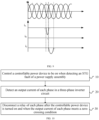
- the present disclosure provides a control method, where the control method is applied to a three-phase inverter circuit; a DC side of the three-phase inverter circuit is configured to connect a power supply assembly; an output terminal of each phase in the three-phase inverter circuit is provided with a relay assembly; a bridge arm in the three-phase inverter circuit is in parallel connection with a controllable power device; and the control method includes: controlling the controllable power device to be on when detecting an STG fault of the power supply assembly;
- the controller in response to an STG fault between the three-phase inverter circuit and the power supply assembly, controls the controllable power device to be on, such that a short-circuit current flowing through a flyback diode in the lower bridge arm is shunted by the controllable power device, thereby preventing damage of the overlarge short-circuit current on the flyback diode in the bridge arm.
- the relay assembly of each phase is disconnected by the controller. This not only can disconnect the relay assembly safely, but also can cut off the loop of the short-circuit current, thereby preventing damage of the short-circuit current on components in the circuit.
- the disconnecting the relay assembly of each phase when the output current of each phase meets a zero-crossing condition includes:
- the bridge arm of the three-phase inverter circuit includes an upper bridge arm; and the controlling the controllable power device to be on when detecting an STG fault includes:
- the bridge arm of the three-phase inverter circuit includes a lower bridge arm; and the controlling the controllable power device to be on when detecting an STG fault includes:
- the relay assembly includes a plurality of relays connected in series; and the control method further includes: using at least two relay disconnecting sequences when disconnecting the relay assembly repeatedly.
- the present disclosure provides a photovoltaic system, including a power supply assembly and an inverter, where the inverter includes a DC side configured to connect the power supply assembly, and an AC side configured to connect a power grid; and the inverter includes the foregoing protection circuit, or a controller for realizing the foregoing control method.
- the controller in response to an STG fault between the three-phase inverter circuit and the power supply assembly, controls the controllable power device to be on, such that a short-circuit current flowing through a flyback diode in the lower bridge arm is shunted by the controllable power device, thereby preventing damage of the overlarge short-circuit current on the flyback diode in the bridge arm.
- the relay assembly of each phase is disconnected by the controller. This not only can disconnect the relay assembly safely, but also can cut off the loop of the short-circuit current, thereby preventing damage of the short-circuit current on components in the circuit.
- 100 power supply assembly
- 200 voltage booster circuit
- 300 three-phase inverter circuit
- 410 overcurrent detection module
- 420 common-mode current detection module
- 430 voltage detection module
- 441 signal latch circuit
- 442 data filtering unit
- 500 current detection circuit
- K relay assembly
- K1 first relay
- K2 second relay
- U1-U4 first to fourth AND gates
- U5 OR gate
- Q controllable power device
- L filter inductor.
- circuit means an electrically conductive loop consisting of at least one element or subcircuit connected electrically or electromagnetically.
- an element or circuit When an element or circuit is referred to as being “coupled” or “connected” to another element or an element/circuit is “coupled” or “connected” between two nodes, it can be directly coupled or connected to another element, or there may be an intermediate element.
- the connection between elements may be a physical connection, a logical connection, or a combination thereof.
- an element is referred to as being “directly coupled to” or “directly connected to” another element, it means that there is no intermediate element between the two.
- first and second are used to distinguish similar objects and are not intended to describe a specific order or sequence. It should be understood that numerals used in such a way may be interchanged under appropriate circumstances so that the embodiments of the present disclosure can be implemented in an order other than those illustrated or described herein, the objects distinguished by "first”, “second”, and the like are usually of one type, and the number of objects is not limited. For example, one or more first objects may be provided.
- “and/or” in the specification and claims indicates at least one of the connected objects, and the character “/" generally indicates an "or” relationship between associated objects.
- the photovoltaic system usually includes a photovoltaic assembly and an inverter.
- the photovoltaic assembly is a large-area solar panel formed by connecting solar panels in series and encapsulating the solar panels, and can be configured to convert solar energy into a DC.
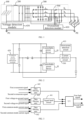
- the inverter includes voltage booster circuit 200 and three-phase inverter circuit 300.
- the voltage booster circuit 200 may be configured to convert an output voltage of the photovoltaic assembly into a higher and more stable voltage.
- the three-phase inverter circuit 300 is configured to convert the DC of the photovoltaic assembly into an AC, which can be directly merged into a power grid or directly supplied to electrical appliances.
- an embodiment of the present disclosure provides a protection circuit.
- the protection circuit is applied to three-phase inverter circuit 300.
- a DC side of the three-phase inverter circuit 300 is configured to connect power supply assembly 100.
- An output terminal of each phase in the three-phase inverter circuit 300 is provided with relay assembly K.
- the protection circuit includes: controllable power device Q, a fault detection module, current detection circuit 500, and a controller.
- the controllable power device Q is in parallel connection with a bridge arm in the three-phase inverter circuit 300.
- the fault detection module is electrically connected to the three-phase inverter circuit 300, and configured to generate a fault signal when detecting an STG fault.
- the current detection circuit 500 is electrically connected to the three-phase inverter circuit 300, and configured to detect an output current of each phase in the three-phase inverter circuit 300.
- the controller is electrically connected to the fault detection module, the current detection circuit 500 and the relay assembly K, and configured to control the controllable power device Q to be on after receiving the fault signal, and disconnect the relay assembly K of each phase when the output current of each phase meets a zero-crossing condition.
- the power supply assembly 100 may be a photovoltaic assembly.
- the photovoltaic assembly is configured to transmit electric energy to the three-phase inverter circuit 300 through a photovoltaic cable.
- the STG fault may occur on a cable connected to an anode of the photovoltaic assembly, and may also occur on a cable connected to the anode of the photovoltaic assembly.
- the bridge arm in the three-phase inverter circuit 300 includes an upper bridge arm and a lower bridge arm.
- the upper bridge arm and the lower bridge arm each include at least one switching tube.
- the switching tube may be a metal-oxide-semiconductor field-effect transistor (MOSFET) or an insulated gate bipolar transistor (IGBT).
- a flyback diode is provided in the switching tube.
- the controllable power device Q is in parallel connection with the bridge arm in the three-phase inverter circuit 300. When the circuit works normally, the controllable power device Q is in an off state, without affecting normal operation of the three-phase inverter circuit 300 and generating excessive heat. When the STG fault is detected, the controllable power device Q is turned on to shunt a short-circuit current flowing through the flyback diode in the bridge arm, thereby preventing damage of the short-circuit current on other devices in the circuit.
- the controllable power device Q may be a fully-controlled power device, and may also be a half-controlled power device.
- the specific type of the controllable power device Q may be selected according to an actual application scenario, and is not limited herein.
- the controllable power device Q may be a thyristor, an MOSFET or an IGBT.
- the fault detection module is electrically connected to the three-phase inverter circuit 300.
- the fault detection module can be configured to monitor an operating state of the three-phase inverter circuit 300 in real time, generate the fault signal when detecting the STG fault, and send the fault signal to the controller.
- the current detection circuit 500 is electrically connected to an output terminal of the three-phase inverter circuit 300, and can be configured to detect the output current of each phase in the three-phase inverter circuit 300, and send the detected output current to the controller.
- the specific structure of the current detection circuit 500 may be selected according to an actual application scenario, and is not limited herein.
- the current detection circuit 500 may include a current sensor.
- the controller is electrically connected to the fault detection module.
- the controller is configured to control the controllable power device Q to be on after receiving the fault signal.
- the short-circuit current flowing through the flyback diode in the bridge arm is shunted by the controllable power device Q, thereby preventing damage of the short-circuit current on other devices in the circuit.
- the controller is further electrically connected to the current detection circuit 500 and the relay assembly K. After receiving the fault signal, the controller is configured to determine, according to the output current of each phase from the current detection circuit 500, whether the output current of each phase meets the zero-crossing condition. When the output current of each phase meets the zero-crossing condition, the relay assembly K of each phase is disconnected by the controller to realize automatic isolation of the fault.
- the controller in response to an STG fault between the three-phase inverter circuit 300 and the power supply assembly 100, the controller controls the controllable power device Q to be on, such that a short-circuit current flowing through a flyback diode in the lower bridge arm is shunted by the controllable power device Q, thereby preventing damage of the overlarge short-circuit current on the flyback diode in the bridge arm.
- the relay assembly K of each phase is disconnected by the controller. This not only can disconnect the relay assembly K safely, but also can cut off the loop of the short-circuit current, thereby preventing damage of the short-circuit current on components in the circuit.
- FIG. 2 is a schematic view of a protection circuit in a single-phase inverter circuit.
- the bridge arm includes an upper bridge arm and a lower bridge arm.
- the fault detection module is configured to generate a first fault signal when detecting an anode STG fault of the power supply assembly 100, and/or generate a second fault signal when detecting a cathode STG fault of the power supply assembly 100.
- the controller is configured to control the controllable power device Q in parallel connection with the upper bridge arm to be on when receiving the first fault signal, and/or control the controllable power device Q in parallel connection with the lower bridge arm to be on when receiving the second fault signal.
- the fault detection module is configured to transmit the first fault signal to the controller when detecting the anode STG fault of the power supply assembly 100.
- the controller is configured to control the controllable power device Q in parallel connection with the upper bridge arm to be on. That is, in response to the anode STG fault of the power supply assembly 100, the controllable power device Q in parallel connection with the upper bridge arm is used to shunt the short-circuit current.
- the controllable power device includes silicon controlled rectifiers (SCRs) corresponding to output phases of the three-phase inverter circuit. Each SCR is provided between the anode of the power supply assembly and the upper bridge arm of the phase.
- the controllable power device When the anode of the power supply assembly is grounded, the controllable power device is started, such that the SCR is turned on to shunt a current from the anode of the power supply assembly to a switching device, wherein the switching device is between the upper bridge arms of the phases at an AC side of the three-phase inverter circuit.
- the fault detection module is configured to transmit the second fault signal to the controller when detecting the cathode STG fault of the power supply assembly 100.
- the controller is configured to control the controllable power device Q in parallel connection with the lower bridge arm to be on. That is, in response to the cathode STG fault of the power supply assembly 100, the controllable power device Q in parallel connection with the lower bridge arm is used to shunt the short-circuit current.
- the controllable power device includes SCRs corresponding to output phases of the inverter circuit. Each SCR is provided between the cathode of the power supply assembly and the lower bridge arm of the phase.
- the controllable power device When the cathode of the power supply assembly is grounded, the controllable power device is started, such that the SCR is turned on to shunt a current from the cathode of the power supply assembly to a switching device, wherein the switching device is between the lower bridge arms of the phases at the AC side of the three-phase inverter circuit.
- the fault detection module includes: overcurrent detection module 410, common-mode current detection module 420, voltage detection module 430, and a signal conversion module.
- the overcurrent detection module 410 is electrically connected to the current detection circuit 500, and configured to generate a first overcurrent signal when a negative output current of at least one phase is greater than a first current threshold, and/or generate a second overcurrent signal when a positive output current of at least one phase is greater than a second current threshold.
- the common-mode current detection module 420 is electrically connected to the DC side of the three-phase inverter circuit 300, and configured to generate a first common-mode current signal when a negative common-mode current at the DC side of the three-phase inverter circuit 300 is greater than a third current threshold, and/or generate a second common-mode current signal when a positive common-mode current at the DC side of the three-phase inverter circuit 300 is greater than a fourth current threshold.
- the voltage detection module 430 is electrically connected to the anode of the power supply assembly 100, the cathode of the power supply assembly 100 and a ground node, and configured to generate a first voltage-to-ground signal when a voltage-to-ground between the anode of the power supply assembly 100 and the ground node is less than a voltage threshold, and/or generate a second voltage-to-ground signal when a voltage-to-ground between the cathode of the power supply assembly 100 and the ground node is less than a second voltage threshold.
- the signal conversion module is electrically connected to the overcurrent detection module 410, the common-mode current detection module 420 and the voltage detection module 430, and configured to generate the first fault signal when receiving the first overcurrent signal, the first common-mode current signal and/or the first voltage-to-ground signal. And/or the signal conversion module is configured to generate the second fault signal when receiving at least one of the second overcurrent signal, the second common-mode current signal and the second voltage-to-ground signal.
- the overcurrent detection module 410 is electrically connected to the current detection circuit 500, and mainly configured to compare a current detected by the current detection circuit 500.
- the current detection circuit 500 is electrically connected to the output terminal of the three-phase inverter circuit 300, and its detected current is an AC.
- the overcurrent detection module 410 can be configured to determine the positive output current and the negative output current in the output current.
- the overcurrent detection module 410 is configured to generate the first overcurrent signal when the negative output current of at least one phase is greater than the first current threshold.
- the overcurrent detection module 410 is configured to generate the second overcurrent signal when the positive output current of at least one phase is greater than the second current threshold.
- the specific value of the first current threshold may be selected according to an actual application scenario, and is not limited herein.
- the first current threshold may be 13 A, 15 A or 20 A.
- the absolute value of the specific value of the second current threshold may be the same as the first current threshold.
- the overcurrent detection module 410 may include a comparator.
- the comparator includes a positive input terminal electrically connected to an output terminal of the current detection circuit 500, and a negative input terminal configured to access the first current threshold.
- the common-mode current detection module 420 is provided at an input terminal of the three-phase inverter circuit 300, and may be configured to determine whether the three-phase inverter circuit 300 has an abnormal large current by detecting whether a positive busbar and a negative busbar have a common-mode current.
- the current on the positive busbar and the current on the negative busbar have opposite directions and a same size normally. Hence, normally, the common-mode current on the positive busbar and the negative busbar is zero.
- the common-mode current detection module 420 detects that the negative common-mode current on the positive busbar and the negative busbar is greater than the third current threshold, it is indicated that the cable connected to the anode of the photovoltaic assembly may have the STG fault, and thus the first common-mode current signal is generated.
- the common-mode current detection module 420 detects that the positive common-mode current on the positive busbar and the negative busbar is greater than the fourth current threshold, it is indicated that the cable connected to the cathode of the photovoltaic assembly may have the STG fault, and thus the second common-mode current signal is generated.
- the specific value of the third current threshold may be selected according to an actual application scenario, and is not limited herein.
- the first current threshold may be 1A or 2A.
- the absolute value of the specific value of the fourth current threshold may be the same as the third current threshold.
- the signal conversion module includes a first AND gate.
- the first AND gate includes an input terminal electrically connected to an output terminal of the overcurrent detection module 410, an output terminal of the common-mode current detection module 420 and an output terminal of the voltage detection module 430, and an output terminal electrically connected to the controller.
- the second AND gate outputs a high level signal when receiving the first overcurrent signal and the first common-mode current signal at the same time.
- the third AND gate outputs a high level signal when receiving the first overcurrent signal and the first voltage-to-ground signal at the same time.
- the fourth AND gate outputs a high level signal when receiving the first common-mode current signal and the first voltage-to-ground signal at the same time.
- the input terminal of the OR gate is electrically connected to the output terminal of the second AND gate, the output terminal of the third AND gate and the output terminal of the fourth AND gate. That is, the signal conversion module generates the first fault signal when receiving any two of the first overcurrent signal, the first common-mode current signal and the first voltage-to-ground signal.
- the second AND gate outputs a high level signal when receiving the second overcurrent signal and the second common-mode current signal at the same time.
- the third AND gate outputs a high level signal when receiving the second overcurrent signal and the second voltage-to-ground signal at the same time.
- the fourth AND gate outputs a high level signal when receiving the second common-mode current signal and the second voltage-to-ground signal at the same time.
- the input terminal of the OR gate is electrically connected to the output terminal of the second AND gate, the output terminal of the third AND gate and the output terminal of the fourth AND gate. That is, the signal conversion module generates the second fault signal when receiving any two of the second overcurrent signal, the second common-mode current signal and the second voltage-to-ground signal.
- the signal conversion module With a logical combination of the AND gate and the OR gate, the signal conversion module generates the fault signal when any two of the overcurrent detection module, the common-mode current detection module and the voltage detection module generate corresponding signals. This not only can ensure accuracy of the fault signal and prevent false triggering due to the interference signal, but also can omit the determination step to make generation of the fault signal simpler.
- the signal conversion module further includes a signal latch circuit.
- the signal latch circuit is electrically connected to the output terminal of the voltage detection module 430, and mainly configured to maintain, when the voltage detection module 430 generates the first voltage-to-ground signal or the second voltage-to-ground signal, a level of the voltage-to-ground signal, thereby providing time for logical determination of the AND gate.
- the signal conversion module further includes a data filtering unit.
- the data filtering unit includes an input terminal electrically connected to an output terminal of the overcurrent detection module 410, an output terminal of the common-mode current detection module 420 and an output terminal of the voltage detection module 430, and configured to filter the first overcurrent signal, the second overcurrent signal, the first common-mode current signal, the second common-mode current signal, the first voltage-to-ground signal and/or the second voltage-to-ground signal.
- the data filtering unit is mainly configured to eliminate noise and interference in the first overcurrent signal, the second overcurrent signal, the first common-mode current signal, the second common-mode current signal, the first voltage-to-ground signal and the second voltage-to-ground signal.
- the data filtering unit may be realized in a software filtering manner.
- the data filtering unit is configured to convert the first overcurrent signal, the second overcurrent signal, the first common-mode current signal, the second common-mode current signal, the first voltage-to-ground signal and the second voltage-to-ground signal generated by the fault detection module into a digital signal through analog-digital conversion. With a filtering algorithm, the data filtering unit has high flexibility and high adjustability.
- the relay assembly includes a plurality of relays connected in series.
- the controller is electrically connected to the relays, and configured to use at least two relay disconnecting sequences when disconnecting the relay assembly repeatedly.
- the relay assembly includes first relay K1, second relay K2, and a third relay connected in series.
- the relay assembly is disconnected for a first time, the first relay K1, the second relay K2 and the third relay are disconnected sequentially.
- the relay assembly is disconnected for a second time, the second relay K2 is disconnected first, and then the first relay K1 and the third relay are disconnected sequentially.
- the third relay is disconnected first, and then the first relay K1 and the second relay K2 are disconnected sequentially.
- the relay assembly includes first relay K1 and second relay K2 connected in series.
- the controller is configured to execute the following operations alternately: The first relay K1 is disconnected prior to the second relay K2. Or, the second relay K2 is disconnected prior to the first relay K1.
- the controller disconnects the first relay K1 prior to the second relay K2 when disconnecting the relay assembly for a first time, and disconnects the second relay K2 prior to the first relay K1 when disconnecting the relay assembly for the second time.
- controllable power device Q is a fully-controlled power device.
- An output node of the three-phase inverter circuit 300 is further connected to filter inductor L.
- a terminal of the filter inductor L away from the output node is electrically connected to an output terminal of the fully-controlled power device.
- the fully-controlled power device can be turned on timely in response to the STG fault to prevent damage of the short-circuit current on other devices.
- the filter inductor L is provided between the output node of the three-phase inverter circuit 300 and the output terminal of the fully-controlled power device. This can protect the safety of the power supply and the circuit through a reverse current in response to the STG fault.
- the filter inductor L includes a first terminal electrically connected to the output terminal of the fully-controlled power device, and a second terminal electrically connected to a first terminal of the relay assembly K, and is configured to realize electrical isolation between the three-phase inverter circuit 300 and the power grid.
- the controller includes: a preliminary breaking module and a main breaking module.
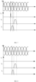
- the preliminary breaking module is configured to enter a preliminary breaking stage after receiving the fault signal, and determine zero-crossing time when the output current of each phase in the three-phase inverter circuit 300 crosses a zero point for a first time.
- the main breaking module is configured to enter a main breaking stage after the preliminary breaking stage, and disconnect, when each phase meets at least one of the following conditions, the relay assembly K of the corresponding phase: A time difference between present time and the zero-crossing time is less than a threshold. Or, the output current is less than a fifth current threshold.
- the preliminary breaking module After receiving the fault signal from the fault detection module, the preliminary breaking module is configured to determine, according to a detection result of the current detection module, the zero-crossing time when the output current of each phase crosses the zero point first.
- the zero-crossing time is a point when the current changes from a positive direction to a negative direction or from the negative direction to the positive direction.
- the main breaking module is configured to disconnect the relay assembly K of the corresponding phase at target time.
- the target time is a point determined according to the zero-crossing time.
- a time difference between the point and the zero-crossing time is less than a preset threshold. This ensures that the relay assembly K is disconnected when the current crosses the zero or approaches the zero, so as to reduce the electric arc and the impact of the current on the relay assembly K.
- the threshold may be selected according to an actual application scenario, and is not limited herein. For example, the threshold may be 0.5 ms.
- the main breaking module is configured to disconnect the relay assembly K of the corresponding phase when the output current is less than the fifth current threshold. This can ensure that the relay assembly K is disconnected when the current approaches the zero.
- the specific value of the fifth current threshold may be selected according to an actual application scenario, and is not limited herein.
- the fifth current threshold may be 0.5A or 0.8A.
- the main breaking module is configured to disconnect the relay assembly K of the corresponding phase at the target time or when the output current is less than the fifth current threshold. This can ensure that the current when the relay assembly is disconnected is relatively small, thereby preventing damage of an impact current on the relay assembly when the relay assembly is disconnected.
- the principle that the relay assembly of the corresponding phase is disconnected when the time difference between the present time and the zero-crossing time is less than the threshold or the output current is less than the fifth current threshold may refer to the foregoing embodiment, and is repeated herein.
- the relay assembly K of the corresponding phase is disconnected at target time or when the output current is less than the fifth current threshold. This can ensure that the current when the relay assembly is disconnected is relatively small, thereby preventing damage of an impact current on the relay assembly when the relay assembly is disconnected.
- FIG. 12 another embodiment of the present disclosure provides a protection circuit applied to a split-phase inverter circuit.
- the protection circuit is similar to the protection circuit applied to the three-phase inverter circuit in terms of the overall architecture, except that the three phases are changed into two phases.
- the bridge arm, the filter inductor L, and the relay assembly are designed in two phases, while the overcurrent detection module and the voltage detection module are the same.
- the specific structure of the protection circuit still includes the controllable power device Q, the fault detection module, the current detection circuit, and the controller.
- the controllable power device Q is in parallel connection with the bridge arm in the three-phase inverter circuit 300. SCRs in the controllable power device Q correspond to output phases of the split-phase inverter circuit.
Landscapes
- Engineering & Computer Science (AREA)
- Power Engineering (AREA)
- Inverter Devices (AREA)
- Supply And Distribution Of Alternating Current (AREA)
Applications Claiming Priority (2)
| Application Number | Priority Date | Filing Date | Title |
|---|---|---|---|
| CN202311774148.6A CN117767408A (zh) | 2023-12-21 | 2023-12-21 | 多相逆变器及电力系统 |
| CN202411106575.1A CN119362361A (zh) | 2024-08-12 | 2024-08-12 | 保护电路、控制方法及光伏系统 |
Publications (2)
| Publication Number | Publication Date |
|---|---|
| EP4576466A2 true EP4576466A2 (de) | 2025-06-25 |
| EP4576466A3 EP4576466A3 (de) | 2025-08-06 |
Family
ID=94323210
Family Applications (1)
| Application Number | Title | Priority Date | Filing Date |
|---|---|---|---|
| EP24221523.4A Pending EP4576466A3 (de) | 2023-12-21 | 2024-12-19 | Schutzschaltung, steuerungsverfahren und fotovoltaisches system |
Country Status (2)
| Country | Link |
|---|---|
| US (1) | US20250210971A1 (de) |
| EP (1) | EP4576466A3 (de) |
Family Cites Families (6)
| Publication number | Priority date | Publication date | Assignee | Title |
|---|---|---|---|---|
| CN105548755B (zh) * | 2015-12-11 | 2018-11-09 | 上能电气股份有限公司 | 通过单一接地绝缘阻抗检测网络检测逆变器交、直流侧接地的方法 |
| CN112234645B (zh) * | 2020-09-02 | 2022-10-04 | 华为数字能源技术有限公司 | 一种功率变换器、光伏发电系统、方法及装置 |
| WO2022126351A1 (zh) * | 2020-12-15 | 2022-06-23 | 华为数字能源技术有限公司 | 一种光伏系统、保护方法及逆变系统 |
| CN113629988B (zh) * | 2021-08-13 | 2023-10-31 | 阳光电源股份有限公司 | 一种pwm整流器及其短路保护装置 |
| CN115664240A (zh) * | 2022-06-22 | 2023-01-31 | 华为数字能源技术有限公司 | 一种逆变器保护装置与光伏系统 |
| CN117039807A (zh) * | 2023-08-11 | 2023-11-10 | 阳光电源股份有限公司 | 一种逆变系统、并网系统及逆变器的保护方法 |
-
2024
- 2024-12-18 US US18/985,112 patent/US20250210971A1/en active Pending
- 2024-12-19 EP EP24221523.4A patent/EP4576466A3/de active Pending
Also Published As
| Publication number | Publication date |
|---|---|
| US20250210971A1 (en) | 2025-06-26 |
| EP4576466A3 (de) | 2025-08-06 |
Similar Documents
| Publication | Publication Date | Title |
|---|---|---|
| US11631973B2 (en) | Adjustable speed drive with integrated solid-state circuit breaker and method of operation thereof | |
| US11532935B2 (en) | Rapid shutdown device for photovoltaic system and control method thereof and protection system | |
| CN104488156B (zh) | 故障排除的方法 | |
| JP5730456B1 (ja) | 電力変換装置 | |
| CN111181416B (zh) | 一种模块化多电平换流器及直流故障清除方法 | |
| WO2013079937A2 (en) | Power converter | |
| CN107534296A (zh) | 双极dc电力传输结构 | |
| WO2016107616A1 (zh) | 一种防止电压源型换流器电容过电压的装置 | |
| EP4047776A1 (de) | Fehlererkennungsvorrichtung und -verfahren, und netzgekoppeltes fotovoltaisches stromerzeugungssystem | |
| CN110535098A (zh) | 一种柔性直流输电系统直流故障的保护方法 | |
| CN119362361A (zh) | 保护电路、控制方法及光伏系统 | |
| CN110739668A (zh) | 一种柔性直流电网短路故障性质判别方法及重合闸方法 | |
| CN117791511A (zh) | 一种功率变换器及其直流侧对地短路的保护方法 | |
| CN112217277B (zh) | Ups主旁路切换系统 | |
| US12244222B2 (en) | Power conversion circuit, power transmission system, and photovoltaic device | |
| CN110672972B (zh) | 一种柔性直流配电网络故障定位和隔离方法 | |
| CN105790238A (zh) | 一种双极mmc-hvdc输电系统及阀侧单相接地故障的保护方法 | |
| US10075091B2 (en) | Power converter | |
| EP4576466A2 (de) | Schutzschaltung, steuerungsverfahren und fotovoltaisches system | |
| CN111682510A (zh) | 用于对称单极直流微网接地故障的先切除后隔离保护方法 | |
| CN117039807A (zh) | 一种逆变系统、并网系统及逆变器的保护方法 | |
| CN115528652A (zh) | Mmc型换流器故障子模块的旁路方法及旁路状态检测方法 | |
| CN108963987B (zh) | 用于直流电网故障限流装置的混合运行控制方法 | |
| CN111404117B (zh) | 隔直装置及其控制方法 | |
| US20240154419A1 (en) | High speed protection for phase balancer with zig-zag transformer |
Legal Events
| Date | Code | Title | Description |
|---|---|---|---|
| PUAI | Public reference made under article 153(3) epc to a published international application that has entered the european phase |
Free format text: ORIGINAL CODE: 0009012 |
|
| STAA | Information on the status of an ep patent application or granted ep patent |
Free format text: STATUS: REQUEST FOR EXAMINATION WAS MADE |
|
| 17P | Request for examination filed |
Effective date: 20241219 |
|
| AK | Designated contracting states |
Kind code of ref document: A2 Designated state(s): AL AT BE BG CH CY CZ DE DK EE ES FI FR GB GR HR HU IE IS IT LI LT LU LV MC ME MK MT NL NO PL PT RO RS SE SI SK SM TR |
|
| PUAL | Search report despatched |
Free format text: ORIGINAL CODE: 0009013 |
|
| AK | Designated contracting states |
Kind code of ref document: A3 Designated state(s): AL AT BE BG CH CY CZ DE DK EE ES FI FR GB GR HR HU IE IS IT LI LT LU LV MC ME MK MT NL NO PL PT RO RS SE SI SK SM TR |
|
| RIC1 | Information provided on ipc code assigned before grant |
Ipc: H02H 3/087 20060101AFI20250627BHEP Ipc: H02H 3/10 20060101ALI20250627BHEP Ipc: H02H 7/122 20060101ALI20250627BHEP Ipc: H02M 1/32 20070101ALI20250627BHEP Ipc: H02H 3/32 20060101ALI20250627BHEP Ipc: H02H 3/34 20060101ALI20250627BHEP Ipc: H02H 3/02 20060101ALN20250627BHEP Ipc: H02H 3/033 20060101ALN20250627BHEP Ipc: H02H 3/24 20060101ALN20250627BHEP |
|
| STAA | Information on the status of an ep patent application or granted ep patent |
Free format text: STATUS: EXAMINATION IS IN PROGRESS |
|
| 17Q | First examination report despatched |
Effective date: 20260120 |