EP4576475A1 - Steuerungsvorrichtung zur verwendung in einem mikronetzsystem, steuerungsverfahren und mikronetzsystem - Google Patents
Steuerungsvorrichtung zur verwendung in einem mikronetzsystem, steuerungsverfahren und mikronetzsystem Download PDFInfo
- Publication number
- EP4576475A1 EP4576475A1 EP24220961.7A EP24220961A EP4576475A1 EP 4576475 A1 EP4576475 A1 EP 4576475A1 EP 24220961 A EP24220961 A EP 24220961A EP 4576475 A1 EP4576475 A1 EP 4576475A1
- Authority
- EP
- European Patent Office
- Prior art keywords
- moment
- point
- threshold
- interconnection
- converters
- Prior art date
- Legal status (The legal status is an assumption and is not a legal conclusion. Google has not performed a legal analysis and makes no representation as to the accuracy of the status listed.)
- Pending
Links
Images




Classifications
-
- H—ELECTRICITY
- H02—GENERATION; CONVERSION OR DISTRIBUTION OF ELECTRIC POWER
- H02J—ELECTRIC POWER NETWORKS; CIRCUIT ARRANGEMENTS OR SYSTEMS FOR SUPPLYING OR DISTRIBUTING ELECTRIC POWER; SYSTEMS FOR STORING ELECTRIC ENERGY
- H02J3/00—Circuit arrangements for AC mains or AC distribution networks
- H02J3/38—Arrangements for feeding a single network from two or more generators or sources in parallel; Arrangements for feeding already energised networks from additional generators or sources in parallel
-
- H—ELECTRICITY
- H02—GENERATION; CONVERSION OR DISTRIBUTION OF ELECTRIC POWER
- H02J—ELECTRIC POWER NETWORKS; CIRCUIT ARRANGEMENTS OR SYSTEMS FOR SUPPLYING OR DISTRIBUTING ELECTRIC POWER; SYSTEMS FOR STORING ELECTRIC ENERGY
- H02J3/00—Circuit arrangements for AC mains or AC distribution networks
- H02J3/001—Arrangements for handling faults or abnormalities, e.g. emergencies or contingencies
-
- H—ELECTRICITY
- H02—GENERATION; CONVERSION OR DISTRIBUTION OF ELECTRIC POWER
- H02J—ELECTRIC POWER NETWORKS; CIRCUIT ARRANGEMENTS OR SYSTEMS FOR SUPPLYING OR DISTRIBUTING ELECTRIC POWER; SYSTEMS FOR STORING ELECTRIC ENERGY
- H02J3/00—Circuit arrangements for AC mains or AC distribution networks
- H02J3/001—Arrangements for handling faults or abnormalities, e.g. emergencies or contingencies
- H02J3/0012—Arrangements for handling faults or abnormalities, e.g. emergencies or contingencies characterised by the contingency detection means in AC networks, e.g. using phasor measurement units [PMU], synchrophasors or contingency analysis
-
- H—ELECTRICITY
- H02—GENERATION; CONVERSION OR DISTRIBUTION OF ELECTRIC POWER
- H02J—ELECTRIC POWER NETWORKS; CIRCUIT ARRANGEMENTS OR SYSTEMS FOR SUPPLYING OR DISTRIBUTING ELECTRIC POWER; SYSTEMS FOR STORING ELECTRIC ENERGY
- H02J3/00—Circuit arrangements for AC mains or AC distribution networks
- H02J3/38—Arrangements for feeding a single network from two or more generators or sources in parallel; Arrangements for feeding already energised networks from additional generators or sources in parallel
- H02J3/381—Dispersed generators
-
- H—ELECTRICITY
- H02—GENERATION; CONVERSION OR DISTRIBUTION OF ELECTRIC POWER
- H02J—ELECTRIC POWER NETWORKS; CIRCUIT ARRANGEMENTS OR SYSTEMS FOR SUPPLYING OR DISTRIBUTING ELECTRIC POWER; SYSTEMS FOR STORING ELECTRIC ENERGY
- H02J3/00—Circuit arrangements for AC mains or AC distribution networks
- H02J3/38—Arrangements for feeding a single network from two or more generators or sources in parallel; Arrangements for feeding already energised networks from additional generators or sources in parallel
- H02J3/388—Arrangements for the handling of islanding, e.g. for disconnection or for avoiding the disconnection of power
-
- H—ELECTRICITY
- H02—GENERATION; CONVERSION OR DISTRIBUTION OF ELECTRIC POWER
- H02J—ELECTRIC POWER NETWORKS; CIRCUIT ARRANGEMENTS OR SYSTEMS FOR SUPPLYING OR DISTRIBUTING ELECTRIC POWER; SYSTEMS FOR STORING ELECTRIC ENERGY
- H02J2105/00—Networks for supplying or distributing electric power characterised by their spatial reach or by the load
- H02J2105/10—Local stationary networks having a local or delimited stationary reach
Definitions
- This application relates to the energy field, and more specifically, to a control apparatus used in a microgrid system, a control method, and a microgrid system.
- a microgrid is a small power supply network that mainly uses distributed power supplies and uses energy storage and control apparatuses to perform real-time adjustment to balance electric power and energy inside the microgrid.
- the microgrid has two operating modes: on-grid and off-grid.
- the on-grid mode means that in a normal case, the microgrid operates in connection to a large grid to supply surplus electric energy to the large grid, or the large grid supplies power to a local load and charges a battery.
- the off-grid mode means that when it is detected that the large grid is faulty or electric energy quality does not meet requirements, the microgrid is disconnected from the large grid to form an islanding state, and the distributed power supplies and an energy storage battery in the microgrid supply power to the local load.
- a microgrid system may be affected by an unexpected event like fluctuation/a fault of an external grid, and incorrect switching of the on/off-grid operating mode may occur.
- frequent incorrect switching shortens a service life of a point of interconnection switch, and increases operating costs of the microgrid.
- This application provides a control apparatus used in a microgrid system, a control method, and a microgrid system, so that when a microgrid faces different external grid faults, continuous stability of the microgrid can be ensured by using a proper on/off-grid switching technology.
- a control apparatus used in a microgrid system includes the control apparatus, a microgrid bus, a point of interconnection switch, and M converters, where M ⁇ 1, the control apparatus is configured to communicatively connect to the at least one converter and the point of interconnection switch, and the microgrid bus is configured to connect to an external grid via the point of interconnection switch.
- the control apparatus is configured to: in response to that a fluctuation amplitude of electrical data that is detected at a point of interconnection at a first moment and that is relative to a reference value is greater than or equal to a first threshold, detect electrical data at the point of interconnection at a second moment, where the second moment is later than the first moment.
- the control apparatus is further configured to: in response to that a fluctuation amplitude of the electrical data that is detected at the point of interconnection at the second moment and that is relative to the reference value is less than the first threshold, and a quantity of converters operating in a voltage source mode at a third moment is greater than or equal to a second threshold, control the point of interconnection switch to be turned off, and control the M converters to operate in the voltage source mode, where the third moment is later than the second moment.
- the control apparatus is further configured to: in response to that the fluctuation amplitude of the electrical data that is detected at the point of interconnection at the second moment and that is relative to the reference value is less than the first threshold, and the quantity of converters operating in the voltage source mode at the third moment is less than the second threshold, control the point of interconnection switch to be turned on, and control the M converters to operate in a current source mode.
- the microgrid system is connected in parallel to the external grid and operates, that is, the point of interconnection switch is in a turn-on state, and all the M converters in the on-grid system operate in the current source mode.
- the reference value is the electrical data at the point of interconnection when the microgrid system is connected in parallel to the external grid and operates normally, and the fluctuation amplitude of the electrical data relative to the reference value is a difference between actual electrical data at the point of interconnection and the reference value at a same moment (for example, the first moment).
- the M converters are power supply devices that have the voltage source mode and the current source mode, and can perform mode switching.
- the converter can automatically detect a fault or an exception at an alternating current end of the converter, and when a set condition is met, automatically switches from the current source mode to the voltage source mode.
- control apparatus can determine operating modes of the M converters through communicatively connecting to the M converters, and the control apparatus can control turn-on and turn-off of the point of interconnection switch and the operating modes of the M converters through communication connections.
- control apparatus may be an integrated control apparatus, or the control apparatus includes a plurality of control units with different functions. This is not limited in this embodiment of this application.
- the electrical data at the point of interconnection includes at least one of a current, a voltage, or a frequency at the point of interconnection.
- an interval between the first moment and the second moment is not limited in this embodiment of this application.
- the interval between the first moment and the second moment is 200 milliseconds (ms).
- an interval between the first moment and the third moment is not limited in this embodiment of this application.
- the interval between the first moment and the third moment is 300 milliseconds.
- control apparatus controls the M converters to operate in the voltage source mode can be understood as that the control apparatus sends a first signal to the M converters, or the control apparatus sends a first signal to a converter that is in the M converters and that does not switch to the voltage source mode, where the first signal indicates the converter to operate in the voltage source mode.
- the control apparatus in response to that the fluctuation amplitude of the electrical data that is detected by the control apparatus at the point of interconnection at the first moment and that is relative to the reference value is greater than or equal to the first threshold, the control apparatus detects the fluctuation amplitude of the electrical data at the point of interconnection at the second moment. Further, in response to that the fluctuation amplitude of the electrical data at the point of interconnection at the second moment relative to the reference value is less than the first threshold, and the quantity of converters operating in the voltage source mode in the microgrid system at the third moment is greater than or equal to the second threshold, the control apparatus controls a microgrid to operate off-grid; otherwise, controls the microgrid to maintain on-grid operation.
- control apparatus may determine a fault status of the external grid with reference to the fluctuation amplitude of the electrical data at the point of interconnection at the second moment relative to the reference value and the quantity of converters operating in the voltage source mode at the third moment, to improve accuracy of detecting the fault of the external grid, and in this way, when the microgrid faces different external grid faults, a proper on/off-grid switching technology can be used to ensure continuous stability of the microgrid.
- control apparatus is further configured to: in response to that the fluctuation amplitude of the electrical data that is detected at the point of interconnection at the second moment and that is relative to the reference value is greater than or equal to the first threshold, control the point of interconnection switch to be turned off, and control the M converters to operate in the voltage source mode.
- the control apparatus in response to that the fluctuation amplitude of the electrical data detected at the point of interconnection at the second moment is greater than or equal to the first threshold, the control apparatus may control the point of interconnection switch to be turned off, and control the at least one converter to operate in the voltage source mode. In this way, when a fault of the external grid is a non-temporary fault, correct off-grid of the microgrid system can be ensured.
- control apparatus is further configured to: in response to that the quantity of converters operating in the voltage source mode at the third moment is less than the second threshold and greater than or equal to a third threshold, send an indication signal to at least one of the M converters, where the indication signal indicates the at least one converter to change output electrical data, and the third threshold is less than the second threshold.
- control apparatus is further configured to: in response to that the quantity of converters operating in the voltage source mode at the third moment is less than a third threshold, control the point of interconnection switch to be turned on, and control the M converters to operate in the current source mode.
- the control apparatus may determine, by detecting the electrical data at the point of interconnection, whether the microgrid system is off-grid. Further, in response to that the microgrid system operates in an off-grid mode, the control apparatus is configured to: control the point of interconnection switch to be turned off, and control the M converters to operate in the voltage source mode; and in response to that the microgrid system operates in an on-grid mode, the control apparatus is configured to control the point of interconnection switch to be turned on, and control the M converters to operate in the current source mode.
- the at least one converter changes the output voltage. If the control apparatus detects that the fluctuation of the voltage of the point of interconnection switch exceeds the threshold, the control apparatus indicates the point of interconnection switch to be turned off, and indicates the at least one converter to switch to the voltage source mode.
- the control apparatus can, in response to that the fluctuation amplitude of the electrical data that is detected at the point of interconnection at the second moment and that is relative to the reference value is less than the first threshold, and the quantity of converters operating in the voltage source mode at the third moment is less than the second threshold and greater than or equal to the third threshold, indicate, by using an instruction signal, the at least one converter to change output electrical data to perform overall active anti-islanding protection of the microgrid, to determine, based on a detection result of the anti-islanding protection, whether to perform on/off-grid switching, thereby improving real-time performance and reliability of the on/off-grid switching of the microgrid system.
- control apparatus is further configured to: in response to that the fluctuation amplitude of the electrical data that is detected at the point of interconnection at the first moment and that is relative to the reference value is greater than or equal to a fourth threshold, control the point of interconnection switch to be turned off, and control the M converters to operate in the voltage source mode, where the fourth threshold is greater than the first threshold.
- the control apparatus controls the point of interconnection switch to be turned off, and controls the M converters to operate in the voltage source mode. In this way, when a serious fault occurs in the external grid, the microgrid system can be controlled to quickly switch to the off-grid mode.
- control apparatus is configured to: continuously detect the electrical data at the point of interconnection between the first moment and the second moment, and/or continuously detect operating modes of the M converters between the second moment and the third moment.
- control apparatus detects, at any moment of continuous detection, that the fluctuation amplitude of the electrical data at the point of interconnection is greater than or equal to the fourth threshold, the control apparatus controls the point of interconnection switch to be turned off, and controls the M converters to operate in the voltage source mode.
- the control apparatus includes a first control unit and a second control unit.
- the first control unit is configured to communicatively connect to the point of interconnection switch, and the second control unit is configured to communicatively connect to the M converters.
- the first control unit is configured to detect the electrical data at the point of interconnection, and the second control unit is configured to detect the operating modes of the M converters.
- the first control unit and the second control unit are communicatively connected.
- a control method includes: in response to that a fluctuation amplitude of electrical data that is detected at a point of interconnection at a first moment and that is relative to a reference value is greater than or equal to a first threshold, detecting electrical data at the point of interconnection at a second moment, where the second moment is later than the first moment.
- the method further includes: in response to that a fluctuation amplitude of the electrical data that is detected at the point of interconnection at the second moment and that is relative to the reference value is less than the first threshold, and a quantity of converters operating in a voltage source mode at a third moment is greater than or equal to a second threshold, controlling a point of interconnection switch to be turned off, and controlling M converters to operate in the voltage source mode, where the third moment is later than the second moment.
- the method further includes: in response to that the fluctuation amplitude of the electrical data that is detected at the point of interconnection at the second moment and that is relative to the reference value is less than the first threshold, and the quantity of converters operating in the voltage source mode at the third moment is less than the second threshold, controlling the point of interconnection switch to be turned on, and controlling the M converters to operate in a current source mode.
- the M converters are connected to an external grid via the point of interconnection switch.
- the method further includes: in response to that the fluctuation amplitude of the electrical data that is detected at the point of interconnection at the second moment and that is relative to the reference value is greater than or equal to the first threshold, controlling the point of interconnection switch to be turned off, and controlling the M converters to operate in the voltage source mode.
- the method further includes: in response to that the quantity of converters operating in the voltage source mode at the third moment is less than the second threshold and greater than or equal to a third threshold, sending an indication signal to at least one of the M converters, where the indication signal indicates the at least one converter to change output electrical data, and the third threshold is less than the second threshold.
- the method further includes: in response to that the fluctuation amplitude of the electrical data detected at the point of interconnection at the first moment is greater than or equal to a fourth threshold, controlling the point of interconnection switch to be turned off, and controlling the M converters to operate in the voltage source mode, where the fourth threshold is greater than the first threshold.
- the method further includes: in response to that the fluctuation amplitude of the electrical data that is detected at the point of interconnection at the first moment and that is relative to the reference value is greater than or equal to a fourth threshold, controlling the point of interconnection switch to be turned off, and controlling the M converters to operate in the voltage source mode, where the fourth threshold is greater than the first threshold.
- a control apparatus used in a microgrid system includes the control apparatus, a microgrid bus, a point of interconnection switch, and M converters, where M ⁇ 1, the control apparatus is configured to communicatively connect to the at least one converter and the point of interconnection switch, and the microgrid bus is configured to connect to an external grid via the point of interconnection switch.
- the control apparatus is configured to: in response to that it is detected, at a first moment, that an operating mode of at least one of the M converters changes, detect electrical data at a point of interconnection at a second moment, where the second moment is later than the first moment.
- the control apparatus is further configured to: in response to that a fluctuation amplitude of the electrical data that is detected at the point of interconnection at the second moment and that is relative to a reference value is less than a first threshold, and a quantity of converters operating in a voltage source mode at a third moment is greater than or equal to a second threshold, control the point of interconnection switch to be turned off, and control the M converters to operate in the voltage source mode, where the third moment is later than the second moment.
- the control apparatus is further configured to: in response to that a fluctuation amplitude of the electrical data that is detected at the point of interconnection at the second moment and that is relative to a reference value is less than a first threshold, and a quantity of converters operating in a voltage source mode at a third moment is less than a second threshold, control the point of interconnection switch to be turned on, and control the M converters to operate in a current source mode.
- a control method includes: in response to that it is detected, at a first moment, that an operating mode of at least one of M converters changes, detecting electrical data at a point of interconnection at a second moment, where the second moment is later than the first moment.
- the method further includes: in response to that a fluctuation amplitude of the electrical data that is detected at the point of interconnection at the second moment and that is relative to a reference value is less than a first threshold, and a quantity of converters operating in a voltage source mode at a third moment is greater than or equal to a second threshold, controlling a point of interconnection switch to be turned off, and controlling M converters to operate in the voltage source mode, where the third moment is later than the second moment.
- the method further includes: in response to that a fluctuation amplitude of the electrical data that is detected at the point of interconnection at the second moment and that is relative to a reference value is less than a first threshold, and a quantity of converters operating in a voltage source mode at a third moment is less than a second threshold, controlling the point of interconnection switch to be turned on, and controlling the M converters to operate in a current source mode.
- the M converters are connected to an external grid via the point of interconnection switch.
- a microgrid system including the control apparatus according to the first aspect or any implementation of the first aspect, a microgrid bus, a point of interconnection switch, M converters, and at least one load, where M ⁇ 1, the control apparatus is configured to communicatively connect to the M converters and the point of interconnection switch, the microgrid bus is configured to connect to an external grid via the point of interconnection switch, and the control apparatus is configured to: in response to that a fluctuation amplitude of electrical data that is detected at a point of interconnection at a first moment and that is relative to a reference value is greater than or equal to a first threshold, detect electrical data at the point of interconnection at a second moment, where the second moment is later than the first moment.
- the control apparatus is further configured to: in response to that a fluctuation amplitude of the electrical data that is detected at the point of interconnection at the second moment and that is relative to the reference value is less than the first threshold, and a quantity of converters operating in a voltage source mode at a third moment is greater than or equal to a second threshold, control the point of interconnection switch to be turned off, and control the M converters to operate in the voltage source mode, where the third moment is later than the second moment.
- the control apparatus is further configured to: in response to that the fluctuation amplitude of the electrical data that is detected at the point of interconnection at the second moment and that is relative to the reference value is less than the first threshold, and the quantity of converters operating in the voltage source mode at the third moment is less than the second threshold, control the point of interconnection switch to be turned on, and control the M converters to operate in a current source mode.
- control apparatus is further configured to: in response to that the fluctuation amplitude of the electrical data that is detected at the point of interconnection at the second moment and that is relative to the reference value is greater than or equal to the first threshold, control the point of interconnection switch to be turned off, and control the M converters to operate in the voltage source mode.
- Microgrid is a small power supply network that mainly uses distributed power supplies and uses energy storage and control apparatuses to perform real-time adjustment to balance electric power and energy inside the microgrid.
- the microgrid may operate in connection to an external grid or operate independently off the grid.
- a system 100 includes an external grid 110 and a microgrid 120.
- the microgrid 120 is connected to the external grid 110 via a point of interconnection switch 121.
- the point of interconnection switch 121 When the point of interconnection switch 121 is in an on state, the microgrid 120 may be connected to the external grid (for example, a three-phase alternating current grid or a direct current grid). After the connection, the microgrid 120 may supply power to devices inside the microgrid or supply power to the external grid 110.
- the microgrid 120 when the point of interconnection switch 121 is in the on state, the microgrid 120 is connected to the external grid 110. In this case, the microgrid is in an on-grid operating mode. When the point of interconnection switch 121 is in an off state, the microgrid 120 is disconnected from the external grid 110. In this case, the microgrid is in an off-grid operating mode, which is also referred to as an islanding operating mode or an islanding state.
- the on-grid operating mode is an operating mode in which a power conversion system is connected to an alternating current grid synchronously, operates with a current source characteristic, and stores electric energy of the grid in a battery string or feeds energy of the battery string back to the grid.
- a PQ control manner is usually used for the power conversion system in the on-grid operating mode. In this control manner, the power conversion system is controlled to output a constant power, and reactive power and active power of the power conversion system are controllable.
- the off-grid operating mode is an operating mode in which the power conversion system operates with a voltage source characteristic to supply power to an alternating current side of an energy storage system or a connected grid.
- the power conversion system in the off-grid operating mode operates in a virtual synchronous generator (virtual synchronous generator, VSG) mode.
- VSG virtual synchronous generator
- the VSG is an operation technology in which a mathematical model of a synchronous generator is embedded into a control algorithm of an inverter, and a static power electronic apparatus is simulated as a rotating motor, and the VSG has functions of a damping voltage, frequency rapid fluctuation, automatic power distribution, and synchronous grid operation by simulating primary frequency regulation and voltage regulation of the synchronous generator.
- the power conversion system is a converter that implements bidirectional conversion of electric energy in an electrochemical energy storage system, is connected between a battery system and a grid and/or a load, and may directly supply power to an alternating current load when there is no grid.
- the PCS includes a converter and a control unit.
- the PCS may control a charging and discharging process of the battery system.
- the control unit of the PCS receives a background control instruction through communication, and controls, based on a symbol and a value of the power instruction, the converter to perform charging or discharging on the battery system, to adjust active power and reactive power of the grid.
- the control unit of the PCS communicates with a battery management system (battery management system, BMS) through a controller area network (Controller Area Network, CAN) interface, to obtain battery string status information, so as to implement protective charging and discharging on the battery and ensure safe operation of the battery.
- BMS battery management system
- CAN Controller Area Network
- a microgrid system of AC coupling of PV and ESS may be affected by an unexpected event like a fluctuation or a fault from outside of the grid. Therefore, in the microgrid system, a proper on/off-grid switching technology needs to be used to isolate disturbance from outside of the grid, to ensure continuous operation of the internal system of the microgrid.
- the on/off-grid switching technology is a key technology of the microgrid system and directly affects off-grid switching effect of the microgrid.
- an unplanned off-grid switching process of the microgrid mainly includes the following steps: 1. Detect an exception. 2. Turn off a point of interconnection (point of interconnection, POI) switch. 3. The power conversion system inside the microgrid switches from a current source mode to a voltage source mode. 4. A microgrid central controller (Micro grid Central Controller, MGCC) performs off-grid control.
- MGCC Micro grid Central Controller
- the off-grid switching solution in the industry is mainly used to improve a speed or smoothness of switching a control algorithm by the power conversion system PCS in a scenario in which the microgrid or the distributed power supply is open-circuited.
- the microgrid is prone to disturbance or even false disturbance of an external grid and performs off-grid switching. This shortens a service life of the point of interconnection switch, increases an overhauling frequency for operation and maintenance, and increases operation costs of the microgrid system.
- whether the PCS switches to an off-grid mode is determined based on a fault ride-through curve of the grid. Specifically, the PCS detects, in real time, a change of a voltage of a large grid connected to the PCC. When the voltage of the large grid drops and drop time and a voltage amplitude meet a low voltage ride-through condition, the PCS maintains the on-grid operation and provides specific reactive power for the large grid to support recovery of the large grid. When the voltage of the large grid drops and the drop time and the voltage amplitude do not meet the low voltage ride-through condition, the power conversion system switches to off-grid operation to provide reliable electric energy power for a local load.
- this solution is a solution on a power station side, and cannot effectively identify and adapt to fault switching in a scenario in which a power distribution network (for example, a microgrid) is connected.
- a power distribution network for example, a microgrid
- this solution is a solution on a power station side, and cannot effectively identify and adapt to fault switching in a scenario in which a power distribution network (for example, a microgrid) is connected.
- a power distribution network for example, a microgrid
- embodiments of this application provide a control apparatus used in a microgrid system, a control method, and a microgrid system, to improve accuracy of detecting a fault of an external grid by a microgrid, so that the microgrid is correctly off-grid when encountering an external permanent fault, and the microgrid does not need to be forced to disconnect from the main grid when a short-time or transient minor fault occurs, thereby reducing incorrect switching, ensuring continuous stability of the microgrid, and ensuring cost-effectiveness of the microgrid system.
- FIG. 2 is a diagram of an architecture of a microgrid system to which an embodiment of this application is applicable.
- the system includes a control apparatus 210, a point of interconnection switch 220, a plurality of converters, another power supply 230 (for example, photovoltaic power generation), and a load 240.
- One end of the point of interconnection switch 220 is connected to an alternating current bus #2 of a grid through a switch 250 on a transmission line path, and the alternating current bus #2 is connected to the upper-level grid.
- the other end of the point of interconnection switch 220 is connected to an alternating current bus #1, and the alternating current bus #1 is connected to a converter #1, a converter #2, ..., a converter #n, and the like.
- One end of the converter #1 is connected to the alternating current bus #1 via a switch, and the other end of the converter #1 is connected to an energy storage unit #1.
- One end of the converter #2 is connected to the alternating current bus #1 via a switch, and the other end of the converter #2 is connected to an energy storage unit #2.
- One end of the converter #n is connected to the alternating current bus #1 via a switch, and the other end of the converter #n is connected to an energy storage unit #n.
- control apparatus 210 is communicatively connected to each converter, to monitor an operating mode of the converter.
- control apparatus 210 is further communicatively connected to the point of interconnection switch 220, to monitor turn-on and turn-off of the point of interconnection switch 220.
- control apparatus is usually communicatively connected to another voltage in the system.
- control apparatus is usually communicatively connected to another voltage in the system.
- control apparatus may be a single integrated system control apparatus, for example, a microgrid control apparatus used for fault detection at the point of interconnection, or may be a control apparatus with independent functions, for example, a combination of a microgrid control apparatus and a comprehensive protection device (a comprehensive protection device or a relay protection device) at the point of interconnection. This is not limited in this embodiment of this application.
- the plurality of converters are power supply devices that have a voltage source mode and a current source mode, and can perform mode switching.
- the plurality of converters can automatically detect a fault or an exception at an alternating current end of the converters, and when a set condition is met, automatically switches from the current source mode to the voltage source mode.
- the converter operates in the current source mode in an on-grid mode, and the converter operates in the voltage source mode in an off-grid mode.
- the control apparatus 210 detects electrical data at the point of interconnection at a moment T 1 (namely, a second moment).
- control apparatus 210 may continuously detect the electrical data at the point of interconnection within the interval between the moment T 0 and the moment T 1 , or the control apparatus may detect only the electrical data at the point of interconnection at the moment T 1 . This is not limited in this embodiment of this application.
- S340 The control apparatus 210 determines whether a fluctuation amplitude of the electrical data at the point of interconnection at the moment T 1 meets the startup delay condition.
- step S350 If the fluctuation amplitude of the electrical data at the moment T 1 meets the startup delay condition, step S350 is performed, so that the microgrid system switches to an off-grid operating state; or if the fluctuation amplitude of the electrical data at the moment T 1 does not meet the startup delay condition, step S360 is performed, so that the microgrid system recovers to an on-grid operating state.
- step S340 the control apparatus 210 determines whether a fault of the external grid persists by determining whether the fluctuation amplitude of the electrical data at the point of interconnection at the moment T 1 is greater than the threshold #1, and further performs a subsequent step to control the off/on-grid switching of the microgrid system.
- the control apparatus 210 indicates a point of interconnection switch 220 to be turned off, and indicates the converter in the microgrid system to operate in the voltage source mode.
- control apparatus 210 sends a first signal to the point of interconnection switch, and sends a second signal to the converter inside the microgrid system.
- the first signal indicates the point of interconnection switch to be turned off (or the point of interconnection switch is turned off), and the second signal indicates the converter to operate in the voltage source mode.
- control apparatus 210 may send the second signal to all converters in the microgrid system, or the control apparatus 210 sends the second signal only to a converter that operates in the current source mode in the microgrid system. This is not limited in this application.
- the microgrid system includes only two converters, and the control apparatus 210 determines that a converter #1 in the microgrid system switches to the voltage source mode at the moment T 1 , and a converter #2 still operates in the current source mode.
- the control apparatus 210 may send the second signal to both the converter #1 and the converter #2, or the control apparatus 210 may send the second signal only to the converter #2.
- the converter that receives the second signal operates in the voltage source mode.
- the control apparatus 210 detects a quantity of converters operating in the voltage source mode at a moment T 2 (namely, a third moment).
- control apparatus 210 may determine the operating mode of the converter in the microgrid system through a communication connection, to determine the quantity of converters operating in the voltage source mode in the microgrid system.
- the moment T 2 is later than the moment T 1 , and a specific value of an interval between the moment T 0 and the moment T 2 is not limited in this embodiment of this application.
- the interval between the moment T 0 and the moment T 2 is 300 milliseconds (ms).
- the control apparatus 210 determines whether the quantity of converters operating in the voltage source mode at the moment T 2 is greater than a threshold #2 (namely, a second threshold).
- step S350 if the quantity of converters operating in the voltage source mode at the moment T 2 is greater than or equal to the threshold #2, the control apparatus 210 performs step S350; or if the quantity of converters operating in the voltage source mode at the moment T 2 is less than the threshold #2, the control apparatus 210 performs step S380.
- control apparatus 210 may further determine severity of the fault in the external grid based on a relationship between the quantity of converters operating in the voltage source mode at the moment T 2 and the threshold #2, to improve accuracy of detecting the fault in the external grid by the control apparatus 210.
- the control apparatus 210 indicates the converter to operate in the current source mode.
- this step is used to maintain on-grid operation of the microgrid system.
- the control apparatus 210 controls the point of interconnection switch to remain on, and sends a third signal to the converter in the microgrid system.
- the third signal indicates the converter to operate in the current source mode, or the third signal indicates the converter to recover to an on-grid mode.
- control apparatus 210 may send the third signal to all the converters in the microgrid system, to indicate all the converters to operate in the current source mode.
- control apparatus 210 sends the third signal to a converter that switches to the voltage source mode in the microgrid system, to indicate the converter operating in the voltage source mode to switch to the current source mode. This is not limited in this application.
- the threshold #2 is 3, and the control apparatus 210 determines that the converter #1 and the converter #2 in the microgrid system switch to the voltage source mode before the moment T 2 .
- the control apparatus 210 sends the third signal to the converter #1 and the converter #2.
- the third signal indicates the converter #1 and the converter #2 to switch to the current source mode.
- the converter #1 and the converter #2 switch to the current source mode in response to the third signal.
- a specific value of the threshold #2 is not limited in this embodiment of this application, and may be determined based on a specific requirement of the microgrid system. In an example, when the requirement of the microgrid system is sensitive on/off-grid switching, a small threshold #2 may be set. In another example, the requirement of the microgrid system is on/off-grid switching with strong anti-disturbance, and a large threshold #2 may be set.
- the control apparatus 210 may determine a fault status of the external grid based on the two set delays (namely, the moment T 1 and the moment T 2 ) with reference to the fluctuation amplitude of the electrical data at the point of interconnection at the moment T 1 and the quantity of converters operating in the voltage source mode at the moment T 2 , to improve accuracy of detecting the fault of the external grid by the microgrid system, and in this way, the microgrid system does not directly switch to the off-grid mode due to minor fault disturbance of the grid.
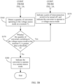
- steps S370 and S380 are further included.
- the control apparatus 210 determines whether the quantity of converters operating in the voltage source mode at the moment T 2 is greater than or equal to a threshold #3 (namely, a third threshold). The threshold #3 is less than the threshold #2.
- step S372 is performed; or if the quantity of converters operating in the voltage source mode is less than the threshold #3, step S380 is performed.
- the control apparatus 210 performs overall anti-islanding of the microgrid, and performs off-grid operation or recovers on-grid operation based on a result.
- control apparatus 210 performs overall anti-islanding of the microgrid is not limited in this application.
- control apparatus 210 sends an indication signal to the converter, where the indication signal indicates the converter to change an output voltage.
- the control apparatus 210 determines, based on whether it is detected that fluctuation of a voltage of the point of interconnection switch exceeds a preset threshold, whether the entire microgrid system is off-grid.
- control apparatus 210 sends the indication signal to the converter, where the indication signal indicates the converter to change an output frequency.
- the control apparatus 210 determines, based on whether it is detected that fluctuation of a frequency of the point of interconnection switch exceeds the preset threshold, whether the entire microgrid system is off-grid.
- step S350 is performed; or if the control apparatus 210 determines that the microgrid system is not off-grid, step S380 is performed to recover on-grid operation.
- control apparatus 210 may perform overall anti-islanding protection for the microgrid when the quantity of converters operating in the voltage source mode at the moment T 2 is between the threshold #2 and the threshold #3, and determine, based on a detection result of the anti-islanding protection, whether to perform on/off-grid switching, thereby improving real-time performance and reliability of the on/off-grid switching of the microgrid system.
- FIG. 4A and FIG. 4B are a diagram of an on/off-grid switching method 400 according to an embodiment of this application. As shown in the figure, the method 400 includes the following steps.
- a control apparatus 210 detects electrical data at a point of interconnection and an operating mode of a converter in a microgrid system.
- control apparatus detects the electrical data at the point of interconnection and the operating mode of the converter in the microgrid system, refer to related content in S310. Details are not described herein again.
- the control apparatus 210 determines whether a fluctuation amplitude of the electrical data at the point of interconnection meets a direct off-grid condition or a startup delay condition.
- the direct off-grid may include that the fluctuation amplitude of the electrical data at the point of interconnection reaches a preset threshold #4 (namely, an example of a fourth threshold), and the startup delay condition may include that the fluctuation amplitude of the electrical data at the point of interconnection reaches a preset threshold #1.
- a case in which the direct off-grid condition is met corresponds to a case in which a serious fault occurs in an external grid, that is, the threshold #4 is greater than the threshold #1.
- a normal operating voltage at the point of interconnection is 1 kV
- the threshold #1 may be 0.3 kV
- the threshold #4 may be 0.5 kV
- step S430 If the fluctuation amplitude of the electrical data at the point of interconnection meets the direct off-grid condition, step S430 is performed, so that quick off-grid can be implemented when a serious fault occurs in the external grid; if the fluctuation amplitude of the electrical data at the point of interconnection meets only the startup delay condition, step S440 is performed; or if the fluctuation amplitude of the electrical data at the point of interconnection does not meet the direct off-grid condition or the startup delay condition, step S410 is performed.
- the control apparatus uses the current moment as a moment T 0 (namely, a first moment).
- the control apparatus 210 indicates a point of interconnection switch 220 to be turned off, and indicates the converter to switch to a voltage source mode.
- control apparatus sends a first signal to the point of interconnection switch, and sends a second signal to a plurality of converters inside the microgrid system.
- the first signal indicates the point of interconnection switch to be turned off (or the point of interconnection switch is turned off), and the second signal indicates the converter to operate in the voltage source mode.
- the control apparatus 210 detects electrical data at the point of interconnection at a moment T 1 (namely, a second moment).
- the control apparatus 210 detects a quantity of converters operating in the voltage source mode at a moment T 2 (namely, a third moment).
- the control apparatus 210 determines whether the quantity of converters operating in the voltage source mode at the moment T 2 is greater than the threshold #2 (namely, a second threshold).
- the control apparatus 210 indicates the converter to operate in the current source mode.
- the control apparatus 210 performs overall anti-islanding of the microgrid, and performs off-grid operation or recovers on-grid operation based on a result.
- the overall anti-islanding of the microgrid refer to related content in step S372. Details are not described herein again.
- the system includes a control apparatus 511, a control apparatus 512, a point of interconnection switch 520, a plurality of converters, another power supply 530 (for example, photovoltaic power generation), and a load.
- a separate control apparatus 512 is disposed in the architecture in the figure to connect to the point of interconnection switch. Specifically, one end of the control apparatus 512 is connected to the point of interconnection switch, and the other end of the control apparatus 512 is connected to the control apparatus 511.
- FIG. 3A and FIG. 3B and FIG. 4A and FIG. 4B are also applicable to the system architecture in FIG. 5 .
- the following uses an example in which the method shown in FIG. 3A and FIG. 3B is applied to the architecture shown in FIG. 5 for description.
- the control apparatus 511 controls an operating mode of at least one converter, and the control apparatus 512 detects electrical data at a point of interconnection.
- the control apparatus 512 determines whether a fluctuation amplitude of the electrical data at the point of interconnection meets a startup delay condition. If the fluctuation amplitude of the electrical data at the point of interconnection meets the startup delay condition, the control apparatus 512 uses the current moment as a moment T 0 , and performs step S630; or if the fluctuation amplitude of the electrical data at the point of interconnection does not meet the startup delay condition, performs step S610.
- the control apparatus 512 detects electrical data at the point of interconnection at a moment T 1 (namely, a second moment).
- the control apparatus 512 determines whether a fluctuation amplitude of the electrical data at the point of interconnection at the moment T 1 meets the startup delay condition.
- step S650 is performed, so that the microgrid system switches to an off-grid operating state; or if the fluctuation amplitude of the electrical data at the moment T 1 does not meet the startup delay condition, step S660 is performed, to further determine, with reference to a quantity of converters switching to the voltage source mode in the microgrid system, whether the microgrid system is off-grid.
- the control apparatus 511 indicates the converter to switch to the voltage source mode, and the control apparatus 512 indicates the point of interconnection switch 520 to be turned off.
- control apparatus 512 sends a first signal to the point of interconnection switch, and the control apparatus 511 sends a second signal to the plurality of converters inside the microgrid system.
- the first signal indicates the point of interconnection switch to be turned off (or the point of interconnection switch is turned off), and the second signal indicates the converter to switch to the voltage source mode.
- control apparatus 511 and the control apparatus 512 separately send the signal
- an occasion for collaboratively sending the signal may be implemented through a communication connection in advance. This is not limited in this embodiment of this application.
- the control apparatus 511 detects a quantity of converters operating in the voltage source mode at a moment T 2 (namely, a third moment).
- control apparatus 511 may notify the control apparatus 512 through the communication connection.
- the control apparatus 511 determines whether the quantity of converters switching to the voltage source mode at the moment T 2 is greater than a threshold #2 (namely, a second threshold).
- control apparatus 512 and the control apparatus 511 perform step S650; or if the quantity of converters operating in the voltage source mode at the moment T 2 is less than the threshold #2, the control apparatus 511 performs step S670.
- the control apparatus 511 indicates the converter to operate in a current source mode.
- this step is used to maintain on-grid operation of the microgrid system.
- the control apparatus 512 controls the point of interconnection switch to remain on, and the control apparatus 511 sends a third signal to the converter in the microgrid system.
- the third signal indicates the converter to switch to the current source mode, the third signal indicates the converter to operate in the current source mode, or the third signal indicates the converter to recover to an on-grid mode.
Landscapes
- Engineering & Computer Science (AREA)
- Power Engineering (AREA)
- Inverter Devices (AREA)
Applications Claiming Priority (1)
| Application Number | Priority Date | Filing Date | Title |
|---|---|---|---|
| CN202311749727.5A CN117937590A (zh) | 2023-12-18 | 2023-12-18 | 用于微电网系统的控制装置,控制方法和微电网系统 |
Publications (1)
| Publication Number | Publication Date |
|---|---|
| EP4576475A1 true EP4576475A1 (de) | 2025-06-25 |
Family
ID=90758416
Family Applications (1)
| Application Number | Title | Priority Date | Filing Date |
|---|---|---|---|
| EP24220961.7A Pending EP4576475A1 (de) | 2023-12-18 | 2024-12-18 | Steuerungsvorrichtung zur verwendung in einem mikronetzsystem, steuerungsverfahren und mikronetzsystem |
Country Status (3)
| Country | Link |
|---|---|
| US (1) | US20250202241A1 (de) |
| EP (1) | EP4576475A1 (de) |
| CN (1) | CN117937590A (de) |
Families Citing this family (2)
| Publication number | Priority date | Publication date | Assignee | Title |
|---|---|---|---|---|
| CN118399485B (zh) * | 2024-06-25 | 2024-09-03 | 浙江省邮电工程建设有限公司 | 一种微电网智能控制方法与系统 |
| CN121307795B (zh) * | 2025-12-04 | 2026-02-27 | 国网内蒙古东部电力有限公司电力科学研究院 | Vsg故障阶段的划分方法及装置 |
Citations (3)
| Publication number | Priority date | Publication date | Assignee | Title |
|---|---|---|---|---|
| US20170229868A1 (en) * | 2016-02-05 | 2017-08-10 | Duke Energy Corporation | Methods of microgrid communications and connection transitions |
| CN110556860B (zh) * | 2019-08-23 | 2021-07-09 | 浙江艾罗网络能源技术股份有限公司 | 应用于微型电网系统孤岛和并网模式的改进切换控制方法 |
| CN116231636A (zh) * | 2023-02-07 | 2023-06-06 | 华为数字能源技术有限公司 | 微电网系统、功率变换器及其控制方法 |
-
2023
- 2023-12-18 CN CN202311749727.5A patent/CN117937590A/zh active Pending
-
2024
- 2024-12-17 US US18/983,820 patent/US20250202241A1/en active Pending
- 2024-12-18 EP EP24220961.7A patent/EP4576475A1/de active Pending
Patent Citations (3)
| Publication number | Priority date | Publication date | Assignee | Title |
|---|---|---|---|---|
| US20170229868A1 (en) * | 2016-02-05 | 2017-08-10 | Duke Energy Corporation | Methods of microgrid communications and connection transitions |
| CN110556860B (zh) * | 2019-08-23 | 2021-07-09 | 浙江艾罗网络能源技术股份有限公司 | 应用于微型电网系统孤岛和并网模式的改进切换控制方法 |
| CN116231636A (zh) * | 2023-02-07 | 2023-06-06 | 华为数字能源技术有限公司 | 微电网系统、功率变换器及其控制方法 |
Also Published As
| Publication number | Publication date |
|---|---|
| US20250202241A1 (en) | 2025-06-19 |
| CN117937590A (zh) | 2024-04-26 |
Similar Documents
| Publication | Publication Date | Title |
|---|---|---|
| EP4576475A1 (de) | Steuerungsvorrichtung zur verwendung in einem mikronetzsystem, steuerungsverfahren und mikronetzsystem | |
| US6288456B1 (en) | Power system | |
| CN100416972C (zh) | 用于提供保证的功率给临界负载的系统 | |
| EP3553911B1 (de) | Mikronetzsystem und verfahren zur verwaltung von fehlfunktionen | |
| US11005288B2 (en) | Methods and apparatus for power generation and distribution | |
| US11418054B2 (en) | Methods and apparatus for power generation and distribution | |
| TWI723454B (zh) | 電源系統 | |
| JPH10155240A (ja) | 太陽光発電装置 | |
| US9419428B2 (en) | Protection device for DC collection systems | |
| JP2015163032A (ja) | 給電システム、給電制御装置、給電システムにおける給電制御方法及びプログラム | |
| CN116316518A (zh) | 一种无人船的直流供配电系统 | |
| CN207782475U (zh) | 风力发电机组变桨系统的备用电源系统 | |
| CN105391033B (zh) | 针对大规模风力发电的分层分域防孤岛保护方法 | |
| KR100868372B1 (ko) | 무정전 전원장치 및 정전 보상 시스템 | |
| CN112713611A (zh) | 并离网自动切换方法、系统、装置、电子设备及电柜 | |
| CN120341988A (zh) | 一种光储一体化系统和控制方法 | |
| CN105703341A (zh) | 针对大规模风电具有防偷跳功能的分层分域孤岛保护方法 | |
| CN118783521A (zh) | 基于goose通信的微电网非计划型离网方法和系统 | |
| CN217388240U (zh) | 微电网的黑启动系统及供电系统 | |
| CN114123131B (zh) | 一种功能优化的快切系统 | |
| CN220964331U (zh) | 新型数据中心高压直流供配电系统 | |
| CN224110882U (zh) | 一种多源系统的有功、无功潮流调配系统 | |
| CN120728514B (zh) | 储能系统、储能系统的急停控制方法和用电设备 | |
| JP2002017042A (ja) | 電力路制御方法 | |
| JPH08256436A (ja) | 太陽光発電システム |
Legal Events
| Date | Code | Title | Description |
|---|---|---|---|
| PUAI | Public reference made under article 153(3) epc to a published international application that has entered the european phase |
Free format text: ORIGINAL CODE: 0009012 |
|
| STAA | Information on the status of an ep patent application or granted ep patent |
Free format text: STATUS: THE APPLICATION HAS BEEN PUBLISHED |
|
| AK | Designated contracting states |
Kind code of ref document: A1 Designated state(s): AL AT BE BG CH CY CZ DE DK EE ES FI FR GB GR HR HU IE IS IT LI LT LU LV MC ME MK MT NL NO PL PT RO RS SE SI SK SM TR |
|
| STAA | Information on the status of an ep patent application or granted ep patent |
Free format text: STATUS: REQUEST FOR EXAMINATION WAS MADE |
|
| 17P | Request for examination filed |
Effective date: 20260102 |