EP4576489A1 - Système de stockage d'énergie et procédé de commande de source d'alimentation et appareil associé, et support de stockage - Google Patents
Système de stockage d'énergie et procédé de commande de source d'alimentation et appareil associé, et support de stockage Download PDFInfo
- Publication number
- EP4576489A1 EP4576489A1 EP23858992.3A EP23858992A EP4576489A1 EP 4576489 A1 EP4576489 A1 EP 4576489A1 EP 23858992 A EP23858992 A EP 23858992A EP 4576489 A1 EP4576489 A1 EP 4576489A1
- Authority
- EP
- European Patent Office
- Prior art keywords
- energy storage
- voltage
- power supply
- current
- battery cells
- Prior art date
- Legal status (The legal status is an assumption and is not a legal conclusion. Google has not performed a legal analysis and makes no representation as to the accuracy of the status listed.)
- Pending
Links
Images


Classifications
-
- H—ELECTRICITY
- H02—GENERATION; CONVERSION OR DISTRIBUTION OF ELECTRIC POWER
- H02J—ELECTRIC POWER NETWORKS; CIRCUIT ARRANGEMENTS OR SYSTEMS FOR SUPPLYING OR DISTRIBUTING ELECTRIC POWER; SYSTEMS FOR STORING ELECTRIC ENERGY
- H02J7/00—Circuit arrangements for charging or discharging batteries or for supplying loads from batteries
- H02J7/60—Circuit arrangements for charging or discharging batteries or for supplying loads from batteries including safety or protection arrangements
- H02J7/61—Circuit arrangements for charging or discharging batteries or for supplying loads from batteries including safety or protection arrangements against overcharge
-
- H—ELECTRICITY
- H02—GENERATION; CONVERSION OR DISTRIBUTION OF ELECTRIC POWER
- H02J—ELECTRIC POWER NETWORKS; CIRCUIT ARRANGEMENTS OR SYSTEMS FOR SUPPLYING OR DISTRIBUTING ELECTRIC POWER; SYSTEMS FOR STORING ELECTRIC ENERGY
- H02J15/00—Systems for storing electric energy specially adapted for power networks
-
- H—ELECTRICITY
- H02—GENERATION; CONVERSION OR DISTRIBUTION OF ELECTRIC POWER
- H02J—ELECTRIC POWER NETWORKS; CIRCUIT ARRANGEMENTS OR SYSTEMS FOR SUPPLYING OR DISTRIBUTING ELECTRIC POWER; SYSTEMS FOR STORING ELECTRIC ENERGY
- H02J7/00—Circuit arrangements for charging or discharging batteries or for supplying loads from batteries
- H02J7/60—Circuit arrangements for charging or discharging batteries or for supplying loads from batteries including safety or protection arrangements
- H02J7/63—Circuit arrangements for charging or discharging batteries or for supplying loads from batteries including safety or protection arrangements against overdischarge
-
- H—ELECTRICITY
- H02—GENERATION; CONVERSION OR DISTRIBUTION OF ELECTRIC POWER
- H02J—ELECTRIC POWER NETWORKS; CIRCUIT ARRANGEMENTS OR SYSTEMS FOR SUPPLYING OR DISTRIBUTING ELECTRIC POWER; SYSTEMS FOR STORING ELECTRIC ENERGY
- H02J7/00—Circuit arrangements for charging or discharging batteries or for supplying loads from batteries
- H02J7/80—Circuit arrangements for charging or discharging batteries or for supplying loads from batteries including monitoring or indicating arrangements
-
- H—ELECTRICITY
- H02—GENERATION; CONVERSION OR DISTRIBUTION OF ELECTRIC POWER
- H02J—ELECTRIC POWER NETWORKS; CIRCUIT ARRANGEMENTS OR SYSTEMS FOR SUPPLYING OR DISTRIBUTING ELECTRIC POWER; SYSTEMS FOR STORING ELECTRIC ENERGY
- H02J7/00—Circuit arrangements for charging or discharging batteries or for supplying loads from batteries
- H02J7/90—Regulation of charging or discharging current or voltage
- H02J7/96—Regulation of charging or discharging current or voltage in response to battery voltage
Definitions
- the present application relates to the technical field of batteries, and particularly to an energy storage system and a power-source control method thereof, an apparatus, and a storage medium.
- the present application aims to at least partially solve one of the problems existing in the related art.
- the present application provides an energy storage system and a power-source control method thereof, an apparatus, and a storage medium, which can stabilize the individual voltage of energy storage battery cells, reduce the occurrence of overcharging or over-discharging phenomenon of the individual energy storage battery cells, and thus improve the reliability and service life of the energy storage battery pack.
- an embodiment provides a power-source control method of an energy storage system, which includes a power supply bus, and a plurality of energy storage battery cells connected in series and electrically connected to the power supply bus.
- the power-source control method includes:
- the power-source control method has at least the following beneficial effects.
- a current energy storage condition of the energy storage battery cells is obtained.
- a current between the power supply bus and the plurality of energy storage battery cells can be adjusted, in order to stabilize the battery voltages of the individual energy storage battery cells, thereby the charging condition of the energy storage battery cells is balanced.
- the current flowing through the energy storage battery cell is regulated in real time to charge the energy storage battery cells until the energy storage voltage of the energy storage system is charged to the second preset voltage threshold, and the voltage stability of the energy storage battery cells can be ensured, overcharging and hence damage of the energy storage battery cells can be prevented, and reliability and service life of the energy storage system can be improved.
- the adjusting a current between the power supply bus and the plurality of energy storage battery cells based on a relationship between the first target voltage and a first preset voltage threshold, and a relationship between the energy storage voltage and a second preset voltage threshold includes:
- the corresponding first current value is obtained.
- the first current value is used to adjust the current flowing through the energy storage system, that is, the current between the power supply bus and the plurality of energy storage battery cells, so as to stabilize the current flowing through the energy storage battery cells and prevent excessive current that could lead to overcharging and potential damage to the energy storage battery cells.
- the energy storage system further includes a switch device connected to the plurality of energy storage battery cells;
- a first duty cycle control signal is obtained.
- the first duty cycle control signal is used to control the on/off state of the switch device, allowing for the adjustment of the current flowing into the energy storage battery cells from the power supply bus. This helps to prevent overcharging of the energy storage battery cells, thereby enhancing the reliability and service life of the energy storage system.
- the determining a first target voltage based on all the battery voltages includes:
- the battery voltages of all the energy storage battery cells are obtained, sorted and compared, and the battery voltage having the largest voltage value is determined and selected from all the battery voltages, indicating that the battery cell has the highest probability of overcharging under the current condition. Therefore, to prevent overcharging while the energy storage system has not yet completed charging, this battery voltage is set as the first target voltage, and the current is adjusted based on the first target voltage.
- an embodiment provides a power-source control method of an energy storage system, which includes a power supply bus and a plurality of energy storage battery cells connected in series and electrically connected to the power supply bus.
- the power-source control method includes:
- the power-source control method has at least the following beneficial effects.
- a current energy storage condition of the energy storage battery cells is obtained.
- a current between the power supply bus and the plurality of energy storage battery cells can be adjusted, in order to stabilize the current, thereby stabilizing the bus voltage and the individual battery voltages and achieving the effect of controlling the discharge of the individual energy storage battery cells.
- the current between the power supply bus and the plurality of energy storage battery cells is regulated in real time, and the bus voltage changes with the supplied current until the bus voltage reaches the second preset voltage threshold, so as to stabilize the bus voltage and current and also prevent over-discharge and damage of the energy storage battery cells, thereby improving the reliability and service life of the energy storage system.
- the adjusting a current between the power supply bus and the plurality of energy storage battery cells based a relationship between on the second target voltage and a third preset voltage threshold, and a relationship between the bus voltage and a fourth preset voltage threshold includes:
- the bus voltage reaches the fourth preset voltage threshold, providing a stable voltage to a power consumption device.
- the second target voltage meets the discharge condition to avoid over-discharge of the energy storage battery cells.
- the second current value is used to regulate the current between the power supply bus and the energy storage battery cells, such that the bus voltage of the power supply bus reaches the fourth preset voltage threshold.
- the energy storage system further includes a switch device connected to the plurality of energy storage battery cells, the power supply bus being connected to the switch device;
- the current that is currently flowing through the power supply bus is obtained and compared with the second current value. Based on the difference between the current that is currently flowing through the power supply bus and the second current value, the second duty cycle control signal is obtained, so that the second duty cycle control signal is used to control the switch device, adjusting the current between the power supply bus and the plurality of energy storage battery cells to the second current value. This stabilizes the bus voltage, prevents the bus voltage from becoming too high, and reduces the occurrence of over-discharge in the energy storage battery cells.
- the determining a second target voltage based on all the battery voltages includes:
- the battery voltages of all the energy storage battery cells are obtained and sorted for comparison.
- the battery voltage having the smallest voltage value is determined from all the battery voltages, indicating that the battery cell has the highest probability of over-discharge under the current condition. Therefore, this battery voltage is determined as the second target voltage, allowing the supplied current to be adjusted based on the second target voltage to avoid over-discharging and damaging the energy storage battery cells.
- an embodiment provides an operation control apparatus, including a memory, a processor, and a computer program stored in the memory and executable by the processor, where the computer program, when executed by the processor, enables the processor to implement the power-source control method according to the embodiment of the first aspect above or the power-source control method according to the embodiment of the second aspect above.
- the operation control apparatus has at least the following beneficial effects. Based on the relationship between the first target voltage of the battery voltages and the first preset voltage threshold, and the relationship between the energy storage voltage of the energy storage system and the second preset voltage threshold, or based on the relationship between the second target voltage of the battery voltages and the third preset voltage threshold, and the difference between the bus voltage of the power supply bus and the fourth preset voltage threshold, the current between the power supply bus and the plurality of energy storage battery cells is regulated in real time, so as to accordingly adjust the energy storage voltage or the bus voltage to reach the preset voltage threshold, while preventing the battery voltage from becoming too high or too low, thereby avoiding overcharging and over-discharging of the energy storage battery cells and improving the reliability and service life of the energy storage system.
- an embodiment provides an energy storage system including an operation control apparatus as described in the embodiment of the third aspect above.
- the energy storage system has at least the following beneficial effects. Based on the relationship between the first target voltage of the battery voltages and the first preset voltage threshold, and the relationship between the energy storage voltage of the energy storage system and the second preset voltage threshold, or based on the relationship between the second target voltage of the battery voltages and the third preset voltage threshold, and the difference between the bus voltage of the power supply bus and the fourth preset voltage threshold, the current between the power supply bus and the plurality of energy storage battery cells is regulated in real time, so as to accordingly adjust the energy storage voltage or the bus voltage to reach the preset voltage threshold, while preventing the battery voltage from becoming too high or too low, thereby avoiding overcharging and over-discharging of the energy storage battery cells and improving the reliability and service life of the energy storage system.
- an embodiment provides a computer-readable storage medium storing computer-executable instructions configured to enable a computer to perform the power-source control method according to the embodiment of the first aspect above or the power-source control method according to the embodiment of the second aspect above.
- the computer-readable storage medium has at least the following beneficial effects. Based on the relationship between the first target voltage of the battery voltages and the first preset voltage threshold, and the relationship between the energy storage voltage of the energy storage system and the second preset voltage threshold, or based on the relationship between the second target voltage of the battery voltages and the third preset voltage threshold, and the difference between the bus voltage of the power supply bus and the fourth preset voltage threshold, the current between the power supply bus and the plurality of energy storage battery cells is regulated in real time, so as to accordingly adjust the energy storage voltage or the bus voltage to reach the preset voltage threshold, while preventing the battery voltage from becoming too high or too low, thereby avoiding overcharging and over-discharging of the energy storage battery cells and improving the reliability and service life of the energy storage system.
- connection/couple is to be understood broadly, which, for example, it may mean a fixed connection or a movable connection, a detachable or non-detachable connection, or an integral connection; it may mean a mechanical connection or an electrical connection, or a communication connection; and it may mean a direct connection, or an indirect connection by means of an intermediate medium.
- An embodiment of the present application provides an energy storage system and a power-source control method thereof, an apparatus, and a storage medium. Based on the relationship between the first target voltage of the battery voltages and the first preset voltage threshold, and the relationship between the energy storage voltage of the energy storage system and the second preset voltage threshold, or based on the relationship between the second target voltage of the battery voltages and the third preset voltage threshold, and the difference between the bus voltage of the power supply bus and the fourth preset voltage threshold, the current between the power supply bus and the plurality of energy storage battery cells is regulated in real time, so as to accordingly adjust the energy storage voltage or the bus voltage to reach the preset voltage threshold, while preventing the battery voltage from becoming too high or too low, thereby avoiding overcharging and over-discharging of the energy storage battery cells and improving the reliability and service life of the energy storage system.
- FIG. 1 is a schematic diagram of an energy storage system 100 for executing a power-source control method according to an embodiment of the present application.
- the energy storage system 100 includes a power supply bus 130 and a plurality of energy storage battery cells 110.
- the energy storage battery cells 110 are connected to the power supply bus 130, so that each of the energy storage battery cells 110 may acquire electrical energy from a power supply 200 through the power supply bus 130 for charging, or may transmit electrical energy to a power consumption device 300 through the power supply bus 130 for discharging.
- the energy storage system 100 request a high energy capacity and voltage, while a single energy storage battery cell 110 has relatively low energy capacity, multiple energy storage battery cells 110 are connected in series, such that the energy storage system 100 can reach a storage voltage of user's need.
- the storage voltage may not reach the specified voltage value while one of the battery voltage among energy storage battery cells 110 has already exceeded its safe threshold, that is, overcharging or over-discharging occurs, damaging the energy storage battery cell 110 and thus affecting the reliability and service life of the whole energy storage system 100.
- the energy storage system 100 further includes a switch device 120.
- the switch device 120 may be a switching transistor connected to the plurality of energy storage battery cells 110. Therefore, by controlling the on-off state of the switching transistor, it is possible to adjust the current between the power supply bus 130 and the plurality of energy storage battery cells 110, thereby adjusting the battery voltages of the energy storage battery cells 110, and further adjusting and balancing the energy storage voltage of the energy storage system 100, so that the energy storage voltage can be charged or discharged to a specified voltage.
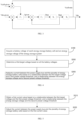
- FIG. 2 is a control principle diagram of a power-source control method according to an embodiment of the present application.
- Vcell is a battery voltage of an energy storage battery cell 110
- Vcell-given is a first preset voltage threshold
- Vcell-max is a first target voltage
- Vbatt_given is a second preset voltage threshold
- Vbatt is an energy storage voltage of the energy storage system 100
- Igiven is a first current value
- Ibatt is a current value between the power supply bus 130 and the energy storage battery cells110
- Duty is a duty cycle value in a first duty cycle control signal.
- the energy storage system 100 includes a first controller and a second controller.
- the first controller may output a first current value based on a difference between the first preset voltage threshold and the battery voltage and a difference between the second preset voltage threshold and the energy storage voltage
- the second controller may output a first duty cycle control signal based on a difference between the first current value and a current flowing through the energy storage system 100.
- the switching transistor Based on the first duty cycle control signal, the switching transistor can be controlled to turn on or off, thereby adjusting the current between the power supply bus 130 and the plurality of energy storage battery cells 110, and further adjusting the battery voltages of the energy storage battery cells 110, such that the energy storage voltage of the energy storage system 100 reaches a specified voltage.
- FIG. 3 is a control diagram of another power-source control method according to an embodiment of the present application.
- Vcell is a battery voltage of an energy storage battery cell 110
- Vcell-given is a third preset voltage threshold
- Vcell-min is a second target voltage
- Vdc_given is a fourth preset voltage threshold
- Vdc is a bus voltage of the power supply bus 130
- Igiven is a second current value
- Ibatt is a current value between the power supply bus 130 and the energy storage battery cells 110
- Duty is a duty cycle value in a second duty cycle control signal.
- the first controller may output a second current value based on a difference between the third preset voltage threshold and the battery voltage and a difference between the fourth preset voltage threshold and the bus voltage
- the second controller may output a second duty cycle control signal based on a difference between the second current value and the current flowing through the power supply bus 130. Therefore, based on the second duty cycle control signal, the switching transistor can be controlled to turn on or off, and thus the current between the power supply bus 130 and the plurality of energy storage battery cells 110 can be adjusted, thereby adjusting the battery voltages of the energy storage battery cells 110, such that the energy storage voltage of the energy storage system 100 reaches a specified voltage, while the bus voltage of the power supply bus 130 can reach a corresponding specified voltage.
- the energy storage system 100 described in the embodiments of the present application is for more clearly explaining the technical schemes of the embodiments of the present application, and does not constitute a limitation on the technical schemes provided by the embodiments of the present application. Those skilled in the art can know that with the evolution of the energy storage system 100 and the emergence of new application scenarios, the technical schemes provided by the embodiments of the present application are also applicable to similar technical problems.
- FIG. 1 does not limit the embodiments of the present application, and there may be more or fewer components than illustrated, or some of the components may be combined, or a different arrangement of the components may be used.
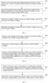
- FIG. 4 is a flowchart of a power-source control method of an energy storage system according to an embodiment of the present application.
- the power-source control method of the energy storage system can be applied to the energy storage system 100 shown in FIG. 1 , and the power-source control method of the energy storage system includes, but is not limited to, the following steps.
- a first target voltage is determined based on all the battery voltages.
- a current between the power supply bus and the plurality of energy storage battery cells is adjusted based on a relationship between the first target voltage and a first preset voltage threshold, and a relationship between the energy storage voltage and a second preset voltage threshold.
- the corresponding battery voltage is obtained by measuring the voltage of each energy storage battery cell, and the energy storage voltage of the entire energy storage system is obtained by measuring the voltage of the energy storage system. Since the respective energy storage battery cells are connected in series to each other, the energy storage voltage can be obtained by calculating the sum of all the battery voltages.
- a first target voltage is determined from all the battery voltages, and the first target voltage can be expressed as a battery voltage of the energy storage battery cell that is prone to overcharging among the current energy storage battery cells.
- a first voltage difference is obtained by comparing the first target voltage with a first preset voltage threshold that is set in advance, where the first preset voltage threshold may be an energy storage upper limit of the energy storage battery cell.
- the first voltage difference indicates the amount of electrical energy that the corresponding energy storage battery cell can currently continue to store.
- a second voltage difference is obtained by comparing the energy storage voltage of the energy storage system with the second preset voltage threshold that is set in advance, where the second preset voltage threshold may be a target charging voltage of the energy storage system, that is, the energy storage voltage is monitored in real time, and the target charging voltage is compared with the current energy storage voltage in real time to obtain the energy storage condition of the current energy storage system, to determine whether the energy storage system needs to continue charging.
- the second voltage difference can indicate the amount of electrical energy that the current energy storage system can continue to store.
- the second voltage difference is 0, it can be considered that the energy storage system has completed energy storage and does not need to continue charging, and the current between the power supply bus and the plurality of energy storage battery cells can be adjusted to 0 to avoid overcharging and damage to the energy storage system.
- the second voltage difference is greater than 0, it can be considered that the energy storage system has not completed energy storage and still needs to continue charging, and as the first voltage difference is small, it can be considered that the current power of the storage battery cell is high and is about to reach its upper limit of energy storage. Therefore, it is necessary to reduce the current flowing through the energy storage system.
- the power entering the energy storage battery cells also decreases accordingly, thereby avoiding overcharging of the energy storage battery cell.
- the first voltage difference is 0 or less than 0, that is, the first target voltage is equal to or higher than the first preset voltage threshold, it is indicated that the current power of the energy storage battery cell has reached its target energy storage value. If the energy storage system continues to charge with the same current condition, the energy storage battery cell may be overcharged and damaged. Therefore, the energy storage system is stopped from charging and storing energy, so that the battery voltage of the energy storage battery cell can be stabilized within a safe threshold range, effectively preventing the overvoltage in the energy storage battery cell.
- the energy storage condition of the energy storage battery cells is determined by comparing the first target voltage with the first preset voltage threshold, and the energy storage condition of the whole energy storage system is determined by comparing the energy storage voltage with the second preset voltage threshold. Based on the individual energy storage conditions of the energy storage battery cells and the overall energy storage situation of the energy storage system, the current between the power supply bus and the plurality of energy storage battery cells can be adjusted, i.e., the current flowing through the energy storage battery cells can be adjusted, thereby allowing for adjustment of both the battery voltages of the energy storage battery cells and the overall energy storage voltage of the system.
- the current through the energy storage battery cell can be regulated in real-time, continuously stabilizing the battery voltages of the energy storage battery cells until the energy storage voltage reaches the second preset voltage threshold. This reduces the occurrence of overvoltage in the energy storage battery cells and enhances the reliability and service life of the energy storage system.
- step S300 includes, but is not limited to, the following steps.
- a first current value is obtained based on a relationship between the first target voltage and the first preset voltage threshold, and a relationship between the energy storage voltage and the second preset voltage threshold.
- the current between the power supply bus and the plurality of energy storage battery cells is adjusted based on the first current value.
- the current energy storage condition of the energy storage battery cells is determined by the difference between the first preset voltage threshold and the first target voltage, thereby determining the first current value.
- the difference between the second preset voltage threshold and the energy storage voltage is large, it is indicated that the current energy storage system has a significant capacity left for further charging, and as the difference between the first preset voltage threshold and the first target voltage is large, it is indicated that, the energy storage battery cells also have a considerable capacity for further charging, and the obtained first current value can be larger, thus the energy storage rate is increased while stabilizing the battery voltages.
- the difference between the second preset voltage threshold and the energy storage voltage is small, it is indicated that the current energy storage system has little capacity left for further charging, and as the difference between the first preset voltage threshold and the first target voltage is small, it is indicated that, the energy storage battery cells also have little capacity left for further charging.
- the current flowing through the energy storage battery cells can be regulated accordingly, which stabilizes the current flowing between the power supply bus and the energy storage battery cells until the energy storage voltage reaches the second preset voltage threshold, and also ensures that the battery voltages remain within a safe threshold range, thereby avoiding overcharging of the energy storage battery cells and enhancing the reliability and service life of the energy storage system.
- step S320 includes, but is not limited to, the following steps.
- a first duty cycle control signal is obtained based on the first current value and a current currently flowing through the energy storage system.
- the switch device is controlled based on the first duty cycle control signal to adjust the current between the power supply bus and the plurality of energy storage battery cells.
- the current that is currently flowing through the energy storage system is measured, and by comparing the difference between the first current value and the current that is currently flowing through the energy storage system, it is determined whether the current that is currently flowing through the energy storage system has reached the first current value.
- the first duty cycle control signal is obtained using the difference between the first current value and the current that is currently flowing through the energy storage system. Since the power supply bus is connected to the plurality of energy storage battery cells through switch devices, the first duty cycle control signal can be used to control the conduction state of the switch devices, which allows for the regulation of the current flowing through the switch devices, thereby stabilizing the battery voltages of the energy storage battery cells, avoiding overcharging, and enhancing the reliability and service life of the energy storage system.
- step S200 includes, but is not limited to, the following steps.
- a battery voltage having the largest voltage value is determined from among all the battery voltages.
- the battery voltage having the largest voltage value is determined as the first target voltage.
- the battery voltage having the largest voltage value is determined from all the battery voltages, which indicates that in the current condition, this energy storage battery cell is the first one prone to reach its upper limit of energy storage, meaning it has the highest probability of overcharging, so that the battery voltage is used as the first target voltage, and the current between the power supply bus and the plurality of energy storage battery cells is adjusted based on the first target voltage, so as to avoid overcharging of the energy storage battery cells before the entire energy storage system is fully charged.
- FIG. 8 is a flowchart of another power-source control method of an energy storage system according to an embodiment of the present application.
- the power-source control method of the energy storage system can be applied to the energy storage system 100 shown in FIG. 1 , and the power-source control method of the energy storage system includes, but is not limited to, the following steps.
- a second target voltage is determined based on all the battery voltages.
- a current between the power supply bus and the plurality of energy storage battery cells is adjusted based on a relationship between the second target voltage and a third preset voltage threshold, and a relationship between the bus voltage and a fourth preset voltage threshold.
- the corresponding battery voltage is obtained by monitoring the voltage of each energy storage battery cell in real time, and the voltage of the power supply bus is monitored in real time to obtain the bus voltage, that is, the actual power supply voltage of the energy storage system.
- the second target voltage is determined from all the battery voltages, and the second target voltage can be expressed as the battery voltage of an energy storage battery cell that is prone to over-discharge among the energy storage battery cells.
- the energy storage condition of the battery cells is determined, indicating whether they can continue to discharge and supply energy, and by comparing the difference between the fourth target voltage and the bus voltage, the current power supply condition of the energy storage system is determined.
- the fourth preset voltage threshold may be the rated power supply voltage of the energy storage system, that is, the voltage required by a power consumption device.
- the difference between the rated power supply voltage and the actual power supply voltage is used to determine whether the actual power supply voltage of the energy storage system reaches the rated power supply voltage, ensuring stable voltage delivery to the power consumption device.
- the difference between the fourth target voltage and the bus voltage is 0, it is indicated that the current actual power supply voltage reaches the rated power supply voltage, and the bus voltage can be stabilized by maintaining the current between the current power supply bus and the plurality of energy storage battery cells, and thus a stable voltage can be provided to the power consumption device.
- the third preset voltage threshold may be obtained based on the battery characteristics of the energy storage battery cells, for example, a lower limit value of the discharge voltage of the energy storage battery cells.
- the battery voltage When the battery voltage is lower than the third preset voltage threshold, it can be considered that the current battery voltage is low, that is, the power of the energy storage battery power supply is insufficient. If the energy storage system continues to discharge by the current state, the energy storage battery cell will be over-discharged before the energy storage system ends discharging, and therefore, the discharge and energy supply of the energy storage system should be stopped.
- the dischargeable energy supply condition of the energy storage battery cell is determined.
- the overall energy supply condition of the energy storage system is determined by comparing the bus voltage and the fourth preset voltage threshold. Combining the dischargeable energy supply condition of the energy storage battery cells and the overall energy supply condition of the energy storage system allows for adjustments to be made to the current between the power supply bus and the multiple energy storage battery cells, which can modulate the current flowing through the energy storage battery cells, thereby regulating both the battery voltages of the energy storage battery cells and the bus voltage of the power supply bus, reducing the occurrence of over-discharging in the energy storage battery cells and regulating and hence stabilizing the bus voltage of the power supply bus to the fourth preset voltage threshold, which enhances the reliability and service life of the energy storage system.
- the overall energy storage voltage of the energy storage system may also be monitored in real time to determine whether the remaining electrical energy of the energy storage system, i.e., the electrical energy in the energy storage system, is sufficient to continue to supply power.
- the energy storage voltage is lower than a specified voltage, it can be considered that the current remaining power of the energy storage system cannot continue to supply power, so the current between the power supply bus and the energy storage battery cell can be adjusted to 0, that is, the power supply from the energy storage system is stopped.
- step S600 includes, but is not limited to, the following steps.
- a second current value is obtained based on a relationship between the second target voltage and the third preset voltage threshold, and a relationship between the bus voltage and the fourth preset voltage threshold.
- the current between the power supply bus and the plurality of energy storage battery cells is adjusted based on the second current value.
- the difference between the fourth preset voltage threshold and the bus voltage is large, it is indicated that the current actual power supply voltage is far from the rated power supply voltage, and as the difference between the third preset voltage threshold and the second target voltage is large, it is indicated that the current energy storage battery cells have a considerable capacity for further discharging and energy supply, and the second current value is larger.
- the difference between the fourth preset voltage threshold and the bus voltage is small, it is indicated that the current actual supply voltage is close to the rated supply voltage, and as the difference between the third preset voltage threshold and the second target voltage is small, it is indicated that the current energy available for discharge from the energy storage battery cells is limited.
- the obtained second current value is small, which, while ensuring that the bus voltage remains stable at the rated supply voltage, limits the current flowing out of the energy storage system, reduces the energy flowing out of the energy storage battery cells, and stabilizes the battery voltages of the energy storage battery cells within a safe threshold range.
- the second target voltage is lower than the third preset voltage threshold, it can be considered that the energy storage battery cells are over-discharged, and it is necessary to stop the discharge and energy supply of the energy storage system to avoid damage to the energy storage system.
- the current flowing out of the energy storage battery cells can be regulated accordingly, which stabilizes the bus voltage at the fourth preset voltage threshold and also ensures that the battery voltages remain within a safe threshold range, thereby avoiding over-discharging of the energy storage battery cells and enhancing the reliability and service life of the energy storage system.
- step S620 includes, but is not limited to, the following steps.
- s second duty cycle control signal is obtained based on the second current value and the current currently flowing through the power supply bus.
- the switch device is controlled based on the second duty cycle control signal to adjust the current between the power supply bus and the plurality of energy storage battery cells.
- the current that is currently flowing through the power supply bus is measured, and by comparing the difference between the second current value and the current that is currently flowing through the power supply bus, it is determined whether the current that is currently flowing through the power supply bus has reached the second current value.
- the second duty cycle control signal is obtained by using the difference between the second current value and the current that is currently flowing through the power supply bus.
- the conduction state of the switch device is controlled by the second duty ratio control signal, and the current flowing through the switch device can be adjusted, that is, the current between the power supply bus and the plurality of energy storage battery cells can be adjusted to stabilize the bus voltage by the fourth preset voltage threshold, and the battery voltages of the energy storage battery cells can be stabilized within a safe threshold range, so as to avoid the over-discharge of the energy storage battery cells and improve the reliability and service life of the energy storage system.
- step S500 includes, but is not limited to, the following steps.
- the battery voltage having the smallest voltage value is determined as the second target voltage.
- the battery voltage having the smallest voltage value is determined from all the battery voltages, which indicates that in the current condition, this energy storage battery cell is the first one to reach its lower limit of energy supply, meaning it has the highest probability of over-discharging, so that its battery voltage is used as the second target voltage, and the current between the power supply bus and the plurality of energy storage battery cells is adjusted based on the second target voltage, so as to avoid over-discharging of the energy storage battery cells before the entire energy storage system is fully discharged.
- FIG. 12 is a schematic diagram of an operation control apparatus 1200 according to an embodiment of a third aspect of the present application.
- the operation control apparatus 1200 includes: a memory 1210, a processor 1220, and a computer program stored in the memory 1210 and executable by the processor 1220, where the processor 1220, when executing the computer program, implements the power-source control method of the energy storage system in the above embodiments.
- the memory 1210 may be configured to store a non-transitory software program and a non-transitory computer-executable program, for example, the power-source control method of the energy storage system described in the above embodiments of the present application.
- the processor 1220 implements the power-source control method of the energy storage system in the above embodiments of the present application by executing the non-transitory software program and instructions stored in the memory 1210.
- the memory 1210 may include a program storage area and a data storage area, where the program storage area may store an operating system and application program(s) required by at least one function, and the data storage area may store data required for performing the power-source control method of the energy storage system in the above-described embodiments.
- the memory 1210 may include a high-speed random access memory 1210 and a non-transitory memory 1210, for example, at least one of a magnetic disk storage device, a flash memory device, or another non-transitory solid-state storage device.
- the memory 1210 optionally includes memories 1210 located remotely with respect to the processor 1220, and these remote memories 1210 may be connected to the terminal device through a network. Examples of the above-mentioned network include, but are not limited to, the Internet, an intranet, a local area network, a mobile communication network, or a combination thereof.
- a non-transitory software program and instructions required to implement the power-source control method of the energy storage system of the above embodiments are stored in the memory, and when executed by one or more processors, enable the one or more processors to perform the power-source control method of the energy storage system of the above embodiments, for example, to perform the above-described method steps S100 to S300 in FIG. 4 , method steps S310 to S320 in FIG. 5 , method steps S321 to S322 in FIG. 6 , method steps S210 to S220 in FIG. 7 , method steps S400 to S600 in FIG. 8 , method steps S610 to S620 in FIG. 9 , method steps S621 to S622 in FIG. 10 , or method steps S510 to S520 in FIG. 11 .
- An embodiment of the fourth aspect of the present application provides an energy storage system including the operation control apparatus 1200 according to the embodiment of the third aspect. Therefore, based on the relationship between the first target voltage of the battery voltages and the first preset voltage threshold, and the relationship between the energy storage voltage of the energy storage system and the second preset voltage threshold, or based on the relationship between the second target voltage of the battery voltages and the third preset voltage threshold, and the difference between the bus voltage of the power supply bus and the fourth preset voltage threshold, the current between the power supply bus and the plurality of energy storage battery cells is regulated in real time, so as to accordingly adjust the energy storage voltage or the bus voltage to reach the preset voltage threshold, while preventing the battery voltage from becoming too high or too low, thereby avoiding overcharging or over-discharging of the energy storage battery cells and improving the reliability and service life of the energy storage system.
- An embodiment of the fifth aspect of the present application provides a computer-readable storage medium storing computer-executable instructions, which may be configured to enable a computer to perform the power-source control method of the energy storage system according to the embodiment of the second aspect described above, for example, to perform the above-described method steps S100 to S300 in FIG. 4 , method steps S310 to S320 in FIG. 5 , method steps S321 to S322 in FIG. 6 , method steps S210 to S220 in FIG. 7 , method steps S400 to S600 in FIG. 8 , method steps S610 to S620 in FIG. 9 , method steps S621 to S622 in FIG. 10 , or method steps S510 to S520 in FIG. 11 .
- computer-readable storage medium includes volatile and nonvolatile, removable and non-removable media implemented in any method or technique for storage of information, such as computer-readable instructions, data struFctures, program modules or other data.
- a computer-readable storage medium includes but is not limited to RAM, ROM, EEPROM, flash memory or other memory technologies, CD-ROM, digital versatile disk (DVD) or other optical disk storage, cassettes, magnetic tapes, magnetic disk storage or other magnetic storage apparatuses, or any other medium that can be configured to store desired information and can be accessed by a computer.
- communication media typically contain computer-readable instructions, data structures, program modules or other data in a modulated data signal such as a carrier wave or other transmission mechanism, and may include any information transmission media.
Landscapes
- Engineering & Computer Science (AREA)
- Power Engineering (AREA)
- Charge And Discharge Circuits For Batteries Or The Like (AREA)
- Secondary Cells (AREA)
Applications Claiming Priority (2)
| Application Number | Priority Date | Filing Date | Title |
|---|---|---|---|
| CN202211052168.8A CN117674332A (zh) | 2022-08-31 | 2022-08-31 | 储能系统及其电源控制方法、装置、存储介质 |
| PCT/CN2023/109145 WO2024045956A1 (fr) | 2022-08-31 | 2023-07-25 | Système de stockage d'énergie et procédé de commande de source d'alimentation et appareil associé, et support de stockage |
Publications (2)
| Publication Number | Publication Date |
|---|---|
| EP4576489A1 true EP4576489A1 (fr) | 2025-06-25 |
| EP4576489A4 EP4576489A4 (fr) | 2025-12-10 |
Family
ID=90072043
Family Applications (1)
| Application Number | Title | Priority Date | Filing Date |
|---|---|---|---|
| EP23858992.3A Pending EP4576489A4 (fr) | 2022-08-31 | 2023-07-25 | Système de stockage d'énergie et procédé de commande de source d'alimentation et appareil associé, et support de stockage |
Country Status (4)
| Country | Link |
|---|---|
| EP (1) | EP4576489A4 (fr) |
| CN (1) | CN117674332A (fr) |
| AU (1) | AU2023334958A1 (fr) |
| WO (1) | WO2024045956A1 (fr) |
Families Citing this family (1)
| Publication number | Priority date | Publication date | Assignee | Title |
|---|---|---|---|---|
| CN118783507A (zh) * | 2024-09-11 | 2024-10-15 | 武汉大学 | 基于抽水蓄能与电池储能联合系统的有功控制方法和装置 |
Family Cites Families (7)
| Publication number | Priority date | Publication date | Assignee | Title |
|---|---|---|---|---|
| JP3296385B2 (ja) * | 1994-07-06 | 2002-06-24 | ミツミ電機株式会社 | 電池の電圧検出回路 |
| CN105529766B (zh) * | 2015-12-07 | 2019-05-28 | 上海空间电源研究所 | 一种应用于s4r型电路的防过充装置 |
| CN108282007B (zh) * | 2018-02-12 | 2020-12-25 | 中航锂电技术研究院有限公司 | 通信电池模块充电限流策略 |
| CN109347154B (zh) * | 2018-09-19 | 2022-06-17 | 莱克电气股份有限公司 | 锂电池充放电驱动保护系统 |
| KR102594315B1 (ko) * | 2019-03-05 | 2023-10-27 | 현대자동차주식회사 | 차량 및 그 제어 방법 |
| CN112636406B (zh) * | 2020-11-26 | 2023-04-07 | 西安讯服通科技有限公司 | 一种用于不间断电源的电池管理方法和装置 |
| CN114844176A (zh) * | 2022-06-07 | 2022-08-02 | 青岛能蜂电气有限公司 | 电池充放电功率控制方法、装置和电子设备 |
-
2022
- 2022-08-31 CN CN202211052168.8A patent/CN117674332A/zh active Pending
-
2023
- 2023-07-25 AU AU2023334958A patent/AU2023334958A1/en active Pending
- 2023-07-25 WO PCT/CN2023/109145 patent/WO2024045956A1/fr not_active Ceased
- 2023-07-25 EP EP23858992.3A patent/EP4576489A4/fr active Pending
Also Published As
| Publication number | Publication date |
|---|---|
| WO2024045956A1 (fr) | 2024-03-07 |
| AU2023334958A1 (en) | 2025-03-13 |
| EP4576489A4 (fr) | 2025-12-10 |
| CN117674332A (zh) | 2024-03-08 |
Similar Documents
| Publication | Publication Date | Title |
|---|---|---|
| KR102392376B1 (ko) | 배터리 시스템 | |
| US9906052B2 (en) | Power supply device | |
| US20130187465A1 (en) | Power management system | |
| CN113746151B (zh) | 一种电池充电方法、电子装置、存储介质及程序产品 | |
| KR102342202B1 (ko) | 배터리 장치 및 그 제어 방법 | |
| KR102534561B1 (ko) | 충방전 장치, 배터리 충방전 방법 및 충방전 시스템 | |
| US20240092211A1 (en) | Method and device for charging secondary battery, computer storage medium, and electronic equipment | |
| JP2024502840A (ja) | 動力電池の充電の方法及び電池管理システム | |
| US11063458B1 (en) | Systems and methods for dynamic pulse charging | |
| EP4290648A1 (fr) | Procédé de commande de charge et appareil de commande de charge pour système de batterie | |
| US20240178686A1 (en) | Control method and control device for battery system and battery system | |
| CN117955140B (zh) | 功率分配方法、装置、储能电站及存储介质 | |
| EP4576489A1 (fr) | Système de stockage d'énergie et procédé de commande de source d'alimentation et appareil associé, et support de stockage | |
| US20220060030A1 (en) | Power Feeding Control Device, Power Feeding System, and Power Feeding Method | |
| JP2012182857A (ja) | 直流電源装置 | |
| KR20150050215A (ko) | 배터리 팩 관리 장치 및 방법 | |
| CN112928798B (zh) | 储能设备的电量控制方法、装置和储能设备 | |
| CN117674340A (zh) | 储能系统及其电源控制方法、装置、存储介质 | |
| US12314022B2 (en) | Power management device, upper power management device, and power management method | |
| CN112913107A (zh) | 蓄电系统以及充电控制方法 | |
| EP4432511A1 (fr) | Procédé et système de commande de charge, et dispositif terminal, chargeur et support de stockage | |
| US20240396361A1 (en) | DC Power Plant and Method of Recharging the Same | |
| TWI901111B (zh) | 充電裝置 | |
| US20250030254A1 (en) | Apparatus and method for energy maximization in a secondary battery system | |
| US20240146085A1 (en) | Battery charging method and system |
Legal Events
| Date | Code | Title | Description |
|---|---|---|---|
| STAA | Information on the status of an ep patent application or granted ep patent |
Free format text: STATUS: THE INTERNATIONAL PUBLICATION HAS BEEN MADE |
|
| PUAI | Public reference made under article 153(3) epc to a published international application that has entered the european phase |
Free format text: ORIGINAL CODE: 0009012 |
|
| STAA | Information on the status of an ep patent application or granted ep patent |
Free format text: STATUS: REQUEST FOR EXAMINATION WAS MADE |
|
| 17P | Request for examination filed |
Effective date: 20250317 |
|
| AK | Designated contracting states |
Kind code of ref document: A1 Designated state(s): AL AT BE BG CH CY CZ DE DK EE ES FI FR GB GR HR HU IE IS IT LI LT LU LV MC ME MK MT NL NO PL PT RO RS SE SI SK SM TR |
|
| A4 | Supplementary search report drawn up and despatched |
Effective date: 20251107 |
|
| DAV | Request for validation of the european patent (deleted) | ||
| DAX | Request for extension of the european patent (deleted) | ||
| RIC1 | Information provided on ipc code assigned before grant |
Ipc: H02J 7/00 20060101AFI20251103BHEP |