EP4576503A1 - Rotor für elektrische drehmaschine - Google Patents
Rotor für elektrische drehmaschine Download PDFInfo
- Publication number
- EP4576503A1 EP4576503A1 EP23885700.7A EP23885700A EP4576503A1 EP 4576503 A1 EP4576503 A1 EP 4576503A1 EP 23885700 A EP23885700 A EP 23885700A EP 4576503 A1 EP4576503 A1 EP 4576503A1
- Authority
- EP
- European Patent Office
- Prior art keywords
- magnet
- rotor
- steel sheets
- rotor core
- outer circumferential
- Prior art date
- Legal status (The legal status is an assumption and is not a legal conclusion. Google has not performed a legal analysis and makes no representation as to the accuracy of the status listed.)
- Pending
Links
Images


Classifications
-
- H—ELECTRICITY
- H02—GENERATION; CONVERSION OR DISTRIBUTION OF ELECTRIC POWER
- H02K—DYNAMO-ELECTRIC MACHINES
- H02K1/00—Details of the magnetic circuit
- H02K1/06—Details of the magnetic circuit characterised by the shape, form or construction
- H02K1/22—Rotating parts of the magnetic circuit
- H02K1/27—Rotor cores with permanent magnets
- H02K1/2706—Inner rotors
- H02K1/272—Inner rotors the magnetisation axis of the magnets being perpendicular to the rotor axis
- H02K1/274—Inner rotors the magnetisation axis of the magnets being perpendicular to the rotor axis the rotor consisting of two or more circumferentially positioned magnets
- H02K1/2753—Inner rotors the magnetisation axis of the magnets being perpendicular to the rotor axis the rotor consisting of two or more circumferentially positioned magnets the rotor consisting of magnets or groups of magnets arranged with alternating polarity
- H02K1/276—Magnets embedded in the magnetic core, e.g. interior permanent magnets [IPM]
- H02K1/2766—Magnets embedded in the magnetic core, e.g. interior permanent magnets [IPM] having a flux concentration effect
-
- H—ELECTRICITY
- H02—GENERATION; CONVERSION OR DISTRIBUTION OF ELECTRIC POWER
- H02K—DYNAMO-ELECTRIC MACHINES
- H02K15/00—Processes or apparatus specially adapted for manufacturing, assembling, maintaining or repairing of dynamo-electric machines
- H02K15/02—Processes or apparatus specially adapted for manufacturing, assembling, maintaining or repairing of dynamo-electric machines of stator or rotor bodies
- H02K15/03—Processes or apparatus specially adapted for manufacturing, assembling, maintaining or repairing of dynamo-electric machines of stator or rotor bodies having permanent magnets
- H02K15/035—Processes or apparatus specially adapted for manufacturing, assembling, maintaining or repairing of dynamo-electric machines of stator or rotor bodies having permanent magnets on the rotor
Definitions
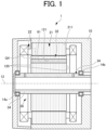
- the present disclosure relates to a rotor for a rotary electric machine.
- Patent Literature 1 JP 2020-114039 A
- the repulsive force generated at an axial end acts in a direction of peeling off the steel sheet at the axial end outward in the axial direction. Therefore, in the rotor core in the form of the laminate of a plurality of steel sheets, it is useful to set a welded portion against such a repulsive force.
- the welded portion is set near an outer circumferential bridge on the outer circumferential surface of the rotor core, there is a problem that stress in the outer circumferential bridge tends to increase due to thermal contraction in the welded portion.
- the present disclosure provides a welded portion against a repulsive force in a manner that the influence of stress caused by welding can be reduced.
- a rotor for a rotary electric machine including a rotor core in a form of a laminate of a plurality of steel sheets, the rotor core having a magnet hole in an axial direction, and
- the longitudinal direction of the permanent magnet 61 corresponds to a direction perpendicular to the side surfaces 610 on both sides of the permanent magnet 61
- the width direction of the permanent magnet 61 is a direction perpendicular to the longitudinal direction of the permanent magnet 61 as viewed in the axial direction.
- an edge portion 1211 is an edge portion facing the outer circumferential-side surface 6101 of the permanent magnet 61 in the longitudinal direction of the permanent magnet 61.
- the edge portion 1211 is located between the radially outer edge portion 1213 and the radially inner edge portion 1214 and bounds the outer circumferential bridge 41.
- An edge portion 1212 is an edge portion facing the d-axis side surface 6102 of the permanent magnet 61 in the longitudinal direction of the permanent magnet 61.
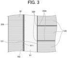
- the present manufacturing method includes an inserting step of inserting the permanent magnet 61 to which a material (adhesive) related to the adhesive layer 162 is applied into the magnet hole 121 of the rotor core 32.
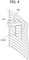
- the insertion step involves elastically deforming the protrusion 328.
- a projection length L10 of the protrusion 328 in a form before elastic deformation (form extending straight in the radial direction) illustrated in FIG. 4 may be appropriately set.
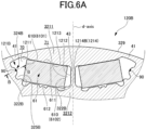
- FIG. 6A is an explanatory diagram of the magnet hole forming portion 121B of the steel sheet 120B including the welded portion 90, and is a cross-sectional view illustrating a configuration (detailed configuration of a range Q1 in FIG. 2 ) at one magnetic pole of the steel sheet 120B together with the permanent magnet 61.
- FIG. 6A corresponds to a cross-sectional view through the thickness center of the steel sheet 120B taken along a plane perpendicular to the axial direction.
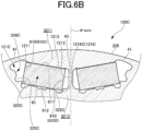
- FIG. 6B is a cross-sectional view illustrating a configuration (detailed configuration of the range Q1 in FIG.
- FIG. 6B corresponds to a cross-sectional view through the thickness center of the steel sheet 120C taken along a plane perpendicular to the axial direction.
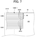
- FIG. 7 illustrates a part of a cross-section of the rotor core 32 taken along line B-B in FIG. 6A . Note that, in FIG. 6A and the like, illustration of the adhesive layer 162 described above with reference to FIG. 3 is omitted.
- the steel sheet 120B has a protrusion 322B along the width direction of the permanent magnet 61 at a radially inner edge portion 1214B of the magnet hole forming portion 121B.
- the protrusions 322B form a pair and face the side surfaces 610 on both sides of the permanent magnet 61 in the longitudinal direction of the permanent magnet 61. That is, among the paired protrusions 322B, the protrusion 322B away from the d-axis faces the outer circumferential-side surface 6101 of the permanent magnet 61, and the protrusion 322B near the d-axis faces the d-axis side surface 6102 of the permanent magnet 61.
- the paired protrusions 322B, 322C function as a guide when the permanent magnet 61 is inserted into the magnet hole 121, and are hereinafter also referred to as "paired guide protrusions 322B, 322C".
- the paired guide protrusions 322B, 322C are formed on the plurality of steel sheets to form two projecting sections extending in the axial direction, and the two projecting sections bound the ends of the insertion space of the permanent magnet 61 (ends in the longitudinal direction of the permanent magnet 61). Note that, in the modification, some of the plurality of steel sheets 120 forming one rotor core 32 do not need to have protrusions corresponding to the guide protrusions 322B and 322C.
- the steel sheet 120B has a projection 324B along the width direction of the permanent magnet 61 at the radially inner edge portion 1214B of the magnet hole forming portion 121B.
- the projection 324B is disposed closer to the radially outer side (side closer to the outer circumferential bridge 41) than the paired guide protrusions 322B. Note that the projection 324B extends to a flux barrier (cavity) 70 adjacent to the outer circumferential bridge 41 in the magnet hole 121.
- the steel sheet 120B preferably has a recess 325B adjacent to the projection 324B when viewed in the axial direction, as illustrated in FIG. 6A .
- the recess 325B is recessed radially inward, and is adjacent to the projection 324B from the d-axis side.
- the uneven shape formed by the projection 324B and the recess 325B is preferably continuous with a relatively large corner R interposed therebetween. As a result, as will be described later, it is possible to reduce the influence of stress that may be generated when the welded portion 90 is provided on the projection 324B.
- the recess 325B may be adjacent to the projection 324B from the outer circumferential bridge 41 side, or may be formed on both sides of the projection 324B.
- Two or more steel sheets 120B are continuously laminated in an axially adjacent manner, and the welded portion 90 is provided on the projection 324B. That is, the steel sheets 120B laminated in an axially adjacent manner are joined to each other by welding the projections 324B to each other in the axial direction. Any welding method is possible, but welding using a laser is suitable. Any laser can be used, but an infrared laser, a green laser, or the like may be used.
- the projection 324B extends to the flux barrier 70 in the magnet hole 121, laser irradiation for forming the welded portion 90 is easily performed using the cavity related to the flux barrier.
- the welded portion 90 can be easily formed at a portion of the rotor core 32 other than the outer circumferential surface 329 using the flux barrier 70.
- the flux barrier 70 adjacent to the outer circumferential bridge 41 and a flux barrier 71 adjacent to the d-axis are formed on both sides of the permanent magnet 61 in the magnet hole 121.
- the portion extending to the flux barrier 70 is longer than the portion extending to the flux barrier 71. Therefore, according to the present embodiment, the welded portion 90 can be formed using the relatively long radially inner edge portion 1214 of the flux barrier 70.
- the space for forming the welded portion 90 is relatively largely restricted, but the welded portion 90 can be appropriately formed by using the flux barrier 70.
- the steel sheet 120C may have a projection 324C along the width direction of the permanent magnet 61 at a radially inner edge portion 1214C of the magnet hole forming portion 121C.
- the projection 324C may be the same as the projection 324B of the steel sheet 120B described above, and these projections may have the same form so as to overlap each other when viewed in the axial direction.
- the steel sheet 120C may have a recess 325C adjacent to both sides of the projection 324C.
- the steel sheet 120C is different from the steel sheet 120B described above in that the welded portion 90 is not provided. That is, although two or more steel sheets 120C can be continuously stacked in an axially adjacent manner, the projections 324C are not welded to each other. Note that the steel sheet 120C can have substantially the same configuration as the steel sheet 120B except that the welded portion 90 is not provided. In this case, it is possible to commonize a punching die for manufacturing the steel sheet 120B and the steel sheet 120C.
- the steel sheets 120B may be all the steel sheets 120 forming one rotor core 32 (that is, the steel sheet 120C does not need to be present), but are preferably part of a plurality of steel sheets 120 forming one rotor core 32. That is, the steel sheets 120B including the welded portion 90 occupy only a part of the plurality of steel sheets 120 forming the rotor core 32.
- the welded portion 90 against the repulsive force can be provided on the steel sheet 120B forming the axial end face 2110 of the rotor core 32.
- the permanent magnet 61 is firmly bonded to the rotor core 32 via the adhesive layer 162. Therefore, according to the present embodiment, the end plate can be eliminated, and in this case, the number of components can be reduced and the cost can also be reduced.
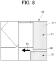
- FIG. 9 is an explanatory diagram of welded portions 90' and 90" in a steel sheet 120B' according to a comparative example, and is a cross-sectional view illustrating a configuration of one magnetic pole (detailed configuration of the range Q1 in FIG. 2 ).
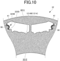
- FIG. 10 is a contour diagram illustrating a stress analysis result in the rotor core 32 according to the present embodiment.
- the welded portions 90' and 90" are respectively provided on projections 324' and 324" with the same form as the projection 324B according to the present embodiment. However, since the welded portion 90" is provided near the outer circumferential bridge 41, there is a problem that stress in the outer circumferential bridge 41 is likely to increase due to thermal contraction at the welded portion 90".
- the welded portion 90' is disposed away from the outer circumferential bridge 41, the stress in the outer circumferential bridge 41 due to the thermal contraction at the welded portion 90' can be reduced compared to the case of the welded portion 90".
- the welded portion 90' is disposed to affect a magnetic path in a first portion 3211', there is a problem that the torque characteristics of the rotary electric machine deteriorate.
- the welded portion 90 is provided on the second portion 3212 side (radially inner edge portion 1214B) of the rotor core 32, the stress in the outer circumferential bridge 41 due to the thermal contraction at the welded portion 90 can be reduced as compared with the case of the welded portion 90".
- FIG. 10 illustrates an analysis result showing that a portion where the stress is relatively high does not extend to the outer circumferential bridge 41 and falls within the periphery of the projection 324B.
- stress concentration near the root of the projection 324B can be alleviated, and the influence of stress on the magnetic path of a q-axis magnetic flux in the second portion 3212 can be reduced.
- the welded portion 90 is provided on the second portion 3212 side (radially inner edge portion 1214B) of the rotor core 32, unlike the case of the welded portion 90', the torque characteristics of the rotary electric machine are not deteriorated.
- the projection 324B including the welded portion 90 has a form of projecting radially outward, the projection 324B does not reduce the magnetic path width of the q-axis magnetic flux in the second portion 3212.
- the present embodiment it is possible to provide the welded portion 90 against the repulsive force so as to be capable of reducing the influence of the stress caused by welding.
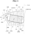
- the radially inner edge portion 1214 of the magnet hole 121 has, in addition to a magnet facing portion 12142 facing the inner surface 612 of the permanent magnet 61, an end 12140 facing the outer circumferential-side surface 6101 of the permanent magnet 61 in a direction perpendicular to the outer circumferential-side surface 6101.
- FIG. 11 which is an enlarged view of a part of FIG. 6A , illustrates a range R11 of the end 12140 of the radially inner edge portion 1214 in the magnet hole 121. Note that the radially outer side of the end 12140 terminates at the outer circumferential bridge 41, and the radially inner side terminates at (continues) the magnet facing portion 12142.
- the welded portion 90 is disposed at the end 121 of the radially inner edge portion 1214.
- the welded portion 90 is disposed at a portion other than the end 121 of the radially inner edge portion 1214 (that is, the magnet facing portion 12142).
- the end 121 of the radially inner edge portion 1214 is farther from the main path of the magnetic flux (the main portion of the magnetic path of the q-axis magnetic flux in the second portion 3212) than the portion other than the end 121.
- the welded portion 90 can be disposed outside the main path of the magnetic flux.
- the plurality of steel sheets 120 forming one rotor core 32 may include the plurality of steel sheets 120B in such a manner that at least one steel sheet 120B corresponds to each permanent magnet 61, preferably two steel sheets 120B correspond to each permanent magnet 61.
- Such a configuration is suitable in a case where the rotor core 32 is formed by rolling a plurality of laminate blocks.
- FIG. 12 is an explanatory diagram of a rotor core 32A formed by rolling a plurality of laminate blocks.
- the rotor core 32A includes four laminate blocks 325(1) to 325(4).
- Each of the laminate blocks 325(1) to 325(4) includes each of the permanent magnets 61 in a manner separated from each other.
- two or more steel sheets 120B continuously laminated in an axially adjacent manner form a portion including the axial end face of the upper laminate block 325(1) and a portion including the axial end face of the lower laminate block 325(4) among the plurality of laminate blocks 325(1) to 325(4).
- the rotor core 32A formed by rolling the plurality of laminate blocks 325(1) to 325(4) can have a symmetrical configuration in the axial direction as a whole while combining the laminate blocks 325(1) to 325(4). That is, the rotor core 32A can implement a symmetrical configuration with respect to a plane passing through the center of the rotor core 32A in the axial direction and perpendicular to the axial direction.
- the paired guide protrusions 322B, 322C are provided, but one or both of the paired guide protrusions 322B, 322C may be omitted.
- the welded portion 90 is provided on the projection 324B, but in the modification, the welded portion may be provided on the recess 325B or another portion in addition thereto or instead thereof.
- the flux barriers 70 and 71 are hollow, but may be filled with resin or the like.
- Rotor Rotary for a rotary electric machine
- 32, 32A Rotor core
- 3211 First portion (Radially outer core portion)
- 3212 Second portion (Radially inner core portion)
- 329 Outer circumferential surface
- 2110 Axial end face
- 121 Magnet hole
- 322B Guide protrusion (Protrusion)
- 61 Permanent magnet (Magnet)
- 120 Steel sheet
- 1211 Edge portion (Third edge portion)
- 1213 Radially outer edge portion (Second edge portion)
- 1214 Radially inner edge portion (First edge portion)
- 324B Projection
- 325B Recess
- 41 Outer circumferential bridge
- 70 Flux barrier
- 90 Welded portion
Landscapes
- Engineering & Computer Science (AREA)
- Power Engineering (AREA)
- Manufacturing & Machinery (AREA)
- Permanent Field Magnets Of Synchronous Machinery (AREA)
- Iron Core Of Rotating Electric Machines (AREA)
Applications Claiming Priority (2)
| Application Number | Priority Date | Filing Date | Title |
|---|---|---|---|
| JP2022174078 | 2022-10-31 | ||
| PCT/JP2023/039032 WO2024095945A1 (ja) | 2022-10-31 | 2023-10-30 | 回転電機用ロータ |
Publications (2)
| Publication Number | Publication Date |
|---|---|
| EP4576503A1 true EP4576503A1 (de) | 2025-06-25 |
| EP4576503A4 EP4576503A4 (de) | 2025-10-01 |
Family
ID=90930527
Family Applications (1)
| Application Number | Title | Priority Date | Filing Date |
|---|---|---|---|
| EP23885700.7A Pending EP4576503A4 (de) | 2022-10-31 | 2023-10-30 | Rotor für elektrische drehmaschine |
Country Status (4)
| Country | Link |
|---|---|
| EP (1) | EP4576503A4 (de) |
| JP (1) | JPWO2024095945A1 (de) |
| CN (1) | CN120113126A (de) |
| WO (1) | WO2024095945A1 (de) |
Family Cites Families (5)
| Publication number | Priority date | Publication date | Assignee | Title |
|---|---|---|---|---|
| EP3091639B1 (de) * | 2010-06-14 | 2018-09-05 | Toyota Jidosha Kabushiki Kaisha | Rotorkern für rotierende elektrische maschine und herstellungsverfahren dafür |
| DE102014209415B4 (de) * | 2014-05-19 | 2024-12-19 | Robert Bosch Gmbh | Blechpaket für eine elektrische Maschine |
| DE112017004437T5 (de) * | 2016-12-26 | 2019-06-19 | Aisin Aw Co., Ltd. | Rotorkernherstellungsverfahren und rotorkern |
| JP7310141B2 (ja) | 2019-01-08 | 2023-07-19 | トヨタ紡織株式会社 | 回転電機のロータ |
| JP2021112074A (ja) * | 2020-01-14 | 2021-08-02 | 本田技研工業株式会社 | ロータ、回転電機およびロータの製造方法 |
-
2023
- 2023-10-30 JP JP2024554491A patent/JPWO2024095945A1/ja active Pending
- 2023-10-30 WO PCT/JP2023/039032 patent/WO2024095945A1/ja not_active Ceased
- 2023-10-30 CN CN202380074529.5A patent/CN120113126A/zh active Pending
- 2023-10-30 EP EP23885700.7A patent/EP4576503A4/de active Pending
Also Published As
| Publication number | Publication date |
|---|---|
| CN120113126A (zh) | 2025-06-06 |
| JPWO2024095945A1 (de) | 2024-05-10 |
| WO2024095945A1 (ja) | 2024-05-10 |
| EP4576503A4 (de) | 2025-10-01 |
Similar Documents
| Publication | Publication Date | Title |
|---|---|---|
| EP2026448B1 (de) | Eisenkern des aufgeteilten typs und verfahren zu seiner herstellung und statoreisenkern | |
| JP6305651B1 (ja) | 永久磁石式同期機および永久磁石式同期機の固定子の製造方法 | |
| JP6900903B2 (ja) | モータおよびモータの製造方法 | |
| CN101800461B (zh) | 直线电动机 | |
| US7893590B2 (en) | Stator having high assembly | |
| CN109690910B (zh) | 旋转电机 | |
| JP2002034187A (ja) | 磁石埋込型回転子 | |
| US11095173B2 (en) | Stator for rotating electric machine, and rotating electric machine | |
| JPH0767272A (ja) | 同期機のステータ構造,その製造方法並びにティース片 | |
| JP5235912B2 (ja) | リラクタンスモータ | |
| KR20170066868A (ko) | 자석 압입형 모터 회전자 | |
| JP3439673B2 (ja) | 積層鉄心 | |
| EP4576503A1 (de) | Rotor für elektrische drehmaschine | |
| JP3615014B2 (ja) | 磁石回転子及びその製造方法 | |
| JP2000333390A (ja) | 永久磁石電動機 | |
| JP3940207B2 (ja) | シンクロナスリラクタンスモータ及びその製造方法 | |
| JP4295691B2 (ja) | 回転電機の電機子 | |
| JPH10112965A (ja) | リラクタンスモータのロータコアとその製造方法 | |
| JPH09285087A (ja) | リラクタンス同期モータ用ロータおよびその製造方法 | |
| WO2021024517A1 (ja) | 回転電機の回転子、回転電機、回転電機の回転子の製造方法、および回転電機の製造方法 | |
| JP2024065254A (ja) | 回転電機用ロータ | |
| JP3987000B2 (ja) | 回転電機の電機子 | |
| CN121055621A (zh) | 定子铁芯叠和定子铁芯 | |
| JP2024173738A (ja) | 回転子 | |
| WO2024195827A1 (ja) | リラクタンスモータのためのロータ、及びリラクタンスモータ |
Legal Events
| Date | Code | Title | Description |
|---|---|---|---|
| STAA | Information on the status of an ep patent application or granted ep patent |
Free format text: STATUS: THE INTERNATIONAL PUBLICATION HAS BEEN MADE |
|
| PUAI | Public reference made under article 153(3) epc to a published international application that has entered the european phase |
Free format text: ORIGINAL CODE: 0009012 |
|
| STAA | Information on the status of an ep patent application or granted ep patent |
Free format text: STATUS: REQUEST FOR EXAMINATION WAS MADE |
|
| 17P | Request for examination filed |
Effective date: 20250318 |
|
| AK | Designated contracting states |
Kind code of ref document: A1 Designated state(s): AL AT BE BG CH CY CZ DE DK EE ES FI FR GB GR HR HU IE IS IT LI LT LU LV MC ME MK MT NL NO PL PT RO RS SE SI SK SM TR |
|
| A4 | Supplementary search report drawn up and despatched |
Effective date: 20250829 |
|
| RIC1 | Information provided on ipc code assigned before grant |
Ipc: H02K 1/276 20220101AFI20250825BHEP Ipc: H02K 15/035 20250101ALI20250825BHEP |
|
| DAV | Request for validation of the european patent (deleted) | ||
| DAX | Request for extension of the european patent (deleted) |