EP4576507A1 - Stator für eine elektrische drehmaschine - Google Patents
Stator für eine elektrische drehmaschine Download PDFInfo
- Publication number
- EP4576507A1 EP4576507A1 EP23879581.9A EP23879581A EP4576507A1 EP 4576507 A1 EP4576507 A1 EP 4576507A1 EP 23879581 A EP23879581 A EP 23879581A EP 4576507 A1 EP4576507 A1 EP 4576507A1
- Authority
- EP
- European Patent Office
- Prior art keywords
- slot insertion
- coil
- slot
- portions
- stator
- Prior art date
- Legal status (The legal status is an assumption and is not a legal conclusion. Google has not performed a legal analysis and makes no representation as to the accuracy of the status listed.)
- Pending
Links
Images


Classifications
-
- H—ELECTRICITY
- H02—GENERATION; CONVERSION OR DISTRIBUTION OF ELECTRIC POWER
- H02K—DYNAMO-ELECTRIC MACHINES
- H02K3/00—Details of windings
- H02K3/04—Windings characterised by the conductor shape, form or construction, e.g. with bar conductors
- H02K3/28—Layout of windings or of connections between windings
-
- H—ELECTRICITY
- H02—GENERATION; CONVERSION OR DISTRIBUTION OF ELECTRIC POWER
- H02K—DYNAMO-ELECTRIC MACHINES
- H02K3/00—Details of windings
- H02K3/46—Fastening of windings on the stator or rotor structure
- H02K3/50—Fastening of winding heads, equalising connectors, or connections thereto
- H02K3/505—Fastening of winding heads, equalising connectors, or connections thereto for large machine windings, e.g. bar windings
-
- H—ELECTRICITY
- H02—GENERATION; CONVERSION OR DISTRIBUTION OF ELECTRIC POWER
- H02K—DYNAMO-ELECTRIC MACHINES
- H02K2213/00—Specific aspects, not otherwise provided for and not covered by codes H02K2201/00 - H02K2211/00
- H02K2213/03—Machines characterised by numerical values, ranges, mathematical expressions or similar information
-
- H—ELECTRICITY
- H02—GENERATION; CONVERSION OR DISTRIBUTION OF ELECTRIC POWER
- H02K—DYNAMO-ELECTRIC MACHINES
- H02K3/00—Details of windings
- H02K3/04—Windings characterised by the conductor shape, form or construction, e.g. with bar conductors
- H02K3/12—Windings characterised by the conductor shape, form or construction, e.g. with bar conductors arranged in slots
Definitions
- the U-phase coil 30, the V-phase coil 40, and the W-phase coil 50 have substantially the same configuration.
- the U-phase coil 30 will be mainly described below.
- Such first crossover portions 23 and slot insertion portions 21 form four wave winding portions each wave-wound around the stator core 10, namely a wave winding portion 20a, a wave winding portion 20b, a wave winding portion 20c, and a wave winding portion 20d.
- a plurality of first crossover portions 23 and slot insertion portions 21 are connected to each other, so that the slot insertion portion 21 installed on the radially outermost side (first turn) to the slot insertion portion 21 installed on the radially innermost side (eighth turn) are connected in order.
- the power line terminal 61 is connected to the slot insertion portion 21 installed on the radially outermost side (first turn) (portion shown by the white number 1) in the slot 11 of #37.
- the power line terminal 61 may be in the form of an end of a coil piece 70, or may be in the form of a separate member joined to an end of a coil piece 70.
- a first crossover portion 23 extends from #37 to #31 as a crossover portion 22 on the Z2 direction side.
- first slot insertion portion 21A when distinguishing the slot insertion portion 21 that is directly connected to the neutral line terminal 62 (slot insertion portion 21 inserted in the slot 11 of #6) from the other slot insertion portions 21, this slot insertion portion 21 will also be referred to as "second slot insertion portion 21B.”
- second slot insertion portion 21B when distinguishing the slot insertion portions 21 inserted on the radially innermost side (eighth turn) in the slots 11 (slot insertion portions 21 inserted in the slots 11 of #7, #12, #43, and #48) from the other slot insertion portions 21, these slot insertion portions 21 will also be referred to as "third slot insertion
- each slot insertion portion 21 along the direction of the current flow from the first slot insertion portion 21A to the second slot insertion portion 21B is inserted in a corresponding slot 11 in such a manner that the trend of change (increase and decrease) of the slot number is reversed at least once (in this example, three times).
- the "slot number" as used herein increases relatively in order clockwise or counterclockwise in the circumferential direction of the stator core 10 as viewed in the axial direction.
- the direction in which the number increases in increments of one from #1 to #48 corresponds to the direction in which the slot number increases, and the direction in which the number changes from #48 via #1 also corresponds to the direction in which the slot number increases.
- the direction in which the number decreases in increments of one from #48 to #1 corresponds to the direction in which the slot number decreases, and the direction in which the number changes from #1 via #48 also corresponds to the direction in which the slot number decreases.
- the direction of increase and decrease of the slot number of each slot insertion portion 21 along the direction of the current flow from the first slot insertion portion 21A to the second slot insertion portion 21B is reversed starting at the third slot insertion portion 21C.
- each slot insertion portion 21 is inserted in a corresponding slot in such a manner that the slot number decreases from the first slot insertion portion 21A to the first third slot insertion portion 21C in the direction of the current flow (third slot insertion portion 21C inserted in the slot 11 of #43) and that the slot number increases from the last third slot insertion portion 21C in the direction of the current flow (third slot insertion portion 21C inserted in the slot 11 of #12) to the second slot insertion portion 21B.
- the radial position of each slot insertion portion 21 along the direction of the current flow from the first slot insertion portion 21A to the second slot insertion portion 21B is changed regularly.
- the radial position in the slot 11 is shifted radially inward by one turn (see the first crossover portions 23).
- the radial position in the slot 11 is shifted radially outward by one turn (see the first crossover portions 23) or the same radial position is maintained (see the second crossover portion 24 and the third crossover portions 25).
- each of the U2 coil portion 32, U3 coil portion 33, and U4 coil portion 34 is also configured as part of the wave-wound stator coil 20 folded back a plurality of times by folding back the four wave winding portions 20a to 20d.
- the power line terminal 61 and the neutral line terminal 62 are both disposed on the radially outer side, as in the U1 coil portion 31. That is, as shown in FIG. 8 , the power line terminals 61 and neutral line terminals 62 of each phase are all disposed radially outward of the stator core 10.
- the symbols U, V, and W represent the phases, and the numerals 1 to 4 following the symbols U, V, and W represent the corresponding one of the four sets.
- U1 to U4 represent the U1 coil portion 31, the U2 coil portion 32, the U3 coil portion 33, and the U4 coil portion 34, respectively.
- "_in” and “_out” at the end represent the power line terminal 61 and the neutral line terminal 62, respectively.
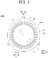
- the power line terminals 61 for the U1 coil portion 31 and U2 coil portion 32 and the power line terminals 61 for the U3 coil portion 33 and U4 coil portion 34 are set at diagonal positions in the circumferential direction, as shown in FIG. 3B .
- the first crossover portions 23 that form one of the wave winding portions forming one lap out of the wave winding portions 20a to 20d and the first crossover portions 23 that form the other of the wave winding portions forming the lap connect the slot insertion portions 21 in pairs so that the radial positions of the connected slot insertion portions 21 are changed gradually (like a slope) and parallel to each other.
- the number (pitch) of slots 11 across which each first crossover portion 23 extends is the same in each of the plurality of wave winding portions 20a to 20d. Specifically, each of the first crossover portions 23 extends across five slots 11 to connect the slot insertion portions 21 while shifting the turn by one.
- the pitch of all the first crossover portions 23 is "6."
- the first crossover portions 23 have the same pitch both on the one side (Z1 direction side) and the other side (Z2 direction side) of the stator core 10.
- parallel means that the radial positions of the slot insertion portions 21 connected to the first crossover portions 23 are parallel in a state in which the slot insertion portions 21 are installed along the circumferential direction. That is, this means that the positions of the slot insertion portions 21 are parallel when the annular stator core 10 is shown opened out flat as in FIGS. 4 to 7 .
- the slot insertion portions 21 forming the wave winding portions 20a to 20d are housed in pairs of slots 11 that are adjacent to each other in the circumferential direction, namely #1 and #48, #6 and #7, #12 and #13, #18 and #19, #24 and #25, #30 and #31, #36 and #37, and #42 and #43.
- the slot insertion portions 21 are alternately installed in different slots 11.
- the three types of coil pieces 70 that form a pair of slot insertion portions 21 and a first crossover portion 23 are the following three types of coil pieces 70: a coil piece 70 whose first crossover portion 23 connects the second turn and the third turn on the Z1 direction side, a coil piece 70 whose first crossover portion 23 connects the fourth turn and the fifth turn on the Z1 direction side, and a coil piece 70 whose first crossover portion 23 connects the sixth turn and the seventh turn on the Z1 direction side.
- the two types of coil pieces 70 that form a pair of slot insertion portions 21 and a second crossover portion 24 and the two types of coil pieces 70 that form a pair of slot insertion portions 21 and a third crossover portion 25 each have two different pitches, namely 5 and 7.
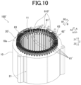
- FIG. 10 is a perspective view of a stator 100' according to the comparative example.
- the stator 100' according to the comparative example is different in that part of power line terminals 61' and neutral line terminals 62' are disposed radially inward of the stator core 10.
- the power line terminals 61 and neutral line terminals 62 of each phase are all disposed radially outward of the stator core 10.
- This configuration can avoid the disadvantage that occurs when at least one power line terminal 61 is disposed on the radially inner side. That is, unlike the comparative example described above with reference to FIG. 10 , an increase in axial size of the stator 100 due to the stator coil 20 can be prevented.
- the present embodiment can reduce the axial size of the stator 100 while setting the number of parallel-connected coil portions of each phase to four.
- the power line terminals 61 can be disposed axially inward of the axially outermost position of the crossover portions 22 (i.e., the axially outermost position of the coil end, see line L3) as viewed in the radial direction. This can prevent an increase in axial size of the stator 100 due to the power line terminals 61, and thus can reduce the axial size of the stator 100.
- wires connected to the power line terminals 61 namely wires connected to an inverter, not shown (e.g., wires in the form of a cable) can also be disposed axially inward of the axially outermost position of the crossover portions 22 as viewed in the radial direction.
- the neutral line terminals 62 and neutral point busbars 63 connecting the neutral line terminals 62 can be disposed axially inward of the axially outermost position of the crossover portions 22 (i.e., the axially outermost position of the coil end, see line L3) as viewed in the radial direction.
- This can prevent an increase in axial size of the stator 100 due to the neutral line terminals 62 and the neutral point busbars 63 connecting the neutral line terminals 62, and thus can reduce the axial size of the stator 100.
- the present embodiment has the following effects in addition to the above effects.
- the first crossover portions 23 form the wave winding portions 20a to 20d that are wave-wound around the stator core 10 together with the slot insertion portions 21 by connecting the slot insertion portions 21 in pairs so that the radial positions of the connected slot insertion portions 21 are gradually changed in order toward the one side in the radial direction. It is therefore possible to connect the slot insertion portions 21 without providing a portion where the radial position of the connected slot insertion portions 21 is switched at an intermediate position, unlike the case where radially adjacent slot insertion portions 21 are alternately connected in each of the plurality of slots 11.
- the second crossover portion 24 and the third crossover portion 25 connect the slot insertion portions 21 in pairs, so that one and the other of the wave winding portions forming one lap out of the wave winding portions 20a to 20d formed by the first crossover portions 23 and the slot insertion portions 21 are connected so as to be folded back.
- the second crossover portion 24 and the third crossover portion 25, each connecting the slot insertion portions 21 installed at the same radial position in the slots 11, can thus connect the wave winding portions 20a to 20d so as to fold back the wave winding portions 20a to 20d. This can prevent the shape of the folded-back portions from becoming complicated.
- one and the other of the wave winding portions forming one lap out of the wave winding portions 20a to 20d are installed so that the radial positions of the connected slot insertion portions 21 are changed gradually and parallel to each other. Therefore, the conductors (coil pieces 70) having the same shape can be used as conductors forming one of the wave winding portions forming one lap out of the wave winding portions 20a to 20d and conductors forming the other wave winding portion. This can reduce the number of types of coil pieces 70 for forming the stator coil 20, even when the wave winding portions forming one lap out of the wave winding portions 20a to 20d are connected so as to be folded back.
- the wave-wound stator coil 20 folded back a plurality of times is formed using the plurality of wave winding portions 20a to 20d, the second crossover portions 24 (outermost coil end portion), and the third crossover portions 25 (innermost coil end portion). Therefore, the stator coil 20 can be formed so as to be wave-wound by folding back a plurality of times on each of the radially innermost and outermost sides in the slots 11. Accordingly, even when a large number of slot insertion portions 21 is housed in one slot 11, the stator coil 20 can be formed by folding back a plurality of times on each of the radially innermost and outermost sides in the slots 11. This can reduce an increase in number of types of coil pieces 70 that form the stator coil 20.
- the stator coil 20 can be formed by connecting pairs of slot insertion portions 21 installed at positions shifted outward or inward in the radial direction from each other by one. Therefore, the slot insertion portions 21 can be densely installed in each of the plurality of slots 11. Accordingly, the slot insertion portions 21 can be connected in pairs so that the radial positions of the connected slot insertion portions 21 are gradually changed in order toward the one side in the radial direction, while allowing efficient connection of the plurality of slot insertion portions 21 installed in the slots 11.
- the slot insertion portions 21 are installed in the same slots 11 in both one and the other of the wave winding portions forming one lap out of the wave winding portions 20a to 20d, the positional relationship of the stator coil 20 with the magnets installed in the rotor 150 facing the stator 100 becomes uneven. Therefore, currents flowing through the wave winding portions 20a to 20d become uneven.
- the slot insertion portions 21 forming one of the wave winding portions forming one lap out of the wave winding portions 20a to 20d and the slot insertion portions 21 forming the other of the wave winding portions forming the lap out of the wave winding portions 20a to 20d are installed in adjacent slots 11. Therefore, currents flowing through the wave winding portions 20a to 20d are less likely to become uneven.
- all of the neutral line terminals 62 are also disposed on the radially outer side.
- part or all of the neutral line terminals 62 may be disposed radially inward of the stator core 10. That is, part or all of the second slot insertion portions 21B may be installed on the radially outermost side in the slots 11.
- the above embodiment illustrates an example in which the first crossover portions 23 that form one of the wave winding portions forming one lap out of the wave winding portions 20a to 20d and the first crossover portions 23 that form the other wave winding portion are provided so that the radial positions of the connected slot insertion portions 21 are changed gradually and parallel to each other.
- the present disclosure is not limited to this.
- the radial positions of the slot insertion portions 21 in one of the wave winding portions forming one lap may not be parallel to the radial positions of the slot insertion portions 21 in the other wave winding portion.
- the above embodiment illustrates an example in which the wave winding portions 20a to 20d are folded back on the radially outermost and innermost sides.
- the present disclosure is not limited to this.
- the wave winding portions 20a to 20d may be folded back at an intermediate position in the radial direction.
Landscapes
- Engineering & Computer Science (AREA)
- Power Engineering (AREA)
- Windings For Motors And Generators (AREA)
Applications Claiming Priority (2)
| Application Number | Priority Date | Filing Date | Title |
|---|---|---|---|
| JP2022167302A JP7806652B2 (ja) | 2022-10-19 | 2022-10-19 | 回転電機用ステータ |
| PCT/JP2023/035862 WO2024084934A1 (ja) | 2022-10-19 | 2023-10-02 | 回転電機用ステータ |
Publications (2)
| Publication Number | Publication Date |
|---|---|
| EP4576507A1 true EP4576507A1 (de) | 2025-06-25 |
| EP4576507A4 EP4576507A4 (de) | 2025-12-10 |
Family
ID=90737714
Family Applications (1)
| Application Number | Title | Priority Date | Filing Date |
|---|---|---|---|
| EP23879581.9A Pending EP4576507A4 (de) | 2022-10-19 | 2023-10-02 | Stator für eine elektrische drehmaschine |
Country Status (4)
| Country | Link |
|---|---|
| EP (1) | EP4576507A4 (de) |
| JP (1) | JP7806652B2 (de) |
| CN (1) | CN119923784A (de) |
| WO (1) | WO2024084934A1 (de) |
Families Citing this family (1)
| Publication number | Priority date | Publication date | Assignee | Title |
|---|---|---|---|---|
| WO2025248682A1 (ja) * | 2024-05-29 | 2025-12-04 | Astemo株式会社 | 回転電機の固定子、回転電機 |
Family Cites Families (6)
| Publication number | Priority date | Publication date | Assignee | Title |
|---|---|---|---|---|
| JP6410104B2 (ja) | 2015-07-31 | 2018-10-24 | 株式会社デンソー | 回転電機の固定子及びその固定子を備えた回転電機 |
| CN109586458B (zh) * | 2017-09-29 | 2021-04-20 | 比亚迪股份有限公司 | 定子组件和具有其的电机和车辆 |
| CN109586463B (zh) | 2017-09-29 | 2021-08-10 | 比亚迪股份有限公司 | 定子组件和具有其的电机和车辆 |
| JP7070075B2 (ja) | 2018-05-16 | 2022-05-18 | 株式会社アイシン | 回転電機 |
| CN111478465B (zh) * | 2020-05-26 | 2025-06-03 | 上海威迈斯新能源有限公司 | 扁线定子组件及电机 |
| JP2022136858A (ja) | 2021-03-08 | 2022-09-21 | 日本電産株式会社 | モータ |
-
2022
- 2022-10-19 JP JP2022167302A patent/JP7806652B2/ja active Active
-
2023
- 2023-10-02 EP EP23879581.9A patent/EP4576507A4/de active Pending
- 2023-10-02 WO PCT/JP2023/035862 patent/WO2024084934A1/ja not_active Ceased
- 2023-10-02 CN CN202380066908.XA patent/CN119923784A/zh active Pending
Also Published As
| Publication number | Publication date |
|---|---|
| EP4576507A4 (de) | 2025-12-10 |
| CN119923784A (zh) | 2025-05-02 |
| JP2024060143A (ja) | 2024-05-02 |
| WO2024084934A1 (ja) | 2024-04-25 |
| JP7806652B2 (ja) | 2026-01-27 |
Similar Documents
| Publication | Publication Date | Title |
|---|---|---|
| CN109075647B (zh) | 旋转电机 | |
| US9866083B2 (en) | Stator for rotating electric machine | |
| JP2004229459A (ja) | 回転電機の集中巻きステータコイル | |
| JP7655756B2 (ja) | モータ | |
| JP7817940B2 (ja) | ステータおよびモータ | |
| EP2690757A2 (de) | Ring zur elektrischen Verbindung sowie Elektromotor | |
| JP7549007B2 (ja) | 波巻のコイル構造を有する固定子、これを備える三相交流電動機及び固定子の製造方法 | |
| CN111478477A (zh) | 一种电机定子及电机 | |
| CN115051492A (zh) | 马达 | |
| CN213990307U (zh) | 一种电机定子及电机 | |
| CN111478478A (zh) | 一种电机定子及电机 | |
| CN115459497A (zh) | 马达 | |
| EP1035630A2 (de) | Rotierende elektrische Maschine und Verfahren zum Verbinden von Spulen | |
| CN115133690A (zh) | 定子和马达 | |
| EP4576507A1 (de) | Stator für eine elektrische drehmaschine | |
| CN104364997A (zh) | 旋转电机、旋转电机用定子和车辆 | |
| CN112583168A (zh) | 一种电机定子绕组、定子及电机 | |
| CN104364996B (zh) | 旋转电机、旋转电机用定子和车辆 | |
| US20260058505A1 (en) | Stator, electrical rotating machine, stator winding method, and stator manufacturing method | |
| CN111478486A (zh) | 一种电机定子及电机 | |
| CN111478480A (zh) | 一种电机定子及电机 | |
| CN115242001A (zh) | 发夹形导线马达定子 | |
| CN111478479A (zh) | 一种电机定子及电机 | |
| CN211908498U (zh) | 一种电机定子及电机 | |
| CN211880197U (zh) | 一种电机定子及电机 |
Legal Events
| Date | Code | Title | Description |
|---|---|---|---|
| STAA | Information on the status of an ep patent application or granted ep patent |
Free format text: STATUS: THE INTERNATIONAL PUBLICATION HAS BEEN MADE |
|
| PUAI | Public reference made under article 153(3) epc to a published international application that has entered the european phase |
Free format text: ORIGINAL CODE: 0009012 |
|
| STAA | Information on the status of an ep patent application or granted ep patent |
Free format text: STATUS: REQUEST FOR EXAMINATION WAS MADE |
|
| 17P | Request for examination filed |
Effective date: 20250317 |
|
| AK | Designated contracting states |
Kind code of ref document: A1 Designated state(s): AL AT BE BG CH CY CZ DE DK EE ES FI FR GB GR HR HU IE IS IT LI LT LU LV MC ME MK MT NL NO PL PT RO RS SE SI SK SM TR |
|
| A4 | Supplementary search report drawn up and despatched |
Effective date: 20251110 |
|
| RIC1 | Information provided on ipc code assigned before grant |
Ipc: H02K 3/28 20060101AFI20251104BHEP Ipc: H02K 3/50 20060101ALI20251104BHEP Ipc: H02K 3/12 20060101ALN20251104BHEP |
|
| DAV | Request for validation of the european patent (deleted) | ||
| DAX | Request for extension of the european patent (deleted) |