EP4576516A2 - Motif d'enroulement de bobine pour une efficacité de moteur améliorée - Google Patents
Motif d'enroulement de bobine pour une efficacité de moteur améliorée Download PDFInfo
- Publication number
- EP4576516A2 EP4576516A2 EP25174836.4A EP25174836A EP4576516A2 EP 4576516 A2 EP4576516 A2 EP 4576516A2 EP 25174836 A EP25174836 A EP 25174836A EP 4576516 A2 EP4576516 A2 EP 4576516A2
- Authority
- EP
- European Patent Office
- Prior art keywords
- coil
- stator winding
- coils
- phase
- electric motor
- Prior art date
- Legal status (The legal status is an assumption and is not a legal conclusion. Google has not performed a legal analysis and makes no representation as to the accuracy of the status listed.)
- Pending
Links
Images




Classifications
-
- A—HUMAN NECESSITIES
- A61—MEDICAL OR VETERINARY SCIENCE; HYGIENE
- A61M—DEVICES FOR INTRODUCING MEDIA INTO, OR ONTO, THE BODY; DEVICES FOR TRANSDUCING BODY MEDIA OR FOR TAKING MEDIA FROM THE BODY; DEVICES FOR PRODUCING OR ENDING SLEEP OR STUPOR
- A61M60/00—Blood pumps; Devices for mechanical circulatory actuation; Balloon pumps for circulatory assistance
- A61M60/40—Details relating to driving
- A61M60/403—Details relating to driving for non-positive displacement blood pumps
- A61M60/419—Details relating to driving for non-positive displacement blood pumps the force acting on the blood contacting member being permanent magnetic, e.g. from a rotating magnetic coupling between driving and driven magnets
-
- A—HUMAN NECESSITIES
- A61—MEDICAL OR VETERINARY SCIENCE; HYGIENE
- A61M—DEVICES FOR INTRODUCING MEDIA INTO, OR ONTO, THE BODY; DEVICES FOR TRANSDUCING BODY MEDIA OR FOR TAKING MEDIA FROM THE BODY; DEVICES FOR PRODUCING OR ENDING SLEEP OR STUPOR
- A61M60/00—Blood pumps; Devices for mechanical circulatory actuation; Balloon pumps for circulatory assistance
- A61M60/10—Location thereof with respect to the patient's body
- A61M60/122—Implantable pumps or pumping devices, i.e. the blood being pumped inside the patient's body
- A61M60/126—Implantable pumps or pumping devices, i.e. the blood being pumped inside the patient's body implantable via, into, inside, in line, branching on, or around a blood vessel
- A61M60/13—Implantable pumps or pumping devices, i.e. the blood being pumped inside the patient's body implantable via, into, inside, in line, branching on, or around a blood vessel by means of a catheter allowing explantation, e.g. catheter pumps temporarily introduced via the vascular system
-
- A—HUMAN NECESSITIES
- A61—MEDICAL OR VETERINARY SCIENCE; HYGIENE
- A61M—DEVICES FOR INTRODUCING MEDIA INTO, OR ONTO, THE BODY; DEVICES FOR TRANSDUCING BODY MEDIA OR FOR TAKING MEDIA FROM THE BODY; DEVICES FOR PRODUCING OR ENDING SLEEP OR STUPOR
- A61M60/00—Blood pumps; Devices for mechanical circulatory actuation; Balloon pumps for circulatory assistance
- A61M60/10—Location thereof with respect to the patient's body
- A61M60/122—Implantable pumps or pumping devices, i.e. the blood being pumped inside the patient's body
- A61M60/126—Implantable pumps or pumping devices, i.e. the blood being pumped inside the patient's body implantable via, into, inside, in line, branching on, or around a blood vessel
- A61M60/135—Implantable pumps or pumping devices, i.e. the blood being pumped inside the patient's body implantable via, into, inside, in line, branching on, or around a blood vessel inside a blood vessel, e.g. using grafting
-
- A—HUMAN NECESSITIES
- A61—MEDICAL OR VETERINARY SCIENCE; HYGIENE
- A61M—DEVICES FOR INTRODUCING MEDIA INTO, OR ONTO, THE BODY; DEVICES FOR TRANSDUCING BODY MEDIA OR FOR TAKING MEDIA FROM THE BODY; DEVICES FOR PRODUCING OR ENDING SLEEP OR STUPOR
- A61M60/00—Blood pumps; Devices for mechanical circulatory actuation; Balloon pumps for circulatory assistance
- A61M60/10—Location thereof with respect to the patient's body
- A61M60/122—Implantable pumps or pumping devices, i.e. the blood being pumped inside the patient's body
- A61M60/126—Implantable pumps or pumping devices, i.e. the blood being pumped inside the patient's body implantable via, into, inside, in line, branching on, or around a blood vessel
- A61M60/135—Implantable pumps or pumping devices, i.e. the blood being pumped inside the patient's body implantable via, into, inside, in line, branching on, or around a blood vessel inside a blood vessel, e.g. using grafting
- A61M60/139—Implantable pumps or pumping devices, i.e. the blood being pumped inside the patient's body implantable via, into, inside, in line, branching on, or around a blood vessel inside a blood vessel, e.g. using grafting inside the aorta, e.g. intra-aortic balloon pumps
-
- A—HUMAN NECESSITIES
- A61—MEDICAL OR VETERINARY SCIENCE; HYGIENE
- A61M—DEVICES FOR INTRODUCING MEDIA INTO, OR ONTO, THE BODY; DEVICES FOR TRANSDUCING BODY MEDIA OR FOR TAKING MEDIA FROM THE BODY; DEVICES FOR PRODUCING OR ENDING SLEEP OR STUPOR
- A61M60/00—Blood pumps; Devices for mechanical circulatory actuation; Balloon pumps for circulatory assistance
- A61M60/10—Location thereof with respect to the patient's body
- A61M60/122—Implantable pumps or pumping devices, i.e. the blood being pumped inside the patient's body
- A61M60/126—Implantable pumps or pumping devices, i.e. the blood being pumped inside the patient's body implantable via, into, inside, in line, branching on, or around a blood vessel
- A61M60/148—Implantable pumps or pumping devices, i.e. the blood being pumped inside the patient's body implantable via, into, inside, in line, branching on, or around a blood vessel in line with a blood vessel using resection or like techniques, e.g. permanent endovascular heart assist devices
-
- A—HUMAN NECESSITIES
- A61—MEDICAL OR VETERINARY SCIENCE; HYGIENE
- A61M—DEVICES FOR INTRODUCING MEDIA INTO, OR ONTO, THE BODY; DEVICES FOR TRANSDUCING BODY MEDIA OR FOR TAKING MEDIA FROM THE BODY; DEVICES FOR PRODUCING OR ENDING SLEEP OR STUPOR
- A61M60/00—Blood pumps; Devices for mechanical circulatory actuation; Balloon pumps for circulatory assistance
- A61M60/10—Location thereof with respect to the patient's body
- A61M60/122—Implantable pumps or pumping devices, i.e. the blood being pumped inside the patient's body
- A61M60/165—Implantable pumps or pumping devices, i.e. the blood being pumped inside the patient's body implantable in, on, or around the heart
-
- A—HUMAN NECESSITIES
- A61—MEDICAL OR VETERINARY SCIENCE; HYGIENE
- A61M—DEVICES FOR INTRODUCING MEDIA INTO, OR ONTO, THE BODY; DEVICES FOR TRANSDUCING BODY MEDIA OR FOR TAKING MEDIA FROM THE BODY; DEVICES FOR PRODUCING OR ENDING SLEEP OR STUPOR
- A61M60/00—Blood pumps; Devices for mechanical circulatory actuation; Balloon pumps for circulatory assistance
- A61M60/20—Type thereof
- A61M60/205—Non-positive displacement blood pumps
- A61M60/216—Non-positive displacement blood pumps including a rotating member acting on the blood, e.g. impeller
-
- A—HUMAN NECESSITIES
- A61—MEDICAL OR VETERINARY SCIENCE; HYGIENE
- A61M—DEVICES FOR INTRODUCING MEDIA INTO, OR ONTO, THE BODY; DEVICES FOR TRANSDUCING BODY MEDIA OR FOR TAKING MEDIA FROM THE BODY; DEVICES FOR PRODUCING OR ENDING SLEEP OR STUPOR
- A61M60/00—Blood pumps; Devices for mechanical circulatory actuation; Balloon pumps for circulatory assistance
- A61M60/20—Type thereof
- A61M60/205—Non-positive displacement blood pumps
- A61M60/216—Non-positive displacement blood pumps including a rotating member acting on the blood, e.g. impeller
- A61M60/237—Non-positive displacement blood pumps including a rotating member acting on the blood, e.g. impeller the blood flow through the rotating member having mainly axial components, e.g. axial flow pumps
-
- A—HUMAN NECESSITIES
- A61—MEDICAL OR VETERINARY SCIENCE; HYGIENE
- A61M—DEVICES FOR INTRODUCING MEDIA INTO, OR ONTO, THE BODY; DEVICES FOR TRANSDUCING BODY MEDIA OR FOR TAKING MEDIA FROM THE BODY; DEVICES FOR PRODUCING OR ENDING SLEEP OR STUPOR
- A61M60/00—Blood pumps; Devices for mechanical circulatory actuation; Balloon pumps for circulatory assistance
- A61M60/40—Details relating to driving
- A61M60/403—Details relating to driving for non-positive displacement blood pumps
- A61M60/408—Details relating to driving for non-positive displacement blood pumps the force acting on the blood contacting member being mechanical, e.g. transmitted by a shaft or cable
- A61M60/411—Details relating to driving for non-positive displacement blood pumps the force acting on the blood contacting member being mechanical, e.g. transmitted by a shaft or cable generated by an electromotor
- A61M60/416—Details relating to driving for non-positive displacement blood pumps the force acting on the blood contacting member being mechanical, e.g. transmitted by a shaft or cable generated by an electromotor transmitted directly by the motor rotor drive shaft
-
- A—HUMAN NECESSITIES
- A61—MEDICAL OR VETERINARY SCIENCE; HYGIENE
- A61M—DEVICES FOR INTRODUCING MEDIA INTO, OR ONTO, THE BODY; DEVICES FOR TRANSDUCING BODY MEDIA OR FOR TAKING MEDIA FROM THE BODY; DEVICES FOR PRODUCING OR ENDING SLEEP OR STUPOR
- A61M60/00—Blood pumps; Devices for mechanical circulatory actuation; Balloon pumps for circulatory assistance
- A61M60/40—Details relating to driving
- A61M60/403—Details relating to driving for non-positive displacement blood pumps
- A61M60/422—Details relating to driving for non-positive displacement blood pumps the force acting on the blood contacting member being electromagnetic, e.g. using canned motor pumps
-
- A—HUMAN NECESSITIES
- A61—MEDICAL OR VETERINARY SCIENCE; HYGIENE
- A61M—DEVICES FOR INTRODUCING MEDIA INTO, OR ONTO, THE BODY; DEVICES FOR TRANSDUCING BODY MEDIA OR FOR TAKING MEDIA FROM THE BODY; DEVICES FOR PRODUCING OR ENDING SLEEP OR STUPOR
- A61M60/00—Blood pumps; Devices for mechanical circulatory actuation; Balloon pumps for circulatory assistance
- A61M60/80—Constructional details other than related to driving
- A61M60/855—Constructional details other than related to driving of implantable pumps or pumping devices
- A61M60/857—Implantable blood tubes
-
- H—ELECTRICITY
- H02—GENERATION; CONVERSION OR DISTRIBUTION OF ELECTRIC POWER
- H02K—DYNAMO-ELECTRIC MACHINES
- H02K1/00—Details of the magnetic circuit
- H02K1/06—Details of the magnetic circuit characterised by the shape, form or construction
- H02K1/12—Stationary parts of the magnetic circuit
-
- H—ELECTRICITY
- H02—GENERATION; CONVERSION OR DISTRIBUTION OF ELECTRIC POWER
- H02K—DYNAMO-ELECTRIC MACHINES
- H02K1/00—Details of the magnetic circuit
- H02K1/06—Details of the magnetic circuit characterised by the shape, form or construction
- H02K1/22—Rotating parts of the magnetic circuit
- H02K1/27—Rotor cores with permanent magnets
- H02K1/2706—Inner rotors
- H02K1/272—Inner rotors the magnetisation axis of the magnets being perpendicular to the rotor axis
- H02K1/274—Inner rotors the magnetisation axis of the magnets being perpendicular to the rotor axis the rotor consisting of two or more circumferentially positioned magnets
- H02K1/2753—Inner rotors the magnetisation axis of the magnets being perpendicular to the rotor axis the rotor consisting of two or more circumferentially positioned magnets the rotor consisting of magnets or groups of magnets arranged with alternating polarity
-
- H—ELECTRICITY
- H02—GENERATION; CONVERSION OR DISTRIBUTION OF ELECTRIC POWER
- H02K—DYNAMO-ELECTRIC MACHINES
- H02K1/00—Details of the magnetic circuit
- H02K1/06—Details of the magnetic circuit characterised by the shape, form or construction
- H02K1/22—Rotating parts of the magnetic circuit
- H02K1/27—Rotor cores with permanent magnets
- H02K1/2706—Inner rotors
- H02K1/272—Inner rotors the magnetisation axis of the magnets being perpendicular to the rotor axis
- H02K1/274—Inner rotors the magnetisation axis of the magnets being perpendicular to the rotor axis the rotor consisting of two or more circumferentially positioned magnets
- H02K1/2753—Inner rotors the magnetisation axis of the magnets being perpendicular to the rotor axis the rotor consisting of two or more circumferentially positioned magnets the rotor consisting of magnets or groups of magnets arranged with alternating polarity
- H02K1/278—Surface mounted magnets; Inset magnets
-
- H—ELECTRICITY
- H02—GENERATION; CONVERSION OR DISTRIBUTION OF ELECTRIC POWER
- H02K—DYNAMO-ELECTRIC MACHINES
- H02K3/00—Details of windings
- H02K3/04—Windings characterised by the conductor shape, form or construction, e.g. with bar conductors
- H02K3/28—Layout of windings or of connections between windings
-
- H—ELECTRICITY
- H02—GENERATION; CONVERSION OR DISTRIBUTION OF ELECTRIC POWER
- H02K—DYNAMO-ELECTRIC MACHINES
- H02K3/00—Details of windings
- H02K3/46—Fastening of windings on the stator or rotor structure
- H02K3/47—Air-gap windings, i.e. iron-free windings
-
- H—ELECTRICITY
- H02—GENERATION; CONVERSION OR DISTRIBUTION OF ELECTRIC POWER
- H02K—DYNAMO-ELECTRIC MACHINES
- H02K7/00—Arrangements for handling mechanical energy structurally associated with dynamo-electric machines, e.g. structural association with mechanical driving motors or auxiliary dynamo-electric machines
- H02K7/14—Structural association with mechanical loads, e.g. with hand-held machine tools or fans
-
- A—HUMAN NECESSITIES
- A61—MEDICAL OR VETERINARY SCIENCE; HYGIENE
- A61M—DEVICES FOR INTRODUCING MEDIA INTO, OR ONTO, THE BODY; DEVICES FOR TRANSDUCING BODY MEDIA OR FOR TAKING MEDIA FROM THE BODY; DEVICES FOR PRODUCING OR ENDING SLEEP OR STUPOR
- A61M2205/00—General characteristics of the apparatus
- A61M2205/10—General characteristics of the apparatus with powered movement mechanisms
- A61M2205/103—General characteristics of the apparatus with powered movement mechanisms rotating
-
- H—ELECTRICITY
- H02—GENERATION; CONVERSION OR DISTRIBUTION OF ELECTRIC POWER
- H02K—DYNAMO-ELECTRIC MACHINES
- H02K2213/00—Specific aspects, not otherwise provided for and not covered by codes H02K2201/00 - H02K2211/00
- H02K2213/03—Machines characterised by numerical values, ranges, mathematical expressions or similar information
Definitions
- Intravascular blood pumps such as the Impella ® pump by Abiomed, Inc. of Danvers, MA, are quickly becoming the current standard for ventricular assist devices.
- the range of Impella ® pumps currently comprises the Impella 2.5 ® pump, the Impella 5.0 ® pump, the Impella CP ® pump and the Impella LD ® pump.
- These pumps are inserted into a patient percutaneously through a single access point (e.g. radial access, femoral access, axillary access) such that the pump head can be placed into a desired location within the patient's body via small diameter (6-7Fr) catheters.
- desired locations include, but are not limited to, the left or right ventricle of the patient's heart.
- the pump head comprises an electric motor that includes a stator winding configured to magnetically interact with a rotor for rotation thereof resulting in a volumetric flow of blood through the rotor and hence through the heart of the patient. Efficient motors that produce good flow rates are sought.
- the motor comprises a stator winding having 2np coils wound to form two coils per phase per magnet pole pair such that a coil from each phase is circumferentially arranged next to a coil from a different phase in a sequential order of phase, the arrangement repeated along the stator winding such that each coil of the 2np coils spans 360/(2 np ) mechanical degrees about the cross section of the stator winding.
- the motor also comprises a permanent magnet rotor supported for rotation and configured to generate a magnetic flux for interaction with the stator winding.
- a slotless permanent magnet electric motor having p magnet pole pairs and n phases, where p is an integer greater than zero, and n is an integer ⁇ 3, the motor having a longitudinal axis.
- the motor comprises a stator winding having 2np coils wound to form two coils per phase per magnet pole pair such that a coil from each phase is circumferentially arranged next to a coil from a different phase in a sequential order of phase, the arrangement repeated along the stator winding such that each coil of the 2np coils spans 360/(2 np ) mechanical degrees about the cross section of the stator winding.
- the motor also comprises a permanent magnet rotor supported for rotation and configured to generate a magnetic flux for interaction with the stator winding.
- each of the coils comprise either N /2 turns for even values of N, or ( N ⁇ 1)/2 for odd values of N, where N is the number of winding turns in a coil of a conventional stator winding having np coils wound to form one coil per phase per magnet pole pair, where N is an integer ⁇ 1.
- the resistance of the two coils connected in series per phase is equivalent to the resistance of a single coil of the conventional stator winding.
- the two coils per phase are connected in series such that their start terminals or their end terminals are connected together.
- stator windings employ two coils per phase per magnet pole pair, connected as described above. This provides for a 15.5% increase in torque constant in electric motors using such stator windings when compared to conventional electric motors having stator windings with one coil per phase per magnet pole pair. Such a stator configuration does not increase the resistive load on the stator, and thus reduces joule heating within the electric motor. In effect the electric motor of the present disclosure provides for a stator coil winding pattern with enhanced motor efficiency.
- the blood pump is configured such that the two coils per phase per magnet pole pair of the stator winding are connected in series such that a direction of current flow through a first coil of the two coils is opposite to a direction of current flow in a second coil of the two coils, the current flow in the first coil and the current flow in the second coil interacting with opposite polarities of the magnetic flux of the rotor for producing torque in the same direction, thereby facilitating rotation of the rotor for the flow of blood through the pump.
- FIG. 1 illustrates an exemplary intravascular blood pump 100 for insertion into the body of a patient, according to an embodiment of the present disclosure.
- Blood pump 100 comprises a motor unit 110 and a pump unit 120 arranged along a longitudinal axis 105.
- the motor unit 110 comprises an electric motor including a stator winding 140 and a rotor 150 contained within a housing 112.
- the stator winding 140 extends along the length of the motor unit 110 from a proximal end 142 to a distal end 143, and comprises wires 144 wound in a particular pattern, the details of which will be provided below.
- the stator winding 140 defines a central lumen 145 in which the rotor 150 is positioned.
- the stator winding 140 is slotless such that the wires 144 are wound upon themselves and not onto a conventional laminated stator core.
- Feed lines 146, 147 provide the necessary electrical connections externally from the pump 100 to the stator winding 140 for operation of the motor unit 110.
- Each of the wires 144 may have an insulating coating (not shown), and, optionally, the wound stator wires 144 may be encapsulated or over-molded by a synthetic epoxide resin (also not shown).
- stator winding 140 and the housing 112 are depicted as separate components, however it will be understood that the stator winding 140 may be encapsulated within the housing 112 to form a single component.
- the housing 112 comprises a proximal end 114 and a distal end 116.
- the proximal end 114 of the housing 112 is coupled to a distal end 134 of a catheter 130 which may comprise a flexible tube.
- Catheter 130 comprises a lumen 132 which extends towards the physician for control and operation of the blood pump 100.
- the rotor 150 comprises a permanent magnet 152 that is rotationally supported about a shaft 153 within the lumen 145 of the stator 140.
- Magnet 152 may comprise a cylindrical permanent magnet that surrounds the shaft 153 within the motor unit 110.
- Shaft 153 extends from the motor unit 110 into the pump unit 120 and facilitates rotation of an impeller 160 for the pumping of blood.
- the rotor 150 may comprise several permanent magnets radially arranged about the shaft 153, or an electromagnetic magnet having its own rotor windings.
- the magnet 152 may comprise one north pole N and one south pole S.
- the magnet 152 may comprise two north poles N1 and N2, and two south poles, S1 and S2, arranged alternately around the shaft 153.
- FIG. 1 illustrates the rotor 150 as rotatable within the stator 140
- the electric motor 110 may be configured such that the stator 140 is held stationary about the shaft 153 and the rotor 150 is configured as a cylinder that rotates around the stator 140.
- Shaft 153 extends along the length of the motor unit 110 and extends into a cylindrical housing 122 of the pump unit 120.
- the shaft 153 may be hollow and comprise a lumen 154 for the passage of a guidewire, for example.
- the distal end of the shaft 153 is coupled to an impeller 160 located within the pump housing 112.
- Interaction between the stator 140 and rotor 150 of the motor unit 110 generates torque in the rotor 150 causing the shaft 153 to rotate, which, in turn, causes the impeller 160 to rotate in the cylindrical pump housing 122.
- blood is sucked into the pump via an axial intake opening 124 for conveyance in the axial direction, the blood issuing laterally from the openings 126 and flowing axially along housing 112. In this manner the pump 100 generates a flow of blood within the heart of the patient.
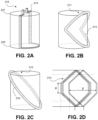
- FIGS. 2A-2D illustrate exemplary stator winding patterns 210-213 according to an embodiment of the present disclosure.
- the coil winding patterns for a single wire in a stator are shown, such as wires 142 in FIG. 1 , however it will be understood that the complete stator winding, such as stator winding 140 in FIG. 1 , will be obtained by the axial arrangement of a plurality of similarly wound wires about a longitudinal axis of the motor unit 110, such as the longitudinal axis 105 in FIG. 1 .
- FIGS. 2A-2D illustrate exemplary coil winding patterns employed in two-pole electric machines in which one mechanical degree is equal to one electrical degree.
- the coil winding patterns in FIGS. 2A-2D may be used to form the stator winding 140 of the motor unit 110 in FIG. 1 .
- FIG. 2A shows a conventional stator winding pattern 210 in which each wire 214 in the stator extends from a proximal end 221, along the length of the stator 220, to a distal end 225. At the distal end 225, the wire 214 follows the external perimeter of the stator for 180 mechanical degrees and returns to the proximal end 221.
- FIG. 2B shows a rhombic stator winding pattern 211 in which each wire 215 is arranged in a bent configuration.
- the rhombic winding comprises one continuous wire that is wound several times over, each complete turn shifted axially to form the stator coil.
- the bent configuration of the rhombic winding may require post-assembly.
- FIG. 2C shows a helical stator winding pattern 212 in which each wire 216 is arranged in an elliptical configuration around the stator.
- the helical stator winding pattern 212 is similar to the rhombic winding pattern 211 in FIG. 2B but without the bend which simplifies the coil winding process.
- the helical winding 212 is a one-step winding which can be easily formed without the need for any post-assembly steps.
- FIG. 2D shows a hybrid stator winding pattern 213 that comprises a winding that is a mixture of the conventional windings as shown in FIG. 2A and the rhombic windings as shown in FIG. 2B .
- Such a hybrid stator winding allows for the optimum ratio of torque to resistance by adjusting the vertical length, x, and/or horizontal angular span, y, of the coil.
- stator windings in the present disclosure may employ any of winding patterns as described in relation to FIGS. 2A-2D . Further, in some implementations of the present disclosure, any other stator winding patterns may be employed.
- FIGS. 3A and 3B illustrate cross sections of exemplary stator windings for use in an electric motor, such as stator winding 140 of motor unit 110 in FIG. 1 .
- FIG. 3A shows a conventional stator winding 300 comprising one coil per phase per permanent magnet pole pair for use in a three-phase electric motor having one pole pair (i.e. one north pole N and one south pole S).
- the three phases of the electric motor are referred to as phases A, B and C.
- each phase comprises one coil - coil 310 (labelled 'A') for phase A, coil 311 (labelled 'B') for phase B, and coil 312 (labeled 'C') for phase C.
- Each of the coils 310-312 comprises a winding having a plurality of N turns, where N is an integer and N > 1, where each coil has the same number of turns.
- the windings are formed from wires that have been turned in a specific manner, such as that described in relation to FIGS. 2A-2D , thereby resulting in each coil having a start point and an end point, as indicated by the wire ends 320-325 in FIG. 3A .
- Embodiments of the present disclosure will be described with respect stator windings having helical coils; however, it will be understood that any winding type may be employed.
- the lateral distribution of coils 310-312 is such that they are equally distributed about the stator winding 300 where each coil spans 120 electrical (equal to 120 mechanical degrees in a two-pole electrical machine) about the circumference of the cross section of the stator winding 300. While stator winding 300 is employed in a three-phase electric motor having one coil per magnet pole pair, for a general electric motor having n phases and p magnet pole pairs, each coil of a conventional stator winding 300 having one coil per phase per magnet pole pair would span 360 /( np ) mechanical degrees about the circumference of the cross section of the stator winding.
- the windings of the coils 310-312 are configured such that they are each wound from the proximal end of the stator winding 300 (such as proximal end 142 of stator winding 140 in FIG. 1 ), extending longitudinally towards the distal end (such as distal end 143 of stator winding 140 in FIG. 1 ), and returning back to the proximal end.
- each of the coils 310-312 of the stator winding 300 effectively comprises an inner layer and an outer layer, the outer layer overlaid on the inner layer, as shown in the cross section of FIG. 3A .
- the lead wires for each of the coils 310-312 are located at the proximal end of the stator winding 300 for connectivity with the feed lines to the electric motor, such as lead lines 146, 147 as shown in FIG. 1 .
- FIG. 3B shows a stator winding 350 comprising two coils per phase per magnet pole pair for use in a three-phase electric motor having one pole pair, according to an embodiment of the present disclosure.
- stator winding 350 is a double coil winding, and, when implemented with helical coils as depicted in FIG. 2C , the stator winding 350 is a double helical coil winding.
- each phase A, B and C of the three-phase electric motor comprises two coils.
- phase A comprises coil 360 (labelled 'A1') and coil 361 (labelled 'A2')
- phase B comprises coil 362 (labelled 'B1') and coil 363 (labelled 'B2')
- phase C comprises coil 364 (labelled 'C1') and coil 365 (labelled 'C2').
- each coil 310-312 comprises a winding having N turns, where N is an integer and N ⁇ 1
- each of the coils 360-365 of stator winding 350 comprises a winding having either N /2 turns for even values of N, or ( N ⁇ 1)/2 for odd values of N, with each coil having the same number of turns.
- each coil in the stator winding 350 comprises about half the number of turns as the coils in the conventional stator winding 300 in FIG. 3A .
- coils 310-312 of the conventional stator winding 300 comprises 100 turns each
- coils 360-365 of the stator winding 350 would comprise about 50 turns each.
- the winding turns of each coil 360-365 may comprise any of the aforementioned winding types, such as, for example, a helical winding.
- stator winding 350 is employed in a three-phase electric motor having two coils per phase per magnet pole pair, for a general electric motor having n phases and p magnet pole pairs, each coil of the stator winding 350 of the present disclosure having two coils per phase per magnet pole pair would span 360/(2np) mechanical degrees about the circumference of the cross section of the stator winding.
- the axial distribution of the coils in stator coil 350 is similar to that of the conventional stator coil 300.
- the axial distribution of the coils about the longitudinal axis of the stator winding 350 is such that the windings of the coils 360-365 are each wound from the proximal end of the stator winding 350 (such as proximal end 142 of stator winding 140 in FIG. 1 ), extending longitudinally towards the distal end (such as distal end 143 of stator winding 140 in FIG. 1 ), and returning back to the proximal end.
- each of the coils 360-365 of the stator winding 350 effectively comprises an inner layer and an outer layer, the outer layer overlaid on the inner layer, as shown in the cross section of FIG. 3B .
- the lead wires for each of the coils 360-365 are located at the proximal end of the stator winding 300 for connectivity with the feed lines to the electric motor, such as lead lines 146, 147 as shown in FIG. 1 .
- Coils 310-312 in the conventional stator winding 300 and coils 360-365 of the stator winding 350 of the present disclosure may be electrically connected in any configuration for electric motors, such as, for example, a star connection or a delta connection.
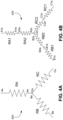
- FIG. 4A shows the coils 310-312 of the stator winding 300 in FIG. 3A connected in an exemplary star configuration 400.
- Coils 310-312 are represented as their resistive loads RA, RB and RC, respectively.
- the end point 'Ae' of coil 310, the end point 'Be' of coil 311, and the end point 'Ce' of coil 330 are connected together.
- each branch of the star configuration 400 comprises a single load corresponding to the coils for each phase in the stator winding 300.
- FIG. 4B shows an exemplary electrical connection of the coils in the stator winding 350, according to an embodiment of the present disclosure.
- coils 360-361 are represented as resistive loads RA1 and RA2 for phase A, respectively
- coils 362-363 are represented as resistive loads RB1 and RB2 for phase B, respectively
- coils 364-365 are represented as resistive loads RC1 and RC2 for phase C, respectively.
- coils 360-365 of stator winding 350 each comprise half the turns of coils 310-312 of stator winding 300.
- the resistive load per phase of the double stator winding 350 is the same as the resistive load per phase of the conventional stator winding 300, i.e.
- stator winding 350 does not place an additional resistive load on the electric motor when compared to the load presented by conventional stator winding 300.
- each branch of the star configuration 450 comprises two coils having their like terminals connected, i.e. the two coils are connected back to back.
- coils 360-361 represented by resistive loads RA1 and RA2, respectively, are connected such that the end points 'A1e' and 'A2e' are connected together.
- end points 'B1e' and 'B2e' of coils 362-363 of phase B represented by resistive loads RB1 and RB2, respectively are connected together
- end points 'C1e' and 'C2e' of coils 364-365 of phase C represented by resistive loads RC1 and RC2, respectively, are connected together.
- the start point 'A1s' of the resistive load RAT1 of coil 360 for phase A, the start point 'B1s' of the resistive load RB1 of coil 362 for phase B, and the start point 'C1s' of resistive load RC1 of coil 364 for phase C, are connected to a feed line, such as feed lined 143, 144 of the blood pump 100 in FIG. 1 . Additionally, the start point 'A2s' of the resistive load RA2 of coil 361 for phase A, the start point 'B2s' of the resistive load RB2 of coil 363 for phase B, and the start point 'C2s' of resistive load RC2 of coil 365 for phase C, are connected together.
- the manner in which the coils 360-365 of the double stator winding 350 of the present disclosure are connected is important as it determines how the coils 360-365 interact with the magnetic flux generated by the rotor during operation of the electric motor.
- the direction of current flowing through coil A1 of stator winding 350 is opposite to the direction of current flowing through coil A2.
- the direction of current flowing through coil B1 of stator winding 350 is opposite to the direction of current flowing through coil B2
- the direction of current flowing through coil C1 of stator winding 350 is opposite to the direction of current flowing through coil C2.
- coil A1 having a first direction of current flowing therethrough interacts with a first pole of the rotor while coil A2 having a second direction of current flowing therethrough, opposite to the first direction of current in coil A1, interacts with a second pole of the rotor opposite the first pole.
- coil B1 having a first direction of current flowing therethrough interacts with a first pole of the rotor while coil B2 having a second direction of current flowing therethrough, opposite to the first direction of current in coil B1, interacts with a second pole of the rotor opposite the first pole.
- coil C1 having a first direction of current flowing therethrough interacts with a first pole of the rotor while coil C2 having a second direction of current flowing therethrough, opposite to the first direction of current in coil C1, interacts with a second pole of the rotor opposite the first pole.
- the interaction of the coils of the stator winding 350 with the magnetic flux of the rotor during operation will be described in relation to FIG. 5 .
- FIG. 5 illustrates an exemplary cross-section 500 of the blood pump 100 of FIG. 1 employing stator winding 350 in a three-phase two-pole electric motor, taken along line X-X' during operation.
- stator winding 350 is suitable for the operation of a three-phase electric motor having two coils per phase per magnet pole pair
- a stator winding for an electric motor having any number of phases n and magnet pole pairs p can be used within the scope of the present disclosure, bringing the total number of coils used to 2np.
- coils marked with an 'x' indicate current flowing into the page, orthogonal to the plane of the page, while coils marked with a '•' indicate current flowing out of the page, orthogonal to the plane of the page.
- coils 360-361 for phase A are connected as described in relation to FIG. 4B such that the direction of current flowing through coil 360 is opposite to the direction of current flowing through coil 361.
- the polarity of the magnetic field generated from the permanent magnet stator 150 that coil 360 interacts with is opposite to that which interacts with coil 361.
- coils 362-363 for phase B of the electric motor are connected such that the direction of current flowing through coil 362 is opposite to the direction of current flowing through coil 363.
- the polarity of the magnetic field generated from the permanent magnet stator 150 that coil 362 interacts with is opposite to that which interacts with coil 363.
- coils 364-365 for phase C of the electric motor are connected such that the direction of current flowing through coil 362 is opposite to the direction of current flowing through coil 363.
- coils 364-365 each see a different polarity from the magnet pole pair of the stator.
- the polarity of the magnetic field generated from the permanent magnet stator 150 that coil 364 interacts with is opposite to that which interacts with coil 365.
- the interaction of the coils of the stator winding 350 with the magnetic flux of the rotor during operation generates a torque that acts on the rotor causing it to rotate.
- FIG. 6 illustrates another example of a cross-section of a double coil stator winding 600 for use in an electric motor having three phases A, B and C, and two permanent magnet pole pairs N1-S1 and N2-S2, according to an embodiment of the present disclosure.
- stator winding 600 also comprises two coils per phase per magnet pole pair resulting in 12 coils 610-621 in total.
- each phase A, B and C of the three-phase electric motor comprises two coils.
- phase A comprises coils 610-613 (labelled 'A1,' 'A2,' 'A3' and 'A4' respectively)
- phase B comprises coils 614-617 (labelled 'B1," 'B2,' 'B3' and 'B4' respectively)
- phase C comprises coils 618-621 (labelled "C1,” 'C2,' 'C3' and 'C4' respectively).
- FIG. 7 illustrates a further example of a cross-section of a double coil stator winding 700 for use in an electric motor having five phases A, B, C, D and E, and one permanent magnet pole pair N-S, according to an embodiment of the present disclosure.
- stator winding 700 also comprises two coils per phase per magnet pole pair resulting in 10 coils 710-719 in total.
- Phase A comprises coils 710-711 (labelled 'A1' and 'A2' respectively), phase B comprises coils 712-713 (labelled 'B1' and 'B2' respectively), phase C comprises coils 714-715 (labelled 'C1' and 'C2' respectively), phase D comprises coils 716-717 (labelled 'D1' and 'D2' respectively), and phase E comprises coils 718-719 (labelled 'E1' and 'E2' respectively). As shown in FIG.
- coil A1 having a first direction of current flowing therethrough interacts with a first pole N of the rotor
- coil A2 having a second direction of current flowing therethrough, opposite to the first direction of current in coil A1 interacts with a second pole S of the rotor opposite the first pole N
- coil B1 having a first direction of current flowing therethrough interacts with a first pole N of the rotor
- coil B2 having a second direction of current flowing therethrough, opposite to the first direction of current in coil B1 interacts with a second pole S of the rotor opposite the first pole N.
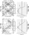
- each band representing coils 310-312 comprises a plurality of wires, only nine representative wires are shown per coil in FIGS. 8A-8D .
- Wire ends or lead lines 320-325 for each of the coils 310-312 are also shown at the proximal end of the stator winding 300.
- the direction shown on each lead line 320-325 represents the direction of winding the wires forming the respective coils 310-312.
- the direction indicated on lead line 320 represents the starting point of the wire forming winding 310 and lead line 321 indicates the end point of the wire forming winding 310.
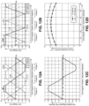
- FIG. 12C illustrates the variation in magnetic flux density B about the angular position of the stator winding for the electric motor having one magnetic pole pair, at an instant in time.
- the magnetic flux density curve of FIG. 12C would be of the same shape but would move along the horizontal axis as the north and south poles rotate about the longitudinal axis 105 of the rotor 150.
Landscapes
- Health & Medical Sciences (AREA)
- Engineering & Computer Science (AREA)
- Heart & Thoracic Surgery (AREA)
- Cardiology (AREA)
- Veterinary Medicine (AREA)
- General Health & Medical Sciences (AREA)
- Public Health (AREA)
- Mechanical Engineering (AREA)
- Anesthesiology (AREA)
- Biomedical Technology (AREA)
- Hematology (AREA)
- Life Sciences & Earth Sciences (AREA)
- Animal Behavior & Ethology (AREA)
- Power Engineering (AREA)
- Vascular Medicine (AREA)
- Transplantation (AREA)
- Windings For Motors And Generators (AREA)
- External Artificial Organs (AREA)
- Permanent Magnet Type Synchronous Machine (AREA)
- Insulation, Fastening Of Motor, Generator Windings (AREA)
- Structures Of Non-Positive Displacement Pumps (AREA)
Applications Claiming Priority (3)
| Application Number | Priority Date | Filing Date | Title |
|---|---|---|---|
| US201962853999P | 2019-05-29 | 2019-05-29 | |
| PCT/US2020/033990 WO2020242881A1 (fr) | 2019-05-29 | 2020-05-21 | Motif d'enroulement de bobine pour améliorer l'efficacité d'un moteur |
| EP20731356.0A EP3976129B1 (fr) | 2019-05-29 | 2020-05-21 | Motif d'enroulement de bobine pour améliorer l'efficacité d'un moteur |
Related Parent Applications (1)
| Application Number | Title | Priority Date | Filing Date |
|---|---|---|---|
| EP20731356.0A Division EP3976129B1 (fr) | 2019-05-29 | 2020-05-21 | Motif d'enroulement de bobine pour améliorer l'efficacité d'un moteur |
Publications (2)
| Publication Number | Publication Date |
|---|---|
| EP4576516A2 true EP4576516A2 (fr) | 2025-06-25 |
| EP4576516A3 EP4576516A3 (fr) | 2025-08-06 |
Family
ID=71016712
Family Applications (2)
| Application Number | Title | Priority Date | Filing Date |
|---|---|---|---|
| EP25174836.4A Pending EP4576516A3 (fr) | 2019-05-29 | 2020-05-21 | Motif d'enroulement de bobine pour une efficacité de moteur améliorée |
| EP20731356.0A Active EP3976129B1 (fr) | 2019-05-29 | 2020-05-21 | Motif d'enroulement de bobine pour améliorer l'efficacité d'un moteur |
Family Applications After (1)
| Application Number | Title | Priority Date | Filing Date |
|---|---|---|---|
| EP20731356.0A Active EP3976129B1 (fr) | 2019-05-29 | 2020-05-21 | Motif d'enroulement de bobine pour améliorer l'efficacité d'un moteur |
Country Status (11)
| Country | Link |
|---|---|
| US (2) | US11951298B2 (fr) |
| EP (2) | EP4576516A3 (fr) |
| JP (2) | JP7627233B2 (fr) |
| KR (1) | KR20220016121A (fr) |
| CN (3) | CN113891738A (fr) |
| CA (1) | CA3138273A1 (fr) |
| DK (1) | DK3976129T3 (fr) |
| ES (1) | ES3034013T3 (fr) |
| IL (2) | IL288308B2 (fr) |
| SG (1) | SG11202112285SA (fr) |
| WO (1) | WO2020242881A1 (fr) |
Families Citing this family (21)
| Publication number | Priority date | Publication date | Assignee | Title |
|---|---|---|---|---|
| EP3222301B1 (fr) * | 2016-03-23 | 2018-05-09 | Abiomed Europe GmbH | Pompe sanguine |
| DE102018201030B4 (de) | 2018-01-24 | 2025-10-16 | Kardion Gmbh | Magnetkuppelelement mit magnetischer Lagerungsfunktion |
| DE102018207611A1 (de) | 2018-05-16 | 2019-11-21 | Kardion Gmbh | Rotorlagerungssystem |
| DE102018207594A1 (de) | 2018-05-16 | 2019-11-21 | Kardion Gmbh | Rotor, Magnetkupplungsvorrichtung, Elektromotor für ein Herzunterstützungssystem, Pumpeneinheit für ein Herzunterstützungssystem sowie Verfahren zum Herstellen eines Rotors |
| DE102018207575A1 (de) | 2018-05-16 | 2019-11-21 | Kardion Gmbh | Magnetische Stirndreh-Kupplung zur Übertragung von Drehmomenten |
| DE102018208550A1 (de) | 2018-05-30 | 2019-12-05 | Kardion Gmbh | Leitungsvorrichtung zum Leiten eines Blutstroms für ein Herzunterstützungssystem, Herzunterstützungssystem und Verfahren zum Herstellen einer Leitungsvorrichtung |
| DE102018208538A1 (de) | 2018-05-30 | 2019-12-05 | Kardion Gmbh | Intravasale Blutpumpe und Verfahren zur Herstellung von elektrischen Leiterbahnen |
| DE102018208541A1 (de) | 2018-05-30 | 2019-12-05 | Kardion Gmbh | Axialpumpe für ein Herzunterstützungssystem und Verfahren zum Herstellen einer Axialpumpe für ein Herzunterstützungssystem |
| DE102018208549A1 (de) | 2018-05-30 | 2019-12-05 | Kardion Gmbh | Elektronikmodul für ein Herzunterstützungssystem und Verfahren zum Herstellen eines Elektronikmoduls für ein Herzunterstützungssystem |
| DE102018208539A1 (de) | 2018-05-30 | 2019-12-05 | Kardion Gmbh | Motorgehäusemodul zum Abdichten eines Motorraums eines Motors eines Herzunterstützungssystems und Herzunterstützungssystem und Verfahren zum Montieren eines Herzunterstützungssystems |
| DE102018210058A1 (de) | 2018-06-21 | 2019-12-24 | Kardion Gmbh | Statorschaufelvorrichtung zur Strömungsführung eines aus einer Austrittsöffnung eines Herzunterstützungssystems ausströmenden Fluids, Herzunterstützungssystem mit Statorschaufelvorrichtung, Verfahren zum Betreiben einer Statorschaufelvorrichtung und Herstellverfahren |
| DE102018210076A1 (de) | 2018-06-21 | 2019-12-24 | Kardion Gmbh | Verfahren und Vorrichtung zum Erkennen eines Verschleißzustands eines Herzunterstützungssystems, Verfahren und Vorrichtung zum Betreiben eines Herzunterstützungssystems und Herzunterstützungssystem |
| DE102018211297A1 (de) | 2018-07-09 | 2020-01-09 | Kardion Gmbh | Herzunterstützungssystem und Verfahren zur Überwachung der Integrität einer Haltestruktur eines Herzunterstützungssystems |
| DE102018211327A1 (de) | 2018-07-10 | 2020-01-16 | Kardion Gmbh | Laufrad für ein implantierbares, vaskuläres Unterstützungssystem |
| DE102018211328A1 (de) | 2018-07-10 | 2020-01-16 | Kardion Gmbh | Laufradgehäuse für ein implantierbares, vaskuläres Unterstützungssystem |
| DE102018212153A1 (de) | 2018-07-20 | 2020-01-23 | Kardion Gmbh | Zulaufleitung für eine Pumpeneinheit eines Herzunterstützungssystems, Herzunterstützungssystem und Verfahren zum Herstellen einer Zulaufleitung für eine Pumpeneinheit eines Herzunterstützungssystems |
| AU2019320533B2 (en) | 2018-08-07 | 2024-11-21 | Kardion Gmbh | Bearing device for a cardiac support system, and method for flushing an intermediate space in a bearing device for a cardiac support system |
| DE102020102474A1 (de) | 2020-01-31 | 2021-08-05 | Kardion Gmbh | Pumpe zum Fördern eines Fluids und Verfahren zum Herstellen einer Pumpe |
| CA3192451A1 (fr) | 2020-09-14 | 2022-03-17 | Johannes Bette | Pompe de support cardiovasculaire dotee d'un impulseur a zone d'ecoulement variable |
| JP2023550938A (ja) | 2020-11-20 | 2023-12-06 | カルディオン ゲーエムベーハー | ガイドワイヤ補助具付き機械的循環支持システム |
| CN115445078A (zh) * | 2022-08-28 | 2022-12-09 | 上海炫脉医疗科技有限公司 | 一种微型血泵及制造方法 |
Family Cites Families (12)
| Publication number | Priority date | Publication date | Assignee | Title |
|---|---|---|---|---|
| US5197180A (en) | 1991-09-13 | 1993-03-30 | Faraday Energy Foundation | Method for making an electric motor winding |
| DE29821564U1 (de) * | 1998-12-02 | 2000-07-13 | Impella Cardiotechnik AG, 52074 Aachen | Fluidgekühlter Elektromotor mit hoher Leistungsdichte |
| DE29921352U1 (de) | 1999-12-04 | 2001-04-12 | Impella Cardiotechnik AG, 52074 Aachen | Intravasale Blutpumpe |
| JP5284979B2 (ja) * | 2006-12-28 | 2013-09-11 | レスメド・モーター・テクノロジーズ・インコーポレーテッド | モーター内のスロットレスステータ用のコイル巻き付け方法及び構造 |
| ES2423801T3 (es) * | 2010-12-15 | 2013-09-24 | Infranor Holding S.A. | Motor síncrono con imanes permanentes |
| US9421311B2 (en) * | 2012-07-03 | 2016-08-23 | Thoratec Corporation | Motor assembly for catheter pump |
| US9979247B2 (en) | 2014-11-06 | 2018-05-22 | Medtronic Xomed, Inc. | Surgical instrument motor with increased number of wires per phase set and increased fill factor and corresponding manufacturing method |
| WO2016130944A1 (fr) * | 2015-02-12 | 2016-08-18 | Thoratec Corporation | Système et procédé de commande de la position d'un rotor en lévitation |
| DE102016220040A1 (de) * | 2016-10-14 | 2018-04-19 | Siemens Aktiengesellschaft | Helixartige Wicklung mit homogenerer Feldausnutzung |
| WO2018139245A1 (fr) * | 2017-01-30 | 2018-08-02 | 合同会社IP Bridge1号 | Dispositif électromécanique sans noyau, conducteur pour bobine et procédé de production de dispositif électromécanique sans noyau |
| CN107104570A (zh) * | 2017-07-03 | 2017-08-29 | 中国医学科学院阜外医院 | 一种用于植入式轴流血泵的无槽电机 |
| EP3456367A1 (fr) | 2017-09-19 | 2019-03-20 | Abiomed Europe GmbH | Pompe sanguine |
-
2020
- 2020-05-21 EP EP25174836.4A patent/EP4576516A3/fr active Pending
- 2020-05-21 SG SG11202112285SA patent/SG11202112285SA/en unknown
- 2020-05-21 DK DK20731356.0T patent/DK3976129T3/da active
- 2020-05-21 WO PCT/US2020/033990 patent/WO2020242881A1/fr not_active Ceased
- 2020-05-21 CN CN202080039396.4A patent/CN113891738A/zh active Pending
- 2020-05-21 KR KR1020217041955A patent/KR20220016121A/ko active Pending
- 2020-05-21 US US16/880,043 patent/US11951298B2/en active Active
- 2020-05-21 JP JP2021570294A patent/JP7627233B2/ja active Active
- 2020-05-21 IL IL288308A patent/IL288308B2/en unknown
- 2020-05-21 CN CN202311655012.3A patent/CN117679626A/zh active Pending
- 2020-05-21 ES ES20731356T patent/ES3034013T3/es active Active
- 2020-05-21 CA CA3138273A patent/CA3138273A1/fr active Pending
- 2020-05-21 EP EP20731356.0A patent/EP3976129B1/fr active Active
- 2020-05-21 CN CN202311755342.XA patent/CN117717701A/zh active Pending
-
2024
- 2024-03-07 US US18/598,327 patent/US20240316336A1/en active Pending
-
2025
- 2025-01-24 JP JP2025010514A patent/JP2025076437A/ja active Pending
- 2025-09-14 IL IL323355A patent/IL323355A/en unknown
Also Published As
| Publication number | Publication date |
|---|---|
| CN113891738A (zh) | 2022-01-04 |
| AU2020283518A1 (en) | 2022-02-10 |
| DK3976129T3 (da) | 2025-06-30 |
| IL288308B2 (en) | 2026-02-01 |
| US11951298B2 (en) | 2024-04-09 |
| IL288308B1 (en) | 2025-10-01 |
| KR20220016121A (ko) | 2022-02-08 |
| JP2022535209A (ja) | 2022-08-05 |
| IL323355A (en) | 2025-11-01 |
| ES3034013T3 (en) | 2025-08-12 |
| EP3976129B1 (fr) | 2025-05-14 |
| US20200376181A1 (en) | 2020-12-03 |
| JP2025076437A (ja) | 2025-05-15 |
| EP4576516A3 (fr) | 2025-08-06 |
| JP7627233B2 (ja) | 2025-02-05 |
| US20240316336A1 (en) | 2024-09-26 |
| CA3138273A1 (fr) | 2020-12-03 |
| SG11202112285SA (en) | 2021-12-30 |
| EP3976129A1 (fr) | 2022-04-06 |
| IL288308A (en) | 2022-01-01 |
| CN117679626A (zh) | 2024-03-12 |
| WO2020242881A1 (fr) | 2020-12-03 |
| CN117717701A (zh) | 2024-03-19 |
Similar Documents
| Publication | Publication Date | Title |
|---|---|---|
| EP3976129B1 (fr) | Motif d'enroulement de bobine pour améliorer l'efficacité d'un moteur | |
| US12011583B2 (en) | Intravascular blood pump having multilayer coreless coils | |
| JP2025076437A5 (fr) | ||
| CN107078579A (zh) | 气隙式绕组 | |
| AU2020283518B2 (en) | Coil winding pattern for enhanced motor efficiency | |
| HK40068879B (en) | Coil winding pattern for enhanced motor efficiency | |
| HK40068879A (en) | Coil winding pattern for enhanced motor efficiency | |
| HK40070450B (en) | Intravascular blood pump having multilayer coreless coils | |
| HK40070450A (en) | Intravascular blood pump having multilayer coreless coils |
Legal Events
| Date | Code | Title | Description |
|---|---|---|---|
| PUAI | Public reference made under article 153(3) epc to a published international application that has entered the european phase |
Free format text: ORIGINAL CODE: 0009012 |
|
| STAA | Information on the status of an ep patent application or granted ep patent |
Free format text: STATUS: THE APPLICATION HAS BEEN PUBLISHED |
|
| AC | Divisional application: reference to earlier application |
Ref document number: 3976129 Country of ref document: EP Kind code of ref document: P |
|
| AK | Designated contracting states |
Kind code of ref document: A2 Designated state(s): AL AT BE BG CH CY CZ DE DK EE ES FI FR GB GR HR HU IE IS IT LI LT LU LV MC MK MT NL NO PL PT RO RS SE SI SK SM TR |
|
| REG | Reference to a national code |
Ref country code: DE Ref legal event code: R079 Free format text: PREVIOUS MAIN CLASS: H02K0007140000 Ipc: A61M0060130000 |
|
| PUAL | Search report despatched |
Free format text: ORIGINAL CODE: 0009013 |
|
| AK | Designated contracting states |
Kind code of ref document: A3 Designated state(s): AL AT BE BG CH CY CZ DE DK EE ES FI FR GB GR HR HU IE IS IT LI LT LU LV MC MK MT NL NO PL PT RO RS SE SI SK SM TR |
|
| RIC1 | Information provided on ipc code assigned before grant |
Ipc: A61M 60/13 20210101AFI20250627BHEP Ipc: A61M 60/237 20210101ALI20250627BHEP Ipc: A61M 60/416 20210101ALI20250627BHEP Ipc: A61M 60/422 20210101ALI20250627BHEP Ipc: H02K 1/27 20220101ALI20250627BHEP Ipc: H02K 3/28 20060101ALI20250627BHEP Ipc: H02K 3/47 20060101ALI20250627BHEP Ipc: H02K 7/14 20060101ALI20250627BHEP Ipc: H02K 1/278 20220101ALI20250627BHEP |
|
| P01 | Opt-out of the competence of the unified patent court (upc) registered |
Free format text: CASE NUMBER: UPC_APP_5521_4576516/2025 Effective date: 20250901 |
|
| STAA | Information on the status of an ep patent application or granted ep patent |
Free format text: STATUS: REQUEST FOR EXAMINATION WAS MADE |
|
| 17P | Request for examination filed |
Effective date: 20260205 |