EP4576616A1 - Systèmes et procédés pour estimer une matrice d'auto-corrélation pour un émetteur-récepteur - Google Patents
Systèmes et procédés pour estimer une matrice d'auto-corrélation pour un émetteur-récepteur Download PDFInfo
- Publication number
- EP4576616A1 EP4576616A1 EP24203130.0A EP24203130A EP4576616A1 EP 4576616 A1 EP4576616 A1 EP 4576616A1 EP 24203130 A EP24203130 A EP 24203130A EP 4576616 A1 EP4576616 A1 EP 4576616A1
- Authority
- EP
- European Patent Office
- Prior art keywords
- antenna
- power
- antennas
- combined
- unique pair
- Prior art date
- Legal status (The legal status is an assumption and is not a legal conclusion. Google has not performed a legal analysis and makes no representation as to the accuracy of the status listed.)
- Pending
Links
Images


Classifications
-
- H—ELECTRICITY
- H04—ELECTRIC COMMUNICATION TECHNIQUE
- H04B—TRANSMISSION
- H04B17/00—Monitoring; Testing
- H04B17/20—Monitoring; Testing of receivers
- H04B17/21—Monitoring; Testing of receivers for calibration; for correcting measurements
-
- H—ELECTRICITY
- H01—ELECTRIC ELEMENTS
- H01Q—ANTENNAS, i.e. RADIO AERIALS
- H01Q3/00—Arrangements for changing or varying the orientation or the shape of the directional pattern of the waves radiated from an antenna or antenna system
- H01Q3/26—Arrangements for changing or varying the orientation or the shape of the directional pattern of the waves radiated from an antenna or antenna system varying the relative phase or relative amplitude of energisation between two or more active radiating elements; varying the distribution of energy across a radiating aperture
- H01Q3/267—Phased-array testing or checking devices
-
- H—ELECTRICITY
- H04—ELECTRIC COMMUNICATION TECHNIQUE
- H04B—TRANSMISSION
- H04B17/00—Monitoring; Testing
- H04B17/20—Monitoring; Testing of receivers
- H04B17/201—Monitoring; Testing of receivers for measurement of specific parameters of the receiver or components thereof
- H04B17/202—Power received at the antenna
Definitions
- the invention relates generally to transceivers, and in particular to estimating an auto-correlation matrix for a transceiver.
- An auto-correlation matrix is used for many applications associated with phased-array antenna systems. Such applications may include, but are not limited to, beamformer steering, interference mitigation (e.g., one or a plurality of jammers), multi-path mitigation, identifying locations of signal sources, Multiple-Signal-Classification (MUSIC), Estimation of Signal Parameters via Rotational Invariance Techniques (ESPRIT), Time-difference of arrival (TDOA), etc. Therefore, accurately and efficiently estimating the autocorrelation matrix is important as it affects the system's ability to effectively implement the above-described applications.
- beamformer steering interference mitigation (e.g., one or a plurality of jammers), multi-path mitigation, identifying locations of signal sources, Multiple-Signal-Classification (MUSIC), Estimation of Signal Parameters via Rotational Invariance Techniques (ESPRIT), Time-difference of arrival (TDOA), etc. Therefore, accurately and efficiently estimating the autocorrelation matrix is important as it affects the system's ability
- the transceiver may be coupled to a multi-antenna array that includes a plurality of antennas. Each antenna may receive signals (RF signals).
- the transceiver may implement one or more functions based on the received signals, wherein the functions require the use of an auto-correlation matrix.
- the one or more embodiments as described herein may utilize power measurements obtained in the RF domain to estimate the correlation matrix more efficiently and less expensively than conventional systems and techniques.
- the one or more power sensors i.e., one or more combined power sensors, for each unique pair of antennas may measure a combined power of each of the shifted signals and the signal received at the other antenna of the unique pair of antennas.
- a plurality e.g., three
- the transceiver may optionally include an amplitude corrector and/or an RF power combiner.
- the amplitude corrector may correct the amplitude of each shifted signal to generate a plurality (e.g., three) of corrected signals.
- the shifted signals may be corrected in amplitude in a variety of different ways to generate the plurality of corrected signals.
- Each corrected signal and the signal from the other antenna of the unique pair may be combined by a corresponding RF power combiner to generate a plurality (e.g., three) of combined signals.
- the one or more power sensors i.e., one or more combined power sensors, for each unique pair of antennas may measure the combined power of the plurality (e.g., three) of combined signals output from the RF power combiner. Therefore, and in this embodiment with an amplitude corrector and/or RF combiner, a plurality (e.g., three) of combined power measurements are also made for each unique pair of antennas of the multi-antenna array.
- the transceiver may include a module (e.g., a correlation module) that is executed by a processor of the transceiver.
- the module may use the plurality (e.g., three) of power measurements for each unique pair of antennas to solve a system of power equations to calculate three unknowns that relate to the characteristics of the corresponding unique pair of antennas.
- the module may use the three unknowns for each unique pair of antennas to calculate a maximum power and a minimum power for the corresponding unique pair of antennas.
- the module may use a search technique (e.g., maximum and/or minimum search technique) to identify the maximum and minimum powers, for the corresponding unique pair of antennas, from the plurality of combined power measurements taken for the corresponding unique pair of antennas at a plurality of different phase offsets that are based on a selected offset interval.
- a search technique e.g., maximum and/or minimum search technique
- the module may use the maximum power and the minimum power for each unique pair of antennas to estimate an auto-correlation for the corresponding unique pair of antennas.
- the module may then estimate the auto-correlation matrix for the multi-antenna array using the auto-correlation estimated for each unique pair of antennas and the power measured for each antenna of the multi-antenna array.
- the transceiver may implement a function using the auto-correlation matrix estimated according to the one or more embodiments as described herein.
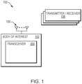
- Fig. 1 is an illustration of an example system environment for estimating an auto-correlation matrix for a transceiver according to the one or more embodiments as described herein.
- System environment 100 includes transceiver 200 with a coupled multi-antenna array 106.
- the ellipsis between the two antennas of the multi-antenna array 106 is used to indicate that multi-antenna array 106 may include any number of a plurality of antennas.
- Each of the plurality of antennas of multi-antenna array 106 may be configured to transmit and/or receive one or more signals to/from one or more transmitters/receivers 108.
- multi-antenna array, phase-array antenna, antenna array, antenna array system, etc. may be used interchangeably, and each is meant to indicate a system that includes at least multi-antenna array 106 with a plurality of antennas.
- the one or more transmitters/receivers 108 may be one or more Global Navigation Satellite System (GNSS) satellites that transmit one or more navigation signals, e.g., GNSS satellite signals (not shown).
- GNSS Global Navigation Satellite System
- transmitters/receivers 108 may be GNSS satellites transmitting GNSS satellite signals, it is expressly contemplated that the one or more embodiments as described herein may be utilized with any of a variety of different types of transmitters/receivers 108.
- transmitters/receivers 108 may be terrestrial transmitters/receivers that transmit and/or receive any of a variety of different signals such as, but not limited to, navigation signals.
- the description of transmitters/receivers 108 being GNSS satellites that transmit GNSS signals should be taken for illustrative purposes only.
- transceiver 200 may be a navigation receiver.
- the navigation receiver may, based on the reception of signals at multi-antenna array 106, produce raw measurements (e.g., GNSS raw measurements), such as pseudoranges, carrier phases (e.g., differenced carrier phase measurements), and Doppler velocities; position (e.g., GNSS position), velocity (e.g., GNSS velocity), attitude, and time (e.g., GNSS time), position covariance, time covariance, and velocity covariance; and, as appropriate, GNSS observables.
- raw measurements e.g., GNSS raw measurements
- pseudoranges e.g., carrier phases (e.g., differenced carrier phase measurements)
- Doppler velocities e.g., GNSS position
- velocity e.g., GNSS velocity
- attitude e.g., GNSS time
- time e.g., GNSS time
- Transceiver 200 may implement one or more functions that require the use of an auto-correlation matrix. Such functions may include, but are not limited to, beamformer steering, interferer mitigation steering (e.g., one or a plurality of jammers), multipath mitigation, identifying locations of signal sources, Multiple-Signal-Classification (MUSIC), Estimation of Signal Parameters via Rotational Invariance Techniques (ESPRIT), Time-difference of arrival (TDOA), etc.
- beamformer steering e.g., interferer mitigation steering (e.g., one or a plurality of jammers)
- MUSIC Multiple-Signal-Classification
- ESPRIT Estimation of Signal Parameters via Rotational Invariance Techniques
- TDOA Time-difference of arrival
- a module e.g., correlation module 214 in Figs. 2A-2C
- RF radio frequency
- the auto-correlation matrix can be estimated in the RF domain and directly from the signals received at the multi-antenna array 106 as will be described in further detail below, the signals do not need to be demodulated (no heterodyne converters required), digitized (no high speed ADCs required), or processed at baseband speeds (no FPGAs required) as is required by conventional systems and techniques.
- the one or more embodiments as described herein for estimating an auto-correlation matrix for a transceiver is more efficient and less expensive (e.g., in terms of processing hardware, power, and cost) when compared to conventional systems and techniques.
- the one or more embodiments as described herein provide an improvement in the existing technological field of transceiver device operation.
- the one or more embodiments as described herein can estimate the auto-correlation matrix in a manner that is more efficient and less expensive when compared to conventional systems and techniques.
- the one or more embodiments as described herein provide an improvement in the existing technological field for transceiver devices that require the use of an auto-correlation matrix for implementing one or more transceiver functions (e.g., beamformer steering, interference mitigation steering, identifying locations of signal sources, MUSIC, ESPRIT, TDOA, etc.).
- an auto-correlation matrix for implementing one or more transceiver functions (e.g., beamformer steering, interference mitigation steering, identifying locations of signal sources, MUSIC, ESPRIT, TDOA, etc.).
- Fig. 2A is an example transceiver 200A with a multi-antenna array 106A, having three antennas, for estimating an auto-correlation matrix according to the one or more embodiments as described herein.
- multi-antenna array 106A includes antennas 201A, 201B, and 201C.
- a dashed box is provided around each of antennas 201A, 201B, and 201C to indicate that any line from a dashed box represents a path from the corresponding antenna to a power sensor or a phase shifter in Fig. 2A .
- Each of the paths in Fig. 2A which may be indicated with an arrow, may be a cable, wire, or some other type of connection.
- each of the power sensors in Fig. 2A may measure, i.e., determine, power.
- each phase shifter may, based on a phase offset, shift signals that are received at an antenna in phase and in amplitude.
- the signals received at antennas 201A, 201B, and 201C may be RF signals, i.e., signals in the RF domain.
- antennas 201A, 201B, and 201C may receive signals from transmitters/receivers 108 of Fig. 1 .
- the signals may be navigation signals.
- transceiver 200A includes a separate and dedicated power sensor for each of antennas 201A, 201B, and 201C.
- power sensor 202A may correspond to antenna 201A and may measure the power of the signals (e.g., RF signals) received at antenna 201A.
- Power sensor 202B may correspond to antenna 201B and may measure the power of the signals (e.g., RF signals) received at antenna 201B.
- Power sensor 202C may correspond to antenna 201C and may measure the power of the signals (e.g., RF signals) received at antenna 201C.
- the powers measured at power sensors 202A-202C may be provided to correlation module 214 as depicted in Fig. 2A .
- each of power sensors 202A-202C may be referred to as an antenna assigned power sensor.
- transceiver 200A also includes a different power sensor and a different phase shifter for each unique pair of antennas of multi-antenna array 106A.
- the unique pairs of antennas include (1) antenna 201A and antenna 201B, (2) antenna 201B and antenna 201C, and (3) antenna 201A and 201C.
- transceiver 200A includes phase shifter 204A and power sensor 203A for the unique pair of antennas 201A and 201B.
- Phase shifter 204A shifts the signals that are received at antenna 201B in phase and in amplitude to generate shifted signals.
- Power sensor 203A may then measure a combined power of a shifted signal, corresponding to the signals received at antenna 201B, and a signal received at antenna 201A as depicted in Fig. 2A .
- Transceiver 200A further includes phase shifter 204B and power sensor 203B for the unique pair of antennas 201B and 201C.
- Phase shifter 204B shifts the signals that are received at antenna 201C in phase and in amplitude to generate shifted signals.
- Power sensor 203B may then measure a combined power of a shifted signal, corresponding to the signals received at antenna 201C, and a signal received at antenna 201B as depicted in Fig. 2A .
- Transceiver 200A also includes phase shifter 204C and power sensor 203C for the unique pair of antennas 201A and 201C.
- Phase shifter 204C shifts the signals that are received at antenna 201A in phase and in amplitude to generate shifted signals.
- Power sensor 203C may then measure a combined power of a shifted signal, corresponding to the signals received at antenna 201A, and a signal received at antenna 201C as depicted in Fig. 2A .
- each of power sensors 203A-203C may be referred to as a combined power sensor.
- each of phase shifters 204A, 204B, and 204C may have a plurality of different phase settings.
- the phase settings may be a plurality of different phase offsets at a predetermined/selected phase interval.
- the plurality of different phase settings are three phase settings of 0, ⁇ /2, and ⁇ (radians).
- each of power sensors 203A, 203B, and 203C may make a plurality (e.g., three) of combined power measurements for each unique pair of antennas in the manner described above and based on the plurality (e.g., three) of different phase settings.
- the correlation module 214 may provide a signal to each of phase shifters 204A, 204B, and 204C to modify the phase settings of the phase shifters between the plurality of different values (e.g., 0, ⁇ /2, and ⁇ (radians)).
- the signals from the correlation module 214 to the phase shifters 204A, 204B, and 204C are indicated in Fig. 2A with dashed arrows.
- phase shifter 204A is coupled to antenna 201B for the unique pair of antennas 201A and 201B, it is expressly contemplated that the phase shifter 204A can instead be coupled to antenna 201A for the unique pair of antennas 201A and 201B.
- the unique pair of antennas 201A and 201C consider the unique pair of antennas 201A and 201C.
- phase shifter 204C may be coupled to antenna 201A, it is expressly contemplated that the phase shifter 204B, which is used for the unique pair of antennas 201B and 201C, may also be used for the unique pair of antennas 201A and 201C. Therefore, the output of the phase shifter 204B may be provided to both power sensors 203B and 203C.
- phase shifters as depicted in Fig. 2A is for illustrative purposes only, and it is expressly contemplated that the one or more embodiments as described herein may utilize any configuration such that the signals received at one antenna, of each unique pair of antennas, is shifted in phase and in amplitude.
- a transceiver 200 (e.g., transceiver 200A of Fig. 2A ) according to the one or more embodiments as described herein requires a number of power sensors that is equal to n+n(n-1) / 2, where n is the number of antennas of the multi-antenna array 106 (e.g., multi-antenna array 106A of Figs. 2A ).
- transceiver 200A includes three antennas. Therefore, transceiver 200A requires the use of six different power sensors, e.g., 3+3(3-1)/2. Specifically, transceiver 200A includes three different power sensors (e.g., 202A, 202B, and 202C), one for each of antennas 201A, 201B, and 201C. Further, transceiver 200A includes three additional power sensors (e.g., 203A, 203B, and 203C), one for each unique pair of antennas. Therefore, transceiver 200A of Fig. 2A includes a total of six power sensors according to the one or more embodiments as described herein.
- a transceiver 200 that includes a multi-antenna array 106 with two antennas would require a total of three power sensors, e.g., 2+2(2-1)/2. Specifically, a different power sensor would be required for each of the two antennas, and then a third power sensor would be required for the single unique pair of antennas.
- a transceiver 200 that includes a multi-antenna array 106 with six antennas would require a total of twenty-one power sensors, e.g., 6+6(6-1)/2. Specifically, a different power sensor would be required for each of the six antennas. Additionally, a different power sensor would also be required for the fifteen unique pairs of antennas.
- the multi-antenna array 106A of Fig. 2A including three antennas is for illustrative purposes only, and it is expressly contemplated that the one or more embodiments as described herein are applicable to a multi-antenna array 106 with any number of a plurality of antennas.
- correlation module 214 may implement the one or more embodiments as described herein. Specifically, and as will be described in further detail below with relation to the flow diagram of Figs. 3A and 3B , correlation module 214 may use the power measurements obtained by the six different power sensors to estimate an auto-correlation matrix for the transceiver 200A with multi-antenna array 106A.
- the correlation module 214 may utilize the power measurement from each of power sensors 202A-202C with the plurality (e.g., three) of different combined power measurements from power sensors 203A-203C to estimate an auto-correlation matrix for transceiver 200A with multi-antenna array 106A.
- Fig. 2B is a different example transceiver 200B with a multi-antenna array 106A having three antennas, amplitude correctors, and RF power combiners for estimating an auto-correlation matrix according to the one or more embodiments as described herein.
- Fig. 2B is similar to Fig. 2A in that the transceiver 200B of Fig. 2B includes a different power sensor for each individual antenna and a different power sensor for each unique pair of antennas. However, the transceiver 200B also includes an amplitude corrector and a power combiner for each phase shifter.
- each phase shifter e.g., 204A-204C
- the shifted signal that is output from the phase shifter may be provided to an amplitude corrector that may correct the amplitude of the shifted signal to generate a corrected shifted signal.
- the corrected shifted signal may then be provided to an RF power combiner with a signal from the other antenna of the unique pair of antennas to generate a combined signal.
- the combined signal may then be provided to a power sensor to measure a power of the combined signal.
- the shifted signal from phase shifter 204A (corresponding to the signals received at antenna 201B) may be provided to amplitude corrector 205B.
- the amplitude corrector 205B may correct the amplitude of the shifted signal and generate a corrected shifted signal.
- the corrected shifted signal may be provided to the RF power combiner 206B that may combine the corrected shifted signal with the signal from antenna 201A to generate a combined signal.
- the combined signal may then be provided to power sensor 203A to measure the power of the combined signal and the measured combined power may be provided to the correlation module 214.
- the amplitude corrector 205A and RF power combiner 206A may operate in a similar manner for the unique pair of antennas 201B and 201C. Further, the amplitude corrector 205C and RF power combiner 206C may operate in a similar manner for the unique pair of antennas 201A and 201C.
- the power measured from the six different power sensors of transceiver 200B are provided to correlation module 214 that can estimate an auto-correlation matrix for the transceiver 200B with multi-antenna array 106A.
- Fig. 2C is an even different example transceiver, for estimating an auto-correlation matrix, including a multi-antenna array with two antennas and without phase shifters of Figs. 2A and 2B and without amplitude correctors of Fig. 2B according to the one or more embodiments as described herein.
- the transceiver 200C of Fig. 2C includes multi-antenna array 106B with two antennas 201D and 201E for simplicity and ease of understanding.
- the configuration of the transceiver 200C of Fig. 2C is applicable to a transceiver with a multi-antenna array that includes any other number of a plurality of antennas.
- power sensor 202D measures the power of the RF signals received at antenna 201D.
- Power sensor 202E measures the power of the RF signals received at antenna 201E. The measured powers can then be provided to correlation module 214.
- the RF signals from one antenna of each unique pair of antennas is programmatically (e.g., simultaneously available in hardware) offset in phase (without a phase shifter), based on a phase setting of 0, ⁇ /2, and ⁇ (radians).
- the RF signals received at antenna 201D are offset in phase by 0, ⁇ /2, and ⁇ (radians) to generate three different shifted signals.
- Each of the three different shifted signals may be provided to a different RF power combiner to combine the corresponding shifted signal with the signals received at antenna 201E.
- RF power combiner 206D combines the shifted signals, corresponding to the signals received at antenna 201D with a phase offset of 0, with the RF signals received at antenna 201E to generate combined signals.
- RF power combiner 206E combines the shifted signals, corresponding to the signals received at antenna 201D with a phase offset of ⁇ /2, with the RF signals received at antenna 201E to generate combined signals.
- RF power combiner 206F combines the shifted signals, corresponding to the signals received at antenna 201D with a phase offset of ⁇ , with the RF signals received at antenna 201E to generate combined signals.
- Each of the three combined signals may be provided to a different power sensor to generate three different combined power measurements for unique pair of antennas 201D and 201E.
- power sensor 203D measures a power of the combined signal that is received from RF power combiner 206D and that is based on a phase offset of 0.
- Power sensor 203E measures a power of the combined signal that is received from RF power combiner 206E and that is based on a phase offset of ⁇ /2.
- Power sensor 203F measures a power of the combined signal that is received from RF power combiner 206F and that is based on a phase offset of ⁇ .
- the three different combined power measurements are then provided from power sensors 203D-203F to correlation module 214.
- the correlation module 214 can estimate the auto-correlation matrix for transceiver 200C using the three combined power measurements and the power measurements for each antenna of multi-antenna array 106B. Therefore, and based on the configuration of transceiver 200C, a total of five power sensors and five power measurements are needed for the correlation module 214 to estimate the auto-correlation matrix for the transceiver 200C of Fig. 2C . As such, a transceiver according to the one or more embodiments as described herein that does not include a phase shifter may require a total of 3 n +1 power sensors to estimate the auto-correlation matrix.
- Figs. 3A and 3B together constitute a flow diagram of a sequence of steps for estimating an auto-correlation matrix for a multi-antenna array using power measurements from a plurality of sensors according to the one or more embodiments as described herein.
- the flow diagram of Figs. 3A and 3B may refer to the transceivers 200A and 200B and the multi-antenna array 106A of Figs. 2A and 2B .
- the references to Figs. 2A and 2B are for illustrative purposes only, and the flow diagram of Figs. 3A and 3B are applicable to any antenna array system that requires the use of an auto-correlation matrix (e.g., transceiver 200C of Fig. 2C ).
- Figs. 3A and 3B include general formulas, for any unique pair of antennas, with a corresponding formula number. However, the formulas included in the description of Figs. 3A and 3B that are related to the specific examples of Figs. 2A and 2B do not include formula numbers.
- each antenna of the multi-antenna array 106 receives signals.
- each of antennas 201A, 201B, and 201C may receive signals.
- the signals may be RF signals received from transmitters/receivers 108.
- the signals may be navigation signals in the RF domain that are received from one or more transmitters/receivers 108.
- a different power sensor i.e., antenna assigned power sensor
- transceivers 200A and 200B include a separate and dedicated power sensor for each of antennas 201A, 201B, and 201C.
- power sensor 202A measures the power of the signals received at antenna 201A.
- power sensor 202B measures the power of the signals received at antenna 201B, while power sensor 202C measures the power of the signals received at antenna 201C.
- the unit of measurement for each of the measured power values may be watts or milliwatts.
- the powers measured at power sensors 202A-202C may be provided to correlation module 214 as depicted in Figs. 2A and 2B .
- a phase shifted signal with a first phase offset, is generated from the signals received at one antenna of each unique pair of antennas.
- the first phase offset is 0 (radians).
- the generated phase shifted signal is shifted in phase and in amplitude based on the first offset, e.g., phase offset of 0.
- first, second, and third are used herein to differentiate between the different phase offsets.
- transceivers 200A and 200B include phase shifter 204A for the unique pair of antennas 201A and 201B.
- Phase shifter 204A may, based on a phase setting of 0, shift the signals that are received at antenna 201B in phase and in amplitude to generate shifted signals.
- transceivers 200A and 200B may include phase shifter 204B for the unique pair of antennas 201B and 201C.
- Phase shifter 204B may, based on a phase setting of 0, shift the signals that are received at antenna 201C in phase and in amplitude to generate shifted signals.
- Transceivers 200A and 200B may also include phase shifter 204C for the unique pair of antennas 201A and 201C.
- Phase shifter 204C may, based on a phase setting of 0, shift the signals that are received at antenna 201A in phase and in amplitude to generate shifted signals.
- phase shifter e.g., 204A, 204B, and 204C
- a different phase shifter is utilized for each unique pair of antennas to shift the signals received at one antenna of the unique pair based on a first phase setting, e.g., a phase setting of 0.
- the phase shifted signal with a phase offset of 0 may be generated programmatically for antenna 201D of unique pair of antennas 201D and 201E.
- each of one or more power sensors measures the combined power of the combined signal that is based on the first phase offset, e.g., 0.
- transceiver 200A includes power sensor 203A, for unique pair of antennas 201A and 201B, that receives the signals from antenna 201A and receives the shifted signals from phase shifter 204A that may have a phase setting of 0 and that is coupled to antenna 201B.
- Power sensor 203A may measure the combined power of the received signals.
- Power sensor 203B of Fig. 2A may operate similarly for the unique pair of antennas 201B and 201C based on a phase setting of 0 for phase shifter 204B.
- Power sensor 203C of Fig. 2A may also operate similarly for the unique pair of antennas 201A and 201C based on a phase setting of 0 for phase shifter 204C.
- amplitude correctors and RF combiners may be utilized prior to a power sensor measuring the combined power for a unique pair of antennas.
- the shifted signal that is generated by phase shifter 204A for the unique pair of antennas 201A and 201B may be provided to amplitude corrector 205B.
- Amplitude corrector 205B may correct the amplitude of the shifted signal to generate a corrected shifted signal.
- the corrected shifted signal may then be provided to RF power combiner 206B that may combine the corrected shifted signal with the signal received at antenna 201A to generate a combined signal.
- the combined signal may then be provided to power sensor 203A that may measure a power of the combined signal for the unique pair of antennas 201A and 201B.
- Amplitude corrector 205A and RF power combiner 206A may operate similarly for unique pair of antennas 201B and 201C. Further, amplitude corrector 205C and RF power combiner 206C may operate similarly for unique pair of antennas 201A and 201C.
- RF power combiner 206D may be utilized, without an amplitude corrector, for unique pair of antennas 201D and 201E. Specifically, RF power combiner 206D may combine the programmatically shifted signals (based on a phase offset of 0) and the signals received at antenna 201E to generate combined signals. Power sensor 203D may measure the power of the combined signals based on a phase offset of 0.
- a phase shifted signal is generated from the signals received at one antenna of the unique pair of antennas.
- the second phase offset is ⁇ /2 (radians).
- the generated phase shifted signal is shifted in phase and in amplitude based on the second offset, e.g., phase offset of ⁇ /2.
- transceivers 200A and 200B include phase shifter 204A for the unique pair of antennas 201A and 201B.
- Phase shifter 204A may, based on a phase setting of ⁇ /2, shift the signals that are received at antenna 201B in phase and in amplitude to generate shifted signals.
- Phase shifter 204B may operate similarly for unique pair of antennas 201B and 201C using a phase setting of ⁇ /2.
- phase shifter 204C may operate similarly for unique pair of antennas 201A and 201C using a phase setting of ⁇ /2.
- the phase shifted signal with a phase offset of ⁇ /2 may be generated programmatically for antenna 201D of unique pair of antennas 201D and 201E.
- each of one or more power sensors measures the combined power of the combined signal that is based on the second phase offset, e.g., ⁇ /2.
- transceiver 200A includes power sensor 203A, for unique pair of antennas 201A and 201B, that receives the signal from antenna 201A and receives the shifted signal from phase shifter 204A that may have a phase setting of ⁇ /2 and that is coupled to antenna 201B.
- Power sensor 203A may measure the combined power of the received signals.
- Power sensor 203B may operate similarly for the unique pair of antennas 201B and 201C based on the phase setting of ⁇ /2 for phase shifter 204B, and power sensor 203C may operate similarly for the unique pair of antennas 201A and 201C based on the phase setting of ⁇ /2 for phase shifter 204C.
- amplitude correctors and RF combiners may be utilized prior to a power sensor measuring the combined power for a unique pair of antennas in a similar manner as described above with relation to step 325.
- RF combiner 206E may be utilized, without an amplitude corrector, for unique pair of antennas 201D and 201E. Specifically, RF combiner 206E may combine the programmatically shifted signals (based on a phase offset of ⁇ /2) with the RF signals received at antenna 201E to generate combined signals. The combined signals may be provided to power sensor 203E to measure a power of the combined signals based on the phase offset of ⁇ /2.
- a phase shifted signal with a third phase offset, is generated from the signals received at one antenna of each unique pair of antennas.
- the third phase offset is ⁇ (radians).
- the generated phase shifted signal is shifted in phase and in amplitude based on the third offset, e.g., phase offset of ⁇ .
- transceivers 200A and 200B include phase shifter 204A for the unique pair of antennas 201A and 201B.
- Phase shifter 204A may, based on a phase setting of ⁇ , shift the signals that are received at antenna 201B in phase and in amplitude to generate shifted signals.
- Phase shifter 204B may operate similarly for unique pair of antennas 201B and 201C using a phase setting of ⁇ .
- phase shifter 204C may operate similarly for unique pair of antennas 201A and 201C using a phase setting of ⁇ .
- the phase shifted signal with a phase offset of ⁇ may be generated programmatically for antenna 201D of unique pair of antennas 201D and 201E.
- each of one or more power sensors measures the combined power of the combined signal that is based on the third phase offset, e.g., ⁇ .
- transceiver 200A includes power sensor 203A, for unique pair of antennas 201A and 201B, that receives the signal from antenna 201A and receives the shifted signal from phase shifter 204A that may have a phase setting of ⁇ and that is coupled to antenna 201B.
- Power sensor 203A may measure the combined power of the received signals.
- Power sensor 203B may operate similarly for the unique pair of antennas 201B and 201C based on the phase setting of ⁇ for phase shifter 204B, and power sensor 203C may operate similarly for the unique pair of antennas 201A and 201C based on the phase setting of ⁇ for phase shifter 204C.
- amplitude correctors and RF combiners may be utilized prior to a power sensor measuring the combined power for a unique pair of antennas in a similar manner as described above with relation to step 325.
- RF combiner 206F may be utilized, without an amplitude corrector, for unique pair of antennas 201D and 201E. Specifically, RF combiner 206F may combine the programmatically shifted signals (based on a phase offset of ⁇ ) with the RF signals received at antenna 201E to generate combined signals. The combined signals may be provided to power sensor 203F to measure a power of the combined signals based on the phase offset of ⁇ .
- a total of six power sensors are utilized for the antenna array system that includes three antennas.
- a different and dedicated power sensor is used for each antenna to measure a power of the signals received at that antenna. Therefore, and as described in relation to step 315, each of the three power sensors (e.g., 202A, 202B, and 202C) makes a power measurement such that three power measurements are obtained.
- three different combined power measurements are made for each unique pair of antennas based on three different phase settings, e.g., 0, ⁇ /2, and ⁇ (radians). As a result, a total of nine combined power measurements are made for the antenna array system of Figs. 2A and 2B that includes three antennas.
- a total of five power sensors are utilized for the antenna array system that includes two antennas. Specifically, a different and dedicated power sensor is used for each antenna to measure a power of the signals received at that antenna. For example, and as described in relation to step 315 for Fig. 2C , a power measurement is made by power sensor 202D for the signals received at antenna 201D and a power measurement is made by power sensor 202E for the signals received at antenna 201E.
- each of power sensors 203D, 203E, and 203F make a combined power measurement for unique pair of antennas 201D and 201E based on programmatically set phase settings of 0, ⁇ /2, and ⁇ .
- phase settings of 0, ⁇ /2, and ⁇ .
- the three different combined power measurements for each unique pair of antennas can be used to calculate power correlations for the antennas of the corresponding unique pair.
- the calculated power correlation for each unique pair of antennas can then be used with the power measurements, for each individual antenna made at step 315, to construct the power correlation matrix as will be described in further detail below.
- steps 350 through 365 may refer to the example multi-antenna array 106A of Figs. 2A and 2B that includes antennas 201A, 201B, and 201C, it is expressly contemplated that steps 350 through 365 are applicable to multi-antenna array 106B of Fig. 2C that includes antennas 201D and 201E and any other types of multi-antenna arrays. As such, the reference to multi-antenna array 106A of Figs. 2A and 2B in relation to steps 350 through 365 is for illustrative purposes only.
- the correlation module 214 calculates B ( i )( j ) , ⁇ ( i )( i ) , and P uncorr ( i )( j ) for each unique pair of antennas of the multi-antenna array 106 using a set of equations that includes a carrier wave power equation for each of the three combined power values.
- the correlation module 214 calculates B ( i )( j ) , ⁇ ( i )( j ) , and P uncorr ( i )( j ) for each unique pair of antennas by solving a system of power equations, wherein each power equation of the system corresponds to a different combined power measurement that is based on one of the selected phase offsets (e.g., 0, ⁇ /2, and ⁇ ) as will be described in further detail below.
- the selected phase offsets e.g., 0, ⁇ /2, and ⁇
- the relative correlation carrier signal may be similarly represented for the other unique pair of antennas (e.g., 201B/201C and 201A/201C) of multi-antenna array 106A.
- the power which corresponds to the two antennas of the unique pair, is proportional to the root-mean-square of the voltage signals as defined in formulas 1 and 2. Therefore, the power of the carrier wave signal travelling between two identical paths corresponding to the two antennas of the unique pair for the adjusted phase value ( ⁇ ) can be written as: P i j ⁇ ⁇ V i t + V j t 2 ⁇ + P uncorr i j
- formula 4 includes three unknowns of B ( i )( j ) , ⁇ ( i )( j ) , and P uncorr ( i )( j ) .
- formula 4 is a non-linear equation. As such, any three power measurements, e.g., any three power measurements at three different phase settings, cannot always be used to solve for the three unknowns of formula 4.
- the correlation module 214 can solve the system of equations that includes formulas 8, 9, and 10 to calculate B ( i )( j ) , ⁇ ( i )( j ) , and P uncorr ( i )( j ) for each unique pair of antennas of the multi-antenna array 106.
- B ( i )( j ) , ⁇ ( i )( j ) , and P uncorr ( i )( j ) for each unique pair of antennas of the multi-antenna array 106.
- the correlation module 214 calculates B (201A)(201 B ) , ⁇ (201A)(201 B ) , and P uncorr (201A)(201 B ) for the unique pair of antennas 204A and 204B using the formulas above that include the three combined power values that are measured at steps 325, 335, and 345 for the three selected angles of 0, ⁇ /2, and ⁇ (e.g., P (201A)(201 B ) (0), P (201A)(201 B ) ( ⁇ /2), and P (201 A )(201 B ) ( ⁇ )).
- the correlation module 214 similarly calculates B (201 B )(201 C ) , ⁇ (201 B )(201 C ) , and P uncorr (201 B )(201 C ) for the unique pair of antennas 204B and 204C. Further, the correlation module 214 similarly calculates B (201A)(201 C ) , ⁇ (201 A )(201 C ) , and P uncorr (201 A )(201 C ) for the unique pair of antennas 204A and 204C.
- the correlation module 214 estimates an auto-correlation for each unique pair of antennas using B ( i )( j ) , ⁇ ( i )( j ) , and P uncorr ( i )( j ) that are calculated for the corresponding unique pair of antennas in step 350.
- the co-variance is proportional to the power of the two signals combined (i.e., received) into a power sensor for the unique pair of antennas.
- the one or more embodiments as described herein may use the following equation to estimate the auto-correlation ( E [ X i X j ]) between antennas of a unique pair of antennas of the multi-antenna array: E X i X j ⁇ P i j ⁇ Max i j ⁇ P i j ⁇ Min i j e i ⁇ Max i j
- the power for a unique pair of antennas can be represented by formula 4.
- P ( i )( j ) ( ⁇ Max ( i )( j ) ) and P ( i )( j ) ( ⁇ Min ( i )( j ) ) of formula 11 may be solved based on formula 4.
- P ( i )( j ) ( ⁇ Max ( i )( j ) ) and P ( i )( j ) ( ⁇ Min ( i )( j ) ) may be calculated for each unique pair of antennas, based on formula 4, as follows: P i j ⁇ Max i j ⁇ 0.5 B i j 2 + B i j cos ⁇ i j + ⁇ Max i j + 0.5 + P uncorr i j P i j ⁇ Min i j ⁇ 0.5 B i j 2 + B i j cos ⁇ i j + ⁇ Min i j + 0.5 + P uncorr i j
- B ( i )( j ) , ⁇ ( i )( j ) , and P uncorr ( i )( j ) of formulas 12 and 13 are calculated at step 350 for each unique pair of antennas using formulas 8, 9, and 10. Therefore, only ⁇ Max ( i )( j ) is undetermined in formula 12 for each unique pair of antennas to calculate p ( i )( j ) ( ⁇ Max ( i )( j ) ) for each unique pair of antennas.
- ⁇ Min ( i )( j ) is undetermined in formula 13 for each unique pair of antennas to calculate P ( i )( j ) ( ⁇ Min ( i )( j ) ) for each unique pair of antennas.
- the correlation module 214 determines that ⁇ Max ( i )( j ) of formula 12 must be - ⁇ ( i )( j ) so that ⁇ ( i )( j ) + ⁇ Max ( i )( j ) is equal to 0 in formula 12. This in turn results in cos( ⁇ ( i )( j ) + ⁇ Max ( i )( j ) ) equaling 1 in formula 12.
- ⁇ ( i )( j ) is calculated for each unique pair of antennas at step 350.
- the correlation module 214 determines that, for a unique pair of antennas, ⁇ Max ( i )( j ) in formula 12 must be - ⁇ ( i )( j ) . This then allows the correlation module 214 to calculate P ( i )( j ) ( ⁇ Max ( i )( j ) ) for the unique pair of antennas using formula 12.
- the correlation module 214 determines ⁇ Max ( i )( j ) and ⁇ Min ( i )( j ) as described above and based on ⁇ ( i )( j ) that is calculated in step 350. That is, the correlation module 214 can determine ⁇ Max ( i )( j ) and ⁇ Min ( i )( j ) for formulas 12 and 13 based on determining ⁇ ( i )( j ) in step 350 and leveraging the characteristics of the cosine function as it relates to formulas 12 and 13.
- the correlation module 214 can utilize B ( i )( j ) , ⁇ ( i )( j ) , P uncorr ( i )( j ) , and ⁇ Max ( i )( j ) with formula 12 to calculate p ( i )( j ) ( ⁇ Max ( i )( j ) ) for each unique pair of antennas.
- the correlation module 214 can utilize B ( i )( j ) , ⁇ ( i )( j ) , P uncorr ( i )( j ) , and ⁇ Min ( i )( j ) with formula 13 to calculate p ( i )( j ) ( ⁇ Min ( i )( j ) ) for each unique pair of antennas.
- the correlation module 214 can calculate P (201 A )(201 B ) ( ⁇ Max (201 A )(201 B )) and P (201 A )(201 B ) ( ⁇ Min (201 A )(201 B ) ) as follows: P (201 A )(201 B ) ( ⁇ Max (201 A )(201 B ) ) ⁇ 0.5 B (201 A )(201 B ) 2 + B (201 A )(201 B ) cos( ⁇ (201 A )(201 B ) + ⁇ Max (201 A )(201 B ) ) + 0.5 + P uncorr (201 A )(201 B ) P (201 A )(201 B ) ( ⁇ Min (201 A )(201 B ) ) ⁇ 0.5 B (201 A )(201 B ) 2 + B (201 A )(201 B ) cos
- the correlation module 214 can similarly calculate P (201 B )(201 C ) ( ⁇ Max (201 B )(201 C ) ) and P (201 B )(201 C ) ( ⁇ Min (201 B )(201 C ) ) for unique pair of antennas 201B and 201C of multi-antenna array 106A.
- the correlation module 214 can similarly calculate P (201 A )(201 C ) ( ⁇ Max (201 A )(201 C ) ) and P (201 A )(201 C ) ( ⁇ Min (201 A )(201 C ) ) for unique pair of antennas 201A and 201C of multi-antenna array 106A.
- the correlation module 214 may use a search technique, which herein may be referred to as a maximum and/or minimum search technique, to identify P ( i )( j ) ( ⁇ Max ( i )( j ) ) and p ( i )( j ) ( ⁇ Min ( i )( j ) ) for each unique pair of antennas.
- a search technique which herein may be referred to as a maximum and/or minimum search technique, to identify P ( i )( j ) ( ⁇ Max ( i )( j ) ) and p ( i )( j ) ( ⁇ Min ( i )( j ) ) for each unique pair of antennas.
- a search technique which herein may be referred to as a maximum and/or minimum search technique
- the correlation module 214 may compare all the combined power measurements to identify an extreme value (e.g., largest power value) and adding ⁇ radians to recover the phase of the other extreme value (e.g., smallest power value) due to the properties of sinusoids. The identified maximum and minimum are then P (201 A )(201 B ) ( ⁇ Max (201 A )(201 B ) ) and P (201 A )(201 B ) ( ⁇ Min (201 A )(201 B ) ), respectively. In addition or alternatively, the correlation module 214 may identify both the phase of the largest power value and the phase of the smallest power value using the maximum and minimum search technique as described herein.
- an extreme value e.g., largest power value
- ⁇ radians e.g., ⁇ radians
- the correlation module 214 may average the extreme values (e.g., the identified maximum and minimum values as described herein) to improve the estimate of the maximum and/or minimum.
- the correlation module 214 may perform a similar maximum and/or minimum search technique to identify P (201 B )(201 C ) ( ⁇ Max (201 B )(201 C ) ) and P (201 B )(201 C ) ( ⁇ Min (201 B )(201 C ) ) for unique pair of antennas 201B and 201C and P (201 A )(201 C ) ( ⁇ (201 A )(201 C ) ) and P (201 A )(201 C ) ( ⁇ Min (201 A )(201 C ) ) for unique pair of antennas 201A and 201C.
- Fig. 3 may include additional steps after step 345 and before step 350 to generate additional shifted signals, based on additional phase offsets at the selected phase interval, and to perform corresponding combined power measurements.
- the correlation module 214 may estimate the auto-correlation for each unique pair of antennas (e.g., E [ X i X j ]) using equation 11.
- the correlation module 214 may determine the auto-correlation for the unique pair of antennas 201A and 201B, e.g., E [ X 201 A X 201 B ], using formula 11 with the values for P (201 A )(201 B ) ( ⁇ Max (201 A )(201 B ) ) and P (201 A )(201 B ) ( ⁇ Min (201 A )(201 B ) ) that are determined as described above for the unique pair of antennas 201A and 201B.
- the correlation module 214 may determine the auto-correlation for the unique pair of antennas 201B and 201C, e.g., [ X 201 B X 201 C ], using formula 11 with the values for P (201 B )(201 C ) ( ⁇ Max (201 B )(201 C ) ) and P (201 B )(201 C ) ( ⁇ Min (201 B )(201 C ) ) that are determined as described above for the unique pair of antennas 201B and 201C.
- the correlation module 214 may also determine the auto-correlation for the unique pair of antennas 201A and 201C, e.g., [ X 201 A X 201 C ], using formula 11 with the values for P (201 A )(201 C ) ( ⁇ Max (201 A )(201 C ) ) and P (201 A )(201 C ) ( ⁇ Min (201 A )(201 C ) ) that are determined as described above for the unique pair of antennas 201A and 201C.
- R 11 represents the auto-correlation of the first antenna (e.g., antenna 201A) with itself
- R 12 represents the auto-correlation of the first antenna (e.g., antenna 201A) and the second antenna (e.g., antenna 201B)
- R 13 represents the auto-correlation of the first antenna (e.g., antenna 201A) and the third antenna (e.g., antenna 201C), and so forth.
- the correlation module 214 can construct a portion (e.g., top right triangle) of the auto-correlation matrix using the auto-correlation values (e.g., E [ X 201 A X 201 B ], E [ X 201 B X 201 C ], and E [ X 201 A X 201 C ]) that are calculated, e.g., estimated, for each unique pair of antennas as described above in relation to step 355.
- the auto-correlation values e.g., E [ X 201 A X 201 B ], E [ X 201 B X 201 C ], and E [ X 201 A X 201 C ]
- the diagonal components of the auto-correlation matrix represent the correlation of the antenna with itself. As such, there is no complex component and the power measurements made for each antenna of the multi-antenna array 160 at step 315 can be used for the diagonal components.
- the correlation module 214 may use the power measured for the signals received at antenna 201A for E [ X 201 A X 201 A ] of the auto-correlation matrix.
- the correlation module 214 may use the power measured for the signals received at antenna 201B for E [ X 201 B X 201 B ] of the auto-correlation matrix.
- the correlation module 214 may use the power measured for the signals received at antenna 201C for E [ X 201 C X 201 C ] of the auto-correlation matrix.
- the correlation module 214 may construct the following auto-correlation matrix for multi-antenna array 106A: 1 ⁇ 0.7846 + 0.9350 i ⁇ 0.3735 + 0.5910 i ⁇ 0.7846 ⁇ 0.9350 i 2.0798 1.0331 ⁇ 0.0971 i ⁇ 0.3735 ⁇ 0.5910 i 1.0331 + 0.0971 i 0.9806 Therefore, the correlation module 214 can construct the auto-correlation matrix for antenna 106A based on the power measurements obtained in the RF domain from the six power sensors (e.g., 202A, 202B, 202C, 203A, 203B, and 203C).
- the example of the correlation module 214 constructing the auto-correlation matrix by first determining the upper right triangle, then the diagonal components, and lastly the lower left triangle is for ease of understanding and illustrative purposes only. It is expressly contemplated that the correlation module 214 may construct the auto-correlation matrix by determining the components of the matrix in any order or even in parallel.
- transceiver 200 may implement a function that requires the use of the auto-correlation matrix constructed in step 360. Such functions may include, but are not limited to, beamform steering, interference steering, identifying locations of signal sources, MUSIC, ESPRIT, TDOA, etc.
- the procedure then ends at step 370.
- Fig. 4 is a flow diagram of a sequence of steps for estimating an auto-correlation matrix for a multi-antenna array using a search technique according to the one or more embodiments as described herein.
- the procedure of Fig. 4 starts at step 405 and continues to step 410.
- each antenna of the multi-antenna array 106 receives signals.
- Each antenna may receive signals in a similar manner as described above in relation to step 310 of Fig. 3A .
- a different power sensor i.e., antenna assigned power sensor
- a different power sensor may measure the power of the signals in a similar manner as described above in relation to step 315 of Fig. 3A .
- the correlation module 214 uses a search technique (e.g., maximum and/or minimum search technique) to identify P ( i )( j ) ( ⁇ Max ( i )( j ) ) and P ( i )( j ) ( ⁇ Min ( i )( j ) ) for each unique pair of antennas.
- the correlation module 214 may implement the search technique in the manner described above.
- step 425 the correlation module 214 estimates an auto-correlation for each unique pair of antennas.
- the correlation module 214 may estimate the auto-correlation for each unique pair of antennas in a similar manner as described above in relation to step 355 of Fig. 3B .
- transceiver 200 may implement a function that requires the use of the auto-correlation matrix constructed in step 430. Such functions may include, but are not limited to, beamform steering, interference steering, identifying locations of signal sources, MUSIC, ESPRIT, TDOA, etc.
- the procedure then ends at step 440.
- the subject-matter according to the description above may also be considered to comprise the following aspects 1 to 20:
Landscapes
- Physics & Mathematics (AREA)
- Electromagnetism (AREA)
- Engineering & Computer Science (AREA)
- Computer Networks & Wireless Communication (AREA)
- Signal Processing (AREA)
- Variable-Direction Aerials And Aerial Arrays (AREA)
Applications Claiming Priority (2)
| Application Number | Priority Date | Filing Date | Title |
|---|---|---|---|
| US202363546887P | 2023-11-01 | 2023-11-01 | |
| US18/731,252 US12542584B2 (en) | 2023-11-01 | 2024-06-01 | Systems, methods, and media for estimating an auto-correlation matrix for a transceiver |
Publications (1)
| Publication Number | Publication Date |
|---|---|
| EP4576616A1 true EP4576616A1 (fr) | 2025-06-25 |
Family
ID=92925297
Family Applications (1)
| Application Number | Title | Priority Date | Filing Date |
|---|---|---|---|
| EP24203130.0A Pending EP4576616A1 (fr) | 2023-11-01 | 2024-09-27 | Systèmes et procédés pour estimer une matrice d'auto-corrélation pour un émetteur-récepteur |
Country Status (2)
| Country | Link |
|---|---|
| EP (1) | EP4576616A1 (fr) |
| CA (1) | CA3255189A1 (fr) |
Citations (4)
| Publication number | Priority date | Publication date | Assignee | Title |
|---|---|---|---|---|
| US20060227891A1 (en) * | 2005-04-07 | 2006-10-12 | Samsung Electronics Co., Ltd. | Method of channel estimation for MIMO-OFDM using phase rotated low overhead preamble |
| US10355740B2 (en) * | 2016-02-23 | 2019-07-16 | Mitsubishi Electric Corporation | Array antenna device and calibration method therefor |
| US20230208535A1 (en) * | 2021-12-28 | 2023-06-29 | Qualcomm Incorporated | Phase Retrieval Using Signal Strength Measurement Proxies |
| CN116631077A (zh) * | 2023-05-06 | 2023-08-22 | 北京云星宇交通科技股份有限公司 | 一种基于双接收通道的obu定位装置及定位方法 |
-
2024
- 2024-09-27 EP EP24203130.0A patent/EP4576616A1/fr active Pending
- 2024-10-02 CA CA3255189A patent/CA3255189A1/en active Pending
Patent Citations (4)
| Publication number | Priority date | Publication date | Assignee | Title |
|---|---|---|---|---|
| US20060227891A1 (en) * | 2005-04-07 | 2006-10-12 | Samsung Electronics Co., Ltd. | Method of channel estimation for MIMO-OFDM using phase rotated low overhead preamble |
| US10355740B2 (en) * | 2016-02-23 | 2019-07-16 | Mitsubishi Electric Corporation | Array antenna device and calibration method therefor |
| US20230208535A1 (en) * | 2021-12-28 | 2023-06-29 | Qualcomm Incorporated | Phase Retrieval Using Signal Strength Measurement Proxies |
| CN116631077A (zh) * | 2023-05-06 | 2023-08-22 | 北京云星宇交通科技股份有限公司 | 一种基于双接收通道的obu定位装置及定位方法 |
Also Published As
| Publication number | Publication date |
|---|---|
| CA3255189A1 (en) | 2025-05-28 |
Similar Documents
| Publication | Publication Date | Title |
|---|---|---|
| US12542584B2 (en) | Systems, methods, and media for estimating an auto-correlation matrix for a transceiver | |
| EP3220162B1 (fr) | Dispositif radar et procédé de détermination de position | |
| JP3556952B2 (ja) | 未知の信号源の位置確定 | |
| US9759806B2 (en) | Radar apparatus | |
| Godrich et al. | Target localisation techniques and tools for multiple-input multiple-output radar | |
| WO2019146644A1 (fr) | Dispositif radar | |
| US11215688B2 (en) | Identifying angle of departure of multi-antenna transmitters | |
| JP2008232668A (ja) | 直接シーケンススペクトル拡散方式のレーダー、レーダーで使用される方法及びコンピュータプログラム | |
| US9568601B1 (en) | Successive-MFCW modulation for ultra-fast narrowband radar | |
| US6624783B1 (en) | Digital array stretch processor employing two delays | |
| JP2010175457A (ja) | レーダ装置 | |
| EP4576616A1 (fr) | Systèmes et procédés pour estimer une matrice d'auto-corrélation pour un émetteur-récepteur | |
| WO2020261834A1 (fr) | Récepteur et appareil radar, véhicule et système de communication comprenant un récepteur | |
| TWI388138B (zh) | 結合環形陣列天線與多載波直接展頻序列倍頻展頻技術於雙態雷達估測低訊雜比目標來向之接收裝置與估測方法 | |
| JP2919414B2 (ja) | 多重伝搬路特性測定方法および受信装置 | |
| JP2006304205A (ja) | アンテナ位相較正装置及びそれを用いた追尾アンテナ装置 | |
| US10677928B2 (en) | Method of processing offset carrier modulated ranging signals | |
| JP4215264B2 (ja) | 位置及び姿勢推定装置 | |
| CN111580041A (zh) | 一种基于参考信号的微弱目标双通道单脉冲测角方法 | |
| EP4610690A1 (fr) | Unité radar, circuit pour un émetteur-récepteur radar et procédé associé | |
| JPWO2019207628A1 (ja) | 変位計測装置 | |
| Hornbostel et al. | First results of baseband wavefront generation with a digital channel matrix for testing of CRPA | |
| JP4368866B2 (ja) | 測位装置 | |
| Crisan et al. | Relative orientation estimation in formation flying satellites | |
| Bauer | A calibration method for a controlled reception pattern antenna and software defined radio configuration |
Legal Events
| Date | Code | Title | Description |
|---|---|---|---|
| PUAI | Public reference made under article 153(3) epc to a published international application that has entered the european phase |
Free format text: ORIGINAL CODE: 0009012 |
|
| STAA | Information on the status of an ep patent application or granted ep patent |
Free format text: STATUS: THE APPLICATION HAS BEEN PUBLISHED |
|
| AK | Designated contracting states |
Kind code of ref document: A1 Designated state(s): AL AT BE BG CH CY CZ DE DK EE ES FI FR GB GR HR HU IE IS IT LI LT LU LV MC ME MK MT NL NO PL PT RO RS SE SI SK SM TR |
|
| STAA | Information on the status of an ep patent application or granted ep patent |
Free format text: STATUS: REQUEST FOR EXAMINATION WAS MADE |
|
| 17P | Request for examination filed |
Effective date: 20251218 |