EP4576621A1 - Synchronisation - Google Patents
Synchronisation Download PDFInfo
- Publication number
- EP4576621A1 EP4576621A1 EP23218083.6A EP23218083A EP4576621A1 EP 4576621 A1 EP4576621 A1 EP 4576621A1 EP 23218083 A EP23218083 A EP 23218083A EP 4576621 A1 EP4576621 A1 EP 4576621A1
- Authority
- EP
- European Patent Office
- Prior art keywords
- sss
- cyclic shift
- mapping function
- pss
- generate
- Prior art date
- Legal status (The legal status is an assumption and is not a legal conclusion. Google has not performed a legal analysis and makes no representation as to the accuracy of the status listed.)
- Pending
Links
Images



Classifications
-
- H—ELECTRICITY
- H04—ELECTRIC COMMUNICATION TECHNIQUE
- H04J—MULTIPLEX COMMUNICATION
- H04J11/00—Orthogonal multiplex systems, e.g. using WALSH codes
- H04J11/0069—Cell search, i.e. determining cell identity [cell-ID]
- H04J11/0076—Acquisition of secondary synchronisation channel, e.g. detection of cell-ID group
-
- H—ELECTRICITY
- H04—ELECTRIC COMMUNICATION TECHNIQUE
- H04J—MULTIPLEX COMMUNICATION
- H04J11/00—Orthogonal multiplex systems, e.g. using WALSH codes
- H04J11/0069—Cell search, i.e. determining cell identity [cell-ID]
- H04J11/0086—Search parameters, e.g. search strategy, accumulation length, range of search, thresholds
-
- H—ELECTRICITY
- H04—ELECTRIC COMMUNICATION TECHNIQUE
- H04J—MULTIPLEX COMMUNICATION
- H04J13/00—Code division multiplex systems
- H04J13/0007—Code type
- H04J13/0022—PN, e.g. Kronecker
- H04J13/0025—M-sequences
-
- H—ELECTRICITY
- H04—ELECTRIC COMMUNICATION TECHNIQUE
- H04J—MULTIPLEX COMMUNICATION
- H04J11/00—Orthogonal multiplex systems, e.g. using WALSH codes
- H04J11/0069—Cell search, i.e. determining cell identity [cell-ID]
- H04J11/0073—Acquisition of primary synchronisation channel, e.g. detection of cell-ID within cell-ID group
Definitions
- the present disclosure relates to synchronization procedures in wireless communication networks.
- UEs In cellular communication networks, user equipments, UEs, roam in a coverage area of the network and attach themselves to cells of the network.
- a UE needs to synchronize itself with the cell, for example in both time and frequency domains, whereby symbol timing and frequency synchronization are obtained, so, for example, that orthogonal frequency domain multiplexing, OFDM, based communication may be conducted between the UE and the cell.
- OFDM orthogonal frequency domain multiplexing
- Synchronization signals may be transmitted by the cell, and detected by the UE, to achieve synchronization.
- an apparatus comprising at least one processing core and at least one memory storing instructions that, when executed by the at least one processing core, cause the apparatus at least to detect, over an air interface, synchronization signals from a base node of a network, the synchronization signals comprising at least a primary synchronization signal, PSS, a first secondary synchronization signal, SSS, part and a second SSS part, wherein the apparatus is further caused to detect the first SSS part based at least in part on a first mapping function having at least a first parameter used to generate the PSS as input, and detect the second SSS part based at least in part on a second mapping function having at least a second parameter used to generate the first SSS part as input.
- an apparatus comprising at least one processing core and at least one memory storing instructions that, when executed by the at least one processing core, cause the apparatus at least to transmit, over an air interface, synchronization signals, the synchronization signals comprising at least a primary synchronization signal, PSS, a secondary synchronization signal, SSS, first part and an SSS second part, wherein the apparatus is further caused to generate the first SSS part based at least in part on a first mapping function having at least a first parameter used to generate the PSS as input, and generate the second SSS part based at least in part on a second mapping function having at least a second parameter used to generate the first SSS part as input.
- a method comprising detecting, over an air interface, synchronization signals from a base node of a network, the synchronization signals comprising at least a primary synchronization signal, PSS, a first secondary synchronization signal, SSS, part and a second SSS part, wherein the method further comprises detecting the first SSS part based at least in part on a first mapping function having at least a first parameter used to generate the PSS as input, and detecting the second SSS part based at least in part on a second mapping function having at least a second parameter used to generate the first SSS part as input.
- a method comprising transmitting, over an air interface, synchronization signals, the synchronization signals comprising at least a primary synchronization signal, PSS, a secondary synchronization signal, SSS, first part and an SSS second part, wherein the method further comprises generating the first SSS part based at least in part on a first mapping function having at least a first parameter used to generate the PSS as input, and generating the second SSS part based at least in part on a second mapping function having at least a second parameter used to generate the first SSS part as input.
- an apparatus comprising means for detecting, over an air interface, synchronization signals from a base node of a network, the synchronization signals comprising at least a primary synchronization signal, PSS, a first secondary synchronization signal, SSS, part and a second SSS part, wherein the apparatus further comprises means for detecting the first SSS part based at least in part on a first mapping function having at least a first parameter used to generate the PSS as input, and means for detecting the second SSS part based at least in part on a second mapping function having at least a second parameter used to generate the first SSS part as input.
- an apparatus comprising means for transmitting, over an air interface, synchronization signals, the synchronization signals comprising at least a primary synchronization signal, PSS, a secondary synchronization signal, SSS, first part and an SSS second part, wherein the apparatus further comprises means for generating the first SSS part based at least in part on a first mapping function having at least a first parameter used to generate the PSS as input, and means for generating the second SSS part based at least in part on a second mapping function having at least a second parameter used to generate the first SSS part as input.
- a non-transitory computer readable medium having stored thereon a set of computer readable instructions that, when executed by at least one processor, cause an apparatus to at least detect, over an air interface, synchronization signals from a base node of a network, the synchronization signals comprising at least a primary synchronization signal, PSS, a first secondary synchronization signal, SSS, part and a second SSS part, wherein the computer readable instructions further cause the apparatus to detect the first SSS part based at least in part on a first mapping function having at least a first parameter used to generate the PSS as input, and detect the second SSS part based at least in part on a second mapping function having at least a second parameter used to generate the first SSS part as input.
- a non-transitory computer readable medium having stored thereon a set of computer readable instructions that, when executed by at least one processor, cause an apparatus to at least transmit, over an air interface, synchronization signals, the synchronization signals comprising at least a primary synchronization signal, PSS, a secondary synchronization signal, SSS, first part and an SSS second part, wherein the computer readable instructions further cause the apparatus to generate the first SSS part based at least in part on a first mapping function having at least a first parameter used to generate the PSS as input, and generate the second SSS part based at least in part on a second mapping function having at least a second parameter used to generate the first SSS part as input.
- Synchronization procedures are herein described, which enable performing synchronization using synchronization signals with low peak to average power ratio, PAPR.
- the synchronization signals are provided in the form of low-PAPR sequences, which may comprise m-sequences, for example.
- Dependencies are defined between sequences comprised in the synchronization signals, to increase dependability of a detection process of the sequences, such that a user equipment may have greater confidence that the sequences it receives are from a same cell.
- the dependencies may be formulated as mapping functions defining acceptable sets of sequences, as will be described herein below in more detail.
- FIGURE 1 illustrates an example system in accordance with at least some embodiments of the present invention.
- This system includes base stations 130, 135 in communication with UEs, such as UE 110.
- a radio link connects base station 130 with UE 110.
- the radio link may be bidirectional, comprising an uplink, UL, to convey information from UE 110 toward base station 130, and a downlink, DL, to convey information from the base station 130 toward UE 110.
- a cellular communication system may comprise hundreds or thousands of base stations, of which only two are illustrated in FIGURE 1 for the sake of clarity of the illustration.
- the base stations may be distributed in that they comprise a centralized unit, CU, and one or more distributed unit, DU.
- a base station is an example of a base node.
- Base station 130 is further coupled communicatively with core network node 140, which may comprise, for example, a mobility management entity, MME, or access and mobility management function, AMF.
- the core network node 140 may be coupled with further core network nodes, and with a network 150, which may comprise the Internet or a corporate network, for example.
- the system may communicate with further networks via network 150.
- Examples of the further core network nodes which are not illustrated in FIGURE 1 for the sake of clarity, include gateways and subscriber information repositories.
- Core network nodes may be virtualized in the sense that they may run as software modules on computing substrates, such that more than one virtualized network node may run on a same computing substrate.
- the network may be configured to function in accordance with a suitable cellular standard such as long term evolution, LTE, fifth generation, 5G, which is also known as New Radio, NR, or sixth generation, 6G standards as defined by the the 3 rd generation partnership project, 3GPP.
- a suitable cellular standard such as long term evolution, LTE, fifth generation, 5G, which is also known as New Radio, NR, or sixth generation, 6G standards as defined by the 3 rd generation partnership project, 3GPP.
- LTE long term evolution
- 5G fifth generation
- NR New Radio
- 6G 6G
- Base station 130 controls, in the example of FIGURE 1 cells 130A and 130B, of which UE 110 is in the situation illustrated in FIGURE 1 attached with cell 130A, and base station 135 controls, in the example of FIGURE 1 , cells 135A and 135B.
- the number of cells, or beams, may be in excess of what is illustrated in FIGURE 1 .
- a base station has a single cell or beam. While illustrated as sector-shaped, cells of a same base station may be omnidirectional and operate on different frequencies, for example.
- a mobility event may comprise a switch from one beam to another beam of the same cell, or a switch from one cell to another cell.
- UEs including UE 110, are configured to conduct mobility measurements to measure signal strengths of adjacent beams and/or cells, and report results of these measurements to the network, which may then take a decision concerning a mobility event, such as a beam change or a cell switch.
- a mobility event such as a beam change or a cell switch.
- Cells such as cells 130A, 130B, 135A and 135B are configured to transmit synchronization signals, such as primary synchronization signal, PSS, and secondary synchronization signal, SSS, to enable synchronization of UEs to the frame structure of the cells, for example in connection with initial attach or mobility procedures.
- synchronization signals such as primary synchronization signal, PSS, and secondary synchronization signal, SSS
- the cell provides a synchronization signal block, SSB, which comprises a PSS, SSS and physical broadcast channel, PBCH.
- SSB may be provided, in 5G, using a unitary resource block of four OFDM symbols in the time domain and 20 physical resource blocks, PRBs, in the frequency domain, wherein each PRB in 5G amounts to twelve subcarriers.
- the PSS is an m-sequence and the SSS is a gold sequence, which is obtained from two m-sequences of equal length using an exclusive-OR operation.
- the PSS and SSS of 5G are transmitted using binary phase-shift keying, BPSK, while the PBCH of 5G is transmitted using quadrature phase shift keying, QPSK.
- the PSS is used for acquiring time and frequency synchronization with the cell, while the SSS is used for more precise frequency synchronization, and the PBCH is used in frame and half-frame synchronization and to convey a demodulation reference signal, DMRS, used for slot timing.
- the PBCH may also be used to convey configuration information the UE may use in accessing the cell, such as an antenna configuration, for example.
- a physical cell identifier, PCI is encoded into the PSS and SSS.
- N ID cell 3 N ID 1 + N ID 2 , where N ID 1 ⁇ 0,1 , ... , 335 and N ID 2 ⁇ 0 1,2 .
- PSS is an m-sequence which depends on N ID 2 and hence there are three possible m-sequences that may be used as the PSS in 5G.
- Energy efficiency in cellular communication networks is of relevance in terms of both power costs and overall energy usage, as industrial use of energy also has effects on the environment.
- Sixth generation, 6G, networks will need to be more energy-efficient than prior systems, which may be accomplished, for example, by dynamically switching components and nodes off or to low-energy states, as well as scaling down network capacity when the demand is lower.
- a power amplifier When transmitting a signal from a cell or a UE, a power amplifier, PA, is used.
- PA power amplifier
- the PA When a PA is driven beyond its normal, linear operating range, the PA will begin to generate spurious signals, the generation of which amounts to energy consumed in generating noise, and which also expands the bandwidth de facto affected by the transmission, which may cause interference onto adjacent frequency channels. This may be mitigated by limiting the average PA output power to avoid driving the PA beyond the linear range.
- the peak power should not exceed the PA's 1 dB output compression power to reduce spectral re-growth and enhance bit-error-rate, BER, performance.
- the error vector magnitude, EVM a metric of modulation quality at the transmitter, will consequently be small when a sufficient back-off is used.
- the amount of back-off to be chosen for a modulated signal not only depends on the PAPR of the used waveform but also on the probability of PAPR peaks occurring. Backing off the power to avoid PA compression will result in lower power efficiency and thus reduced coverage for the transmitted signal.
- higher frequencies beyond the sub-6 GHz frequency range 1, FR1 are foreseen to become more important, which further increases the relevance of DL energy efficiency and coverage.
- Synchronization mechanisms are herein described, which enhance synchronization signal structure to make the synchronization signals more energy-efficient to transmit, which simultaneously also improves downlink coverage.
- these synchronization mechanisms provide a low PAPR synchronization signal structure and transmission, for example for 6G based systems.
- the lowered PAPR may translate to an improved synchronization signal coverage, improved energy efficiency, and/or reduced synchronization signal overhead in beam-based cells.
- Downlink design in 6G for the already defined FR1 band may be OFDM-based in order to enable, for example, dynamic spectrum sharing between 5G and 6G systems.
- a separate energy efficient structure could be considered as there are no legacy systems to coexist with.
- the reduced PAPR waveform is a way to use the PA(s) in a more efficient way, and therefore reduce the amount of dissipated power.
- energy savings can be obtained by using lower PAPR signals.
- SSB is a block of signals that is periodically transmitted, thus reducing its PAPR would conserve energy in the network.
- one way is to partition the SSS into two separately transmitted m-sequences, namely a first SSS part and a second SSS part, instead, of using a gold sequence SSS build of the two m-sequences using exclusive-or, as described above.
- m-sequences other low-PAPR sequences may be used, depending on the embodiment.
- the definitions above are from 3GPP technical standard, TS, TS 38.211 sections 7.4.2.2 and 7.4.2.3.
- the shift of the SSS m-sequences are selected depending on PCI component N ID 1 and/or N ID 2 .
- the m-sequence shift for PSS is selected depending on N ID 2 ⁇ 0 1,2 . There are three shift values that may be used for N ID 2 .
- the m-sequence shift m0 for the first SSS part is selected depending on N ID 1 ⁇ ⁇ 0,1, ... ,335 ⁇ and on N ID 2 ⁇ 0 1,2 . There are nine shift values that are used, and there is a dependence between PSS and first SSS part shift values.
- the m-sequence shift m1 for the second SSS part is selected depending on N ID 1 ⁇ 0,1 , ... , 335 . There are 112 shift values that are used.
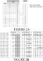
- the shift values m0 and m1 are illustrated in FIGURE 2A . It can be seen from FIGURE 2A that the second m-sequence (with m1 shift), is not dependent on the first m-sequence (with m0 shift) and thus first m-sequence can be combined with one of 112 second m-sequences.
- the second SSS part is made to depend on the first SSS part, or both the first SSS part and the PSS.
- the second SSS part and the first SSS part depend on the PSS in a manner that creates dependency between the second SSS part and the first SSS part.
- the second SSS part depends on both the PSS and the first SSS part in a manner that creates dependency between the second SSS part and the first SSS part via plural parameters that are used to determine the second SSS part and the first SSS part.
- the UE is enabled to, in many cases, ignore a second SSS part received from an incorrect cell as not complying with this dependency, or these dependencies.
- the dependencies may be expressed as mapping functions defining acceptable shift values for the first and/or second SSS part(s).
- the mapping functions take parameters used to generate the PSS and/or the first SSS part as input. These parameters may be the PCI components N ID 1 and/or N ID 2 , for example.
- the mapping functions may further depend on properly chosen constants a, b, c, d and/or e as discussed herein below.
- a different m-sequence is used with each separate N ID 2 value.
- the UE selects the used sequence based on the detected PSS and N ID 2 value.
- a long SSS sequence such as two times the length of subcarriers available in one symbol for the SSS, may be transmitted so that, for example, the first half of the sequence is transmitted as the first SSS part and the second half of the sequence is transmitted as the second SSS part. This is thus an alternative to the gold sequence obtained by the exclusive-or operation.
- Such a long SSS sequence would have a low PAPR due to the m-sequences themselves having low PAPR.
- the overall SSS sequence including the first and second SSS parts, may also be dependent on the location in the slot, or on the relative location in the burst, of the SSS transmissions.
- the first and/or second SSS part(s) transmitted there may be defined two time instances in the slot where the first and/or second SSS part(s) transmitted, a first and second time instance.
- the first SSS part may be the same sequence in both locations in the slot while the second SSS part may be different, dependent on whether the first SSS part location is the former or the latter location in the slot of two possible first SSS part locations in the slot. This also enables the UE to reject a second SSS part not complying with the dependency on the location in the slot of the first SSS part.
- the dependence between the SSS sequences can be created by modifying the 5G m-sequence shift selection as follows. Second SSS part shift m1 and first SSS part shift m0 are made dependent on each other based on a mapping function. This is done by adding second SSS part shift m1 dependence on PCI component N ID 2 , hence, creating dependence between second SSS part and first SSS part, as well as PSS.
- N ID 1 N ID 1 mod a + b ⁇ N ID 2 .
- the number of m0 shifts may be increased correspondingly.
- m 0 c ⁇ N ID 1 a ⁇ + d ⁇ N ID 2 .
- first SSS part and second SSS part are dependent only via the PCI component N ID 2 , which has only 3 values.
- the dependence of the first and second SSS parts on N ID 1 is formulated so that it does not create dependence between first SSS part and second SSS part.
- first SSS part and second SSS part are made dependent also via identifier N ID 1 in addition to the dependency on N ID 2 .
- N ID 1 identifier
- the cycle over which m0 and m1 return to same value may be increased.
- Shift values m0 and m1 are cyclic shift values.
- FIGURE 2B the detected first SSS part index, m0, is highlighted and candidate second SSS part indices, m1, that UE may assume to be from the same cell are likewise highlighted.
- the second SSS part index once the UE has detected PSS and the first SSS part, any second SSS part the UE detects with acceptable timing can be from the cell to which UE is synchronizing to, when the second SSS part has no dependence on the first SSS part. This is graphically indicated by the shading of all values of m1 in the "unrestricted" column of FIGURE 2B .
- only every third second SSS part can be from the same cell as the detected first SSS part. This is also indicated graphically by the shading of values in the m1 part of the "1 st embodiment" column in FIGURE 2B .
- only every ninth second SSS part (or PCI) index can be from the same cell as the detected first SSS part, further reducing the risk of the UE using an incorrect second SSS part which originates from another cell.
- a beneficial technical effect of the herein disclosed synchronization mechanisms is the provision of robust and reliable synchronization signal acquisition, reducing the risk of cell detection ambiguity by the UE when using an SSS partitioned into low-PAPR sequences, such as m-sequences, for example.
- FIGURE 3 illustrates an example apparatus capable of supporting at least some embodiments of the present invention.
- device 300 which may comprise, for example, a mobile communication device such as UE 110 or, in applicable parts, base station 130 of FIGURE 1 .
- processor 310 which may comprise, for example, a single- or multi-core processor wherein a single-core processor comprises one processing core and a multi-core processor comprises more than one processing core.
- Processor 310 may comprise, in general, a control device.
- Processor 310 may comprise more than one processor.
- device 300 may be a distributed device wherein processing of tasks takes place in more than one physical unit.
- Processor 310 may be a control device.
- a processing core may comprise, for example, a Cortex-A8 processing core manufactured by ARM Holdings or a Zen processing core designed by Advanced Micro Devices Corporation.
- a processing core or processor may be, or may comprise, at least one qubit.
- Processor 310 may comprise at least one Qualcomm Snapdragon and/or Intel Atom processor.
- Processor 310 may comprise at least one application-specific integrated circuit, ASIC.
- Processor 310 may comprise at least one field-programmable gate array, FPGA.
- Processor 310 optionally together with memory and computer instructions, may be means for performing method steps in device 300, such as detecting, accepting, using, receiving, transmitting and selecting, for example.
- Processor 310 may be configured, at least in part by computer instructions, to perform actions.
- a processor may comprise circuitry, or be constituted as circuitry or circuitries, the circuitry or circuitries being configured to perform phases of methods in accordance with embodiments described herein.
- circuitry may refer to one or more or all of the following: (a) hardware-only circuit implementations, such as implementations in only analogue and/or digital circuitry, and (b) combinations of hardware circuits and software, such as, as applicable: (i) a combination of analogue and/or digital hardware circuit(s) with software/firmware and (ii) any portions of hardware processor(s) with software (including digital signal processor(s)), software, and memory(ies) that work together to cause an apparatus, such as a mobile phone or base station, to perform various functions) and (c) hardware circuit(s) and or processor(s), such as a microprocessor(s) or a portion of a microprocessor(s), that requires software (e.g., firmware) for operation, but the software may not be present when it is not needed for operation.
- firmware firmware
- circuitry also covers an implementation of merely a hardware circuit or processor (or multiple processors) or portion of a hardware circuit or processor and its (or their) accompanying software and/or firmware.
- circuitry also covers, for example and if applicable to the particular claim element, a baseband integrated circuit or processor integrated circuit for a mobile device or a similar integrated circuit in server, a cellular network device, or other computing or network device.
- Device 300 may comprise memory 320.
- Memory 320 may comprise random-access memory and/or permanent memory.
- Memory 320 may comprise at least one RAM chip.
- Memory 320 may be a computer readable medium.
- Memory 320 may comprise solid-state, magnetic, optical and/or holographic memory, for example.
- Memory 320 may be at least in part accessible to processor 310.
- Memory 320 may be at least in part comprised in processor 310.
- Memory 320 may be means for storing information.
- Memory 320 may comprise computer instructions that processor 310 is configured to execute.
- processor 310 When computer instructions configured to cause processor 310 to perform certain actions are stored in memory 320, and device 300 overall is configured to run under the direction of processor 310 using computer instructions from memory 320, processor 310 and/or its at least one processing core may be considered to be configured to perform said certain actions.
- Memory 320 may be at least in part external to device 300 but accessible to device 300.
- Memory 320 may be transitory or non-transitory.
- non-transitory is a limitation of the medium itself (that is, tangible, not a signal) as opposed to a limitation on data storage persistency (for example, RAM vs. ROM).
- Device 300 may comprise a transmitter 330.
- Device 300 may comprise a receiver 340.
- Transmitter 330 and receiver 340 may be configured to transmit and receive, respectively, information in accordance with at least one cellular or non-cellular standard.
- Transmitter 330 may comprise more than one transmitter.
- Receiver 340 may comprise more than one receiver.
- Transmitter 330 and/or receiver 340 may be configured to operate in accordance with global system for mobile communication, GSM, wideband code division multiple access, WCDMA, 5G, long term evolution, LTE, IS-95, wireless local area network, WLAN, Ethernet and/or worldwide interoperability for microwave access, WiMAX, standards, for example.
- Device 300 may comprise a near-field communication, NFC, transceiver 350.
- NFC transceiver 350 may support at least one NFC technology, such as NFC, Bluetooth, Wibree or similar technologies.
- Device 300 may comprise user interface, UI, 360.
- UI 360 may comprise at least one of a display, a keyboard, a touchscreen, a vibrator arranged to signal to a user by causing device 300 to vibrate, a speaker or a microphone.
- a user may be able to operate device 300 via UI 360, for example to accept incoming telephone calls, to originate telephone calls or video calls, to browse the Internet, to manage digital files stored in memory 320 or on a cloud accessible via transmitter 330 and receiver 340, or via NFC transceiver 350, and/or to play games.
- Device 300 may comprise or be arranged to accept a user identity module 370.
- User identity module 370 may comprise, for example, a subscriber identity module, SIM, card installable in device 300.
- a user identity module 370 may comprise information identifying a subscription of a user of device 300.
- a user identity module 370 may comprise cryptographic information usable to verify the identity of a user of device 300 and/or to facilitate encryption of communicated information and billing of the user of device 300 for communication effected via device 300.
- Processor 310 may be furnished with a transmitter arranged to output information from processor 310, via electrical leads internal to device 300, to other devices comprised in device 300.
- a transmitter may comprise a serial bus transmitter arranged to, for example, output information via at least one electrical lead to memory 320 for storage therein.
- the transmitter may comprise a parallel bus transmitter.
- processor 310 may comprise a receiver arranged to receive information in processor 310, via electrical leads internal to device 300, from other devices comprised in device 300.
- Such a receiver may comprise a serial bus receiver arranged to, for example, receive information via at least one electrical lead from receiver 340 for processing in processor 310.
- the receiver may comprise a parallel bus receiver.
- Device 300 may comprise further devices not illustrated in FIGURE 3 .
- device 300 may comprise at least one digital camera.
- Some devices 300 may comprise a back-facing camera and a front-facing camera, wherein the back-facing camera may be intended for digital photography and the front-facing camera for video telephony.
- Device 300 may comprise a fingerprint sensor arranged to authenticate, at least in part, a user of device 300.
- device 300 lacks at least one device described above.
- some devices 300 may lack a NFC transceiver 350 and/or user identity module 370.
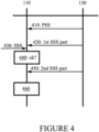
- FIGURE 4 illustrates signalling in accordance with at least some embodiments of the present invention.
- UE 110 of FIGURE 1 On the vertical axes are disposed, on the left, UE 110 of FIGURE 1 , and on the right, base station 130 likewise of FIGURE 1 . Time advances from the top toward the bottom.
- the signalling of FIGURE 4 relates to synchronization with a cell controlled by base station 130.
- base station 130 transmits the PSS, which the UE detects. Subsequently, in phase 420, base station 130 transmits, and the UE detects, the first SSS part as a low-PAPR sequence, such as, for example, an m-sequence.
- a low-PAPR sequence such as, for example, an m-sequence.
- phase 430 the UE detects a spurious second SSS part from another nearby cell.
- phase 440 the UE determines whether the index m1 of the second SSS part received in phase 430 satisfies a mapping function in accordance with the first or second embodiment described herein above. In this case, as the second SSS part of phase 430 is spurious and its index does not accidentally fall on one of the acceptable ones, UE 110 ignores the second SSS part of phase 430.
- base station 130 transmits, and the UE detects, the second SSS part as a low-PAPR sequence, such as, for example, an m-sequence.
- phase 440 may also comprise determining whether the second SSS part of phase 430 has been detected with timing the UE expects for a second SSS part from base station 130, and rejecting or ignoring the second SSS part of phase 430 responsive to determining that the timing does not match what the UE expects from a second SSS part from base station 130.
- the UE determines, in phase 460, that the index of the second SSS part received in phase 450 satisfies the mapping function(s) of the first or second embodiment, and consequently the UE accepts the second SSS part of phase 450.
- UE 110 proceeds with the synchronization process, for example by searching for physical broadcast channel, PBCH, symbols the base station may provide.
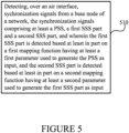
- FIGURE 5 is a flow graph of a method in accordance with at least some embodiments of the present invention.
- the phases of the illustrated method may be performed in UE 110, for example, or in a control device configured to control the functioning thereof, when installed therein.
- Phase 510 comprises detecting, over an air interface, synchronization signals from a base node of a network, the synchronization signals comprising at least a primary synchronization signal, PSS, a first secondary synchronization signal, SSS, part and a second SSS part, and wherein the first SSS part is detected based at least in part on a first mapping function having at least a first parameter used to generate the PSS as input, and the second SSS part is detected based at least in part on a second mapping function having at least a second parameter used to generate the first SSS part as input.
- FIGURE 6 is a flow graph of a method in accordance with at least some embodiments of the present invention.
- the phases of the illustrated method may be performed in a base station, for example, or in a control device configured to control the functioning thereof, when installed therein.
- Phase 610 comprises transmitting, over an air interface, synchronization signals, the synchronization signals comprising at least a primary synchronization signal, PSS, a secondary synchronization signal, SSS, first part and an SSS second part.
- Phase 620 comprises generating the first SSS part based at least in part on a first mapping function having at least a first parameter used to generate the PSS as input.
- Phase 630 comprises generating the second SSS part based at least in part on a second mapping function having at least a second parameter used to generate the first SSS part as input.
- At least some embodiments of the present invention find industrial application in wireless communication.
- UE 130, 135 base station 130A, 130B, 135A, 135B cells 140 core network node 150 network 300 - 350 structure of the device of FIGURE 3 410 - 450 phases of signalling of FIGURE 4 510 phase of the method of FIGURE 5
Landscapes
- Engineering & Computer Science (AREA)
- Computer Networks & Wireless Communication (AREA)
- Signal Processing (AREA)
- Databases & Information Systems (AREA)
- Mobile Radio Communication Systems (AREA)
Priority Applications (2)
| Application Number | Priority Date | Filing Date | Title |
|---|---|---|---|
| EP23218083.6A EP4576621A1 (fr) | 2023-12-19 | 2023-12-19 | Synchronisation |
| PCT/EP2024/083214 WO2025131536A1 (fr) | 2023-12-19 | 2024-11-22 | Synchronisation |
Applications Claiming Priority (1)
| Application Number | Priority Date | Filing Date | Title |
|---|---|---|---|
| EP23218083.6A EP4576621A1 (fr) | 2023-12-19 | 2023-12-19 | Synchronisation |
Publications (1)
| Publication Number | Publication Date |
|---|---|
| EP4576621A1 true EP4576621A1 (fr) | 2025-06-25 |
Family
ID=89224600
Family Applications (1)
| Application Number | Title | Priority Date | Filing Date |
|---|---|---|---|
| EP23218083.6A Pending EP4576621A1 (fr) | 2023-12-19 | 2023-12-19 | Synchronisation |
Country Status (2)
| Country | Link |
|---|---|
| EP (1) | EP4576621A1 (fr) |
| WO (1) | WO2025131536A1 (fr) |
Citations (4)
| Publication number | Priority date | Publication date | Assignee | Title |
|---|---|---|---|---|
| WO2016204883A1 (fr) * | 2015-06-18 | 2016-12-22 | Qualcomm Incorporated | Signaux de synchronisation secondaires pour un canal de synchronisation |
| EP3583711A1 (fr) * | 2017-03-04 | 2019-12-25 | LG Electronics Inc. -1- | Procédé de transmission de signal de synchronisation dans un système de communication sans fil et appareil associé |
| EP3639419A1 (fr) * | 2017-06-16 | 2020-04-22 | Motorola Mobility LLC | Procédé et appareil pour établir un ensemble d'une pluralité de séquences de signaux de synchronisation à utiliser avec une ou plusieurs cibles de communication |
| EP3905557A1 (fr) * | 2017-05-04 | 2021-11-03 | Huawei Technologies Co., Ltd. | Dispositif de traitement, noeud de réseau, dispositif client, et procédés associés |
-
2023
- 2023-12-19 EP EP23218083.6A patent/EP4576621A1/fr active Pending
-
2024
- 2024-11-22 WO PCT/EP2024/083214 patent/WO2025131536A1/fr active Pending
Patent Citations (4)
| Publication number | Priority date | Publication date | Assignee | Title |
|---|---|---|---|---|
| WO2016204883A1 (fr) * | 2015-06-18 | 2016-12-22 | Qualcomm Incorporated | Signaux de synchronisation secondaires pour un canal de synchronisation |
| EP3583711A1 (fr) * | 2017-03-04 | 2019-12-25 | LG Electronics Inc. -1- | Procédé de transmission de signal de synchronisation dans un système de communication sans fil et appareil associé |
| EP3905557A1 (fr) * | 2017-05-04 | 2021-11-03 | Huawei Technologies Co., Ltd. | Dispositif de traitement, noeud de réseau, dispositif client, et procédés associés |
| EP3639419A1 (fr) * | 2017-06-16 | 2020-04-22 | Motorola Mobility LLC | Procédé et appareil pour établir un ensemble d'une pluralité de séquences de signaux de synchronisation à utiliser avec une ou plusieurs cibles de communication |
Non-Patent Citations (1)
| Title |
|---|
| HUAWEI ET AL: "Evaluation of NR-SS", vol. RAN WG1, no. Qingdao, China; 20170627 - 20170630, 29 June 2017 (2017-06-29), XP051306050, Retrieved from the Internet <URL:http://www.3gpp.org/ftp/tsg_ran/WG1_RL1/TSGR1_AH/NR_AH_1706/Docs/> [retrieved on 20170629] * |
Also Published As
| Publication number | Publication date |
|---|---|
| WO2025131536A1 (fr) | 2025-06-26 |
Similar Documents
| Publication | Publication Date | Title |
|---|---|---|
| US10652882B2 (en) | Data transmission method, wireless network device, and communications system | |
| RU2717344C1 (ru) | Способы, устройства и узлы сети связи для осуществления процедуры доступа | |
| US10306573B2 (en) | System and method for transmitting a synchronization signal | |
| US11438872B2 (en) | Narrowband internet of things devices and method of operation thereof | |
| EP3863204B1 (fr) | Procédé d'émission de signal de synchronisation, appareil de réseau et appareil terminal | |
| RU2721757C1 (ru) | Способ и устройство для передачи информации | |
| EP3691374A1 (fr) | Procédé et dispositif de communication | |
| EP4221376A2 (fr) | Système de communication | |
| JP2019504565A (ja) | 復調基準信号を用いた位相ノイズトラッキング基準信号シーケンス生成のためのシステム及び方法 | |
| US10194411B2 (en) | User equipment and synchronization methods for device to device (D2D) communication | |
| CN113839765A (zh) | 无线通信系统中的参考信号生成方法和设备 | |
| CN114726473B (zh) | 同步信号发送和接收 | |
| EP4096123A1 (fr) | Recherche cellulaire améliorée et acquisition d'informations système | |
| CN107734630A (zh) | 信息传输方法、终端及网络设备 | |
| EP3533194B1 (fr) | Synchronisation dans des scénarios d'espacement de sous-porteuses ofdm mixtes | |
| EP4576621A1 (fr) | Synchronisation | |
| WO2020192923A1 (fr) | Adaptation de l'intervalle de garde dans des réseaux de communication sans fil | |
| EP3866374A1 (fr) | Améliorations pour accès initial dans des réseaux de communication cellulaires | |
| EP4601367A1 (fr) | Synchronisation | |
| US20250261145A1 (en) | Synchronization | |
| WO2025131390A1 (fr) | Synchronisation | |
| JP2026511936A (ja) | 物理ランダムアクセスチャネルの伝送方法と装置 | |
| WO2025073481A1 (fr) | Détermination d'un temps de traitement d'un équipement utilisateur | |
| CN120239054A (zh) | 通信方法及装置 | |
| HK40012872A (en) | Methods, devices and network nodes for performing an access procedure |
Legal Events
| Date | Code | Title | Description |
|---|---|---|---|
| PUAI | Public reference made under article 153(3) epc to a published international application that has entered the european phase |
Free format text: ORIGINAL CODE: 0009012 |
|
| STAA | Information on the status of an ep patent application or granted ep patent |
Free format text: STATUS: THE APPLICATION HAS BEEN PUBLISHED |
|
| AK | Designated contracting states |
Kind code of ref document: A1 Designated state(s): AL AT BE BG CH CY CZ DE DK EE ES FI FR GB GR HR HU IE IS IT LI LT LU LV MC ME MK MT NL NO PL PT RO RS SE SI SK SM TR |
|
| STAA | Information on the status of an ep patent application or granted ep patent |
Free format text: STATUS: REQUEST FOR EXAMINATION WAS MADE |
|
| 17P | Request for examination filed |
Effective date: 20251229 |