EP4576631A1 - Verfahren und vorrichtung zur drahtlosen kommunikation - Google Patents
Verfahren und vorrichtung zur drahtlosen kommunikation Download PDFInfo
- Publication number
- EP4576631A1 EP4576631A1 EP23849316.7A EP23849316A EP4576631A1 EP 4576631 A1 EP4576631 A1 EP 4576631A1 EP 23849316 A EP23849316 A EP 23849316A EP 4576631 A1 EP4576631 A1 EP 4576631A1
- Authority
- EP
- European Patent Office
- Prior art keywords
- target
- cell
- dci
- rrc signaling
- domain
- Prior art date
- Legal status (The legal status is an assumption and is not a legal conclusion. Google has not performed a legal analysis and makes no representation as to the accuracy of the status listed.)
- Pending
Links
Images

Classifications
-
- H—ELECTRICITY
- H04—ELECTRIC COMMUNICATION TECHNIQUE
- H04L—TRANSMISSION OF DIGITAL INFORMATION, e.g. TELEGRAPHIC COMMUNICATION
- H04L5/00—Arrangements affording multiple use of the transmission path
- H04L5/003—Arrangements for allocating sub-channels of the transmission path
- H04L5/0053—Allocation of signalling, i.e. of overhead other than pilot signals
- H04L5/0055—Physical resource allocation for ACK/NACK
-
- H—ELECTRICITY
- H04—ELECTRIC COMMUNICATION TECHNIQUE
- H04L—TRANSMISSION OF DIGITAL INFORMATION, e.g. TELEGRAPHIC COMMUNICATION
- H04L1/00—Arrangements for detecting or preventing errors in the information received
- H04L1/12—Arrangements for detecting or preventing errors in the information received by using return channel
- H04L1/16—Arrangements for detecting or preventing errors in the information received by using return channel in which the return channel carries supervisory signals, e.g. repetition request signals
- H04L1/18—Automatic repetition systems, e.g. Van Duuren systems
- H04L1/1812—Hybrid protocols; Hybrid automatic repeat request [HARQ]
-
- H—ELECTRICITY
- H04—ELECTRIC COMMUNICATION TECHNIQUE
- H04L—TRANSMISSION OF DIGITAL INFORMATION, e.g. TELEGRAPHIC COMMUNICATION
- H04L5/00—Arrangements affording multiple use of the transmission path
-
- H—ELECTRICITY
- H04—ELECTRIC COMMUNICATION TECHNIQUE
- H04L—TRANSMISSION OF DIGITAL INFORMATION, e.g. TELEGRAPHIC COMMUNICATION
- H04L5/00—Arrangements affording multiple use of the transmission path
- H04L5/0001—Arrangements for dividing the transmission path
- H04L5/0003—Two-dimensional division
- H04L5/0005—Time-frequency
- H04L5/0007—Time-frequency the frequencies being orthogonal, e.g. OFDM(A) or DMT
- H04L5/001—Time-frequency the frequencies being orthogonal, e.g. OFDM(A) or DMT the frequencies being arranged in component carriers
-
- H—ELECTRICITY
- H04—ELECTRIC COMMUNICATION TECHNIQUE
- H04L—TRANSMISSION OF DIGITAL INFORMATION, e.g. TELEGRAPHIC COMMUNICATION
- H04L5/00—Arrangements affording multiple use of the transmission path
- H04L5/003—Arrangements for allocating sub-channels of the transmission path
- H04L5/0053—Allocation of signalling, i.e. of overhead other than pilot signals
-
- H—ELECTRICITY
- H04—ELECTRIC COMMUNICATION TECHNIQUE
- H04W—WIRELESS COMMUNICATION NETWORKS
- H04W72/00—Local resource management
- H04W72/12—Wireless traffic scheduling
- H04W72/1263—Mapping of traffic onto schedule, e.g. scheduled allocation or multiplexing of flows
- H04W72/1273—Mapping of traffic onto schedule, e.g. scheduled allocation or multiplexing of flows of downlink data flows
-
- H—ELECTRICITY
- H04—ELECTRIC COMMUNICATION TECHNIQUE
- H04W—WIRELESS COMMUNICATION NETWORKS
- H04W72/00—Local resource management
- H04W72/20—Control channels or signalling for resource management
- H04W72/23—Control channels or signalling for resource management in the downlink direction of a wireless link, i.e. towards a terminal
- H04W72/232—Control channels or signalling for resource management in the downlink direction of a wireless link, i.e. towards a terminal the control data signalling from the physical layer, e.g. DCI signalling
Definitions
- the present disclosure relates to methods and apparatuses in wireless communication systems, specifically to transmission schemes and apparatuses for a plurality of carriers in such systems.
- Multi-carrier including carrier aggregation and dual-connection, etc.
- 3GPP has been evolving on multi-carrier technology from Rel-15.
- CA Carrier Aggregation
- NR 5G New Radio
- scheduling is only supported on the corresponding carrier wave or corresponding Physical Downlink Control Channel (PDCCH) for a plurality of scheduled carrier waves, and not supported through the same PDCCH on the same carrier.
- PDCH Physical Downlink Control Channel
- Rel-18 the topic of multi-carrier enhancement began to be discussed, and under this topic, one PDCCH can simultaneously scheduling data channels located on a plurality of carriers to improve overall performance.
- PDCCH scheduling in multi-carriers is only used as a typical application scenario or example; the present application is also applicable to other scenarios facing similar problems (such as other scenarios with higher requirements for controlling channel capacity, including but not limited to capacity enhancement systems, higher frequency systems, coverage enhancement systems, unauthorized frequency communication, Internet of Things (IoT), Ultra Reliable Low Latency Communication (URLLC) networks, and vehicular networks) can also obtain similar technical benefits.
- adoption of a unified solution across different scenarios can also help reduce hardware complexity and costs.
- the embodiments and features in the embodiments of the first node device of the present application may be applied to the second node device or vice versa.
- the interpretation of terminology, nouns, functions, variables (if not otherwise specified) in the present application may refer to the definitions in the 3GPP specification protocol TS36 series, TS38 series, and TS37 series. If desired, reference may be made to 3GPP criteria TS38.211, TS38.212, TS38.213, TS38.214, TS38.215, TS38.321, TS38.331, TS38.305, TS37.355 to assist in the understanding of the present application.
- a method in the first node for wireless communication comprising:
- the above described methods are characterized in that: The payload size of the DCI will be reduced when a plurality of serving cells are scheduled simultaneously by a single DCI, thereby improving system performance.
- the above described methods are characterized in that: Simplify the implementation of a plurality of serving cells being scheduled simultaneously by a single DCI, thereby reducing implementation complexity.
- the above described methods are characterized in that: While ensuring schedule flexibility, reduce signaling overhead and improve system efficiency.
- the target RRC signaling is PDSCH-Config.
- the target RRC signaling is ServingCellConfig.
- the above described methods are characterized in that:
- the method in the present application is also applicable to the transmission of uplink HARQ feedback.
- the above described methods are characterized in that:
- the method in the present application are equally applicable to the determination of uplink transmission power.
- the above described methods are characterized in that: The method in the present application are equally applicable to the determination of the cell occupied by PUCCH.
- the target domain set included in the target DCI comprises the second domain, which is used to determine that the cells included in the second cell set enter dormancy within active time; and when the number of cells included in the first cell set is greater than 1 or the configuration of the target RRC signaling indicates that the target DCI does not comprise the second domain, the target domain set included in the target DCI does not comprise the second domain, and the target DCI is not used for serving cell dormancy indication.
- the above described methods are characterized in that:
- the method in the present application are equally applicable to service cell sleep indications.
- a method in the second node for wireless communication comprising:
- the target RRC signaling is PDSCH-Config.
- the target RRC signaling is ServingCellConfig.
- the target domain set included in the target DCI comprises the second domain, which is used to determine that the cells included in the second cell set enter dormancy within active time; and when the number of cells included in the first cell set is greater than 1 or the configuration of the target RRC signaling indicates that the target DCI does not comprise the second domain, the target domain set included in the target DCI does not comprise the second domain, and the target DCI is not used for serving cell dormancy indication.
- a first node for wireless communication comprising:
- a second node for wireless communication comprising:
- the advantages of the scheme in the present application are: Simplifying the realization of a plurality of service cells being simultaneously scheduled by one DCI, thereby reducing the realization complexity; and reducing signaling overhead while ensuring schedule flexibility and improving system efficiency.
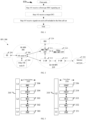
- Embodiment 1 exemplifies a processing flow diagram of a first node, as shown in FIG. 1 .
- each block represents a step.
- the first node in the present application receives a first-type RRC signaling set in Step 101; receives a target DCI in Step 102; and receives signal on each cell included in the first cell set in Step 103.
- the first-type RRC signaling set comprises a target RRC signaling, which is configured for a target cell; the target DCI is used for scheduling signals on the cells included in the first cell set, and the target cell is one of the cells in the first cell set; whether the target DCI comprises a target domain set depends on the number of cells in the first cell set; when the first cell set comprises one cell, whether the target DCI comprises a target domain set depends on the configuration of the target RRC signaling; and when the first cell set comprises a plurality of cells, whether the target DCI comprises a target domain set does not depend on the configurations of the target RRC signaling.
- the first-type RRC signaling set comprises an RRC signaling.
- the first-type RRC signaling set comprises a plurality of RRC signaling.
- the RRC signaling in the present application corresponds to an Information Element (IE) of TS 38.331.
- IE Information Element
- the target RRC signaling in the present application corresponds to an IE of TS 38.331.
- the physical layer channel occupied by the target DCI comprises PDCCH.
- the first cell set comprises only 1 cell.
- the first cell set comprises only 1 service cell.
- the first cell set comprises a plurality of cells.
- the first cell set comprises a plurality of service cells.
- the target DCI is used to determine the first cell set.
- the target DCI is used to indicate the first cell set.
- the target DCI is used to schedule Physical Downlink Shared Channel (PDSCH) on each cell included in the first cell set.
- PDSCH Physical Downlink Shared Channel
- the target cell is a service cell.
- the target cell is a cell.
- the target cell corresponds to one Component Carrier (CC).
- CC Component Carrier
- the target cell corresponds to a Physical Cell Identity (PCI).
- PCI Physical Cell Identity
- the target cell corresponds to a ServCellIndex.
- the target cell corresponds to a schedulingCellId.
- the target cell corresponds to a Carrier Indicator Field (CIF).
- CIF Carrier Indicator Field
- the number of cells included in the first cell set is 1, whether the target domain set is included in the target DCI depends on the configuration of the target RRC signaling.
- the number of cells included in the first cell set is greater than 1, whether the target DCI comprises the target domain set depends on the configuration of the target RRC signaling.
- the target DCI does not comprise the target domain set.
- the target DCI when the number of cells included in the first cell set is 1 and the configuration of the target RRC signaling indicates that the target DCI comprises the target domain set, the target DCI comprises the target domain set; and when the number of cells included in the first cell set is greater than 1, the target DCI does not comprise the target domain set.
- the configuration of the target RRC signaling is set to default.
- the configuration of the target RRC signaling is absent.
- the configuration of the target RRC signaling is present.
- the configuration of the target RRC signaling is applicable to the target cell only when the number of cells included in the first cell set is 1.
- the first-type RRC signaling set comprises a PDSCH-config IE.
- the first-type RRC signaling set comprises a PDSCH-ConfigCommon IE.
- the first-type RRC signaling set comprises a PUCCH-config IE.
- the first-type RRC signaling set comprises a PDSCH-ServingCellConfig IE.
- the first-type RRC signaling set comprises a ServingCellConfig IE.
- the target RRC signaling is a PDSCH-config IE.
- the target RRC signaling is a PDSCH-ConfigCommon IE.
- the target RRC signaling is a PUCCH-config IE.
- the target RRC signaling is a PDSCH-ServingCellConfig IE.
- the target RRC signaling is a ServingCellConfig IE.
- the domain in the target domain set is used to determine the antenna port used by the signal scheduled by the target DCI.
- the domain in the target domain set is used to determine the port of the Dedicated Demodulation Reference Signal (DMRS) included in the signal scheduled by the target DCI.
- DMRS Dedicated Demodulation Reference Signal
- the domain in the target domain set is used to determine the Code Division Multiplex, Code Multiplex (CDM) group of DMRS included in the signal scheduled by the target DCI.
- CDM Code Division Multiplex, Code Multiplex
- the domain in the target domain set is used to determine the number of CDM groups of DMRS included in the signal scheduled by the target DCI.
- the target RRC signaling is a PDSCH-config IE
- the configuration of the target RRC signaling corresponds to the antennaPortsFieldPresenceDCI-x-y domain in the PDSCH-config IE
- the target domain set in the target DCI comprises the Antenna port(s) domain, wherein x-y corresponds to the DCI format of the target DCI.
- the target DCI comprises the Antenna port(s) domain; when the number of cells included in the first cell set is greater than 1, the target DCI does not comprise the Antenna port(s) domain.
- the domain in the target domain set is used to determine the initialization parameters of the pseudorandom sequence generator adopted by the DMRS included by the signal scheduled by the target DCI.
- the target RRC signaling is a PDSCH-config IE
- the configuration of the target RRC signaling corresponds to the dmrs-SequenceInitializationDCI-x-y domain in the PDSCH-config IE
- the target domain set in the target DCI comprises the DMRS sequence initialization domain, wherein x-y corresponds to the DCI format of the target DCI.
- the target DCI comprises the DMRS sequence initialization domain; and when the number of cells included in the first cell set is greater than 1, the target DCI does not comprise the DMRS sequence initialization domain.
- the domain in the target domain set is used to determine the priority level corresponds to the signal scheduled by the target DCI.
- the target RRC signaling is a PDSCH-config IE
- the configuration of the target RRC signaling corresponds to the priorityIndicatorDCI-x-y domain in the PDSCH-config IE
- the target domain set in the target DCI comprises the Priority indicator domain, wherein x-y corresponds to the DCI format of the target DCI.
- the target DCI comprises the Priority indicator domain; and when the number of cells included in the first cell set is greater than 1, the target DCI does not comprise the Priority indicator domain.
- the domain in the target domain set is used to determine the PRB bundling mode of the signal scheduled by the target DCI.
- the domain in the target domain set is used to determine the PRB bundle size of the signal scheduled by the target DCI.
- the target RRC signaling is a PDSCH-config IE
- the configuration of the target RRC signaling corresponds to the prb-BundlingTypeDCI-x-y domain in the PDSCH-config IE
- the target domain set in the target DCI comprises the PRB bundling size indicator domain, where x-y corresponds to the DCI format of the target DCI.
- the target DCI comprises the PRB bundling size indicator domain; and when the number of cells included in the first cell set is greater than 1, the target DCI does not comprise the PRB bundling size indicator domain.
- the target DCI comprises the PRB bundling size indicator domain; and when the number of cells included in the first cell set is greater than 1, the target DCI does not comprise the PRB bundling size indicator domain.
- the physical layer channel occupied by the signal received over each cell included in the first cell set comprises PDSCH.
- the signal received on each cell included in the first cell set occupies a physical layer channel Synchronization Signal/physical broadcast channel Block (SSB).
- SSB Synchronization Signal/physical broadcast channel Block
- the physical layer channel PDCCH occupied by the signal received over each cell included in the first cell set is the physical layer channel PDCCH occupied by the signal received over each cell included in the first cell set.
- the transmission channel Downlink Shared Channel corresponds to the signal received on each cell included in the first cell set.
- the meaning of the target RRC signaling configured to the target cell comprises: The target RRC signaling is exclusive to the target cell.
- the meaning of the target RRC signaling configured to the target cell comprises:
- the target RRC signaling comprises the identification corresponds to the target cell, which is one of PCI, ServCellIndex, schedulingCellId, or CIF.
- Embodiment 2 exemplifies a schematic diagram of a network architecture, as shown in FIG. 2 .
- Embodiment 2 exemplifies a schematic diagram of a network architecture according to an embodiment of the present application, as shown in FIG. 2.
- Fig. 2 illustrates the V2X communication architecture under the 5G NewRadio (NR), Long-Term Evolution (LTE) and Long-Term Evolution Advanced (LTE-A) system architecture.
- the 5G NR or LTE network architecture may be referred to as some other suitable term of 5GSystem (5GS)/Evolved Packet System (EPS).
- 5GS 5GSystem
- EPS Evolved Packet System
- the V2X communication architecture of Embodiment 2 comprises User Equipment (UE) 201, UE241, Next-Generation Wireless Access Network (NG-RAN) 202, 5G Core Network (5GC)/Evolved Packet Core (EPC) 210, Home Subscriber Server (HSS)/Unified Data Management (UDM) 220, ProSe function 250, and ProSe application server 230.
- the V2X communication architecture may be interconnected with other access networks, but these entities/interfaces are not shown for simplicity. As shown, the V2X communication architecture provides packet exchange services. However, it will be readily understood by those skilled in the art that various concepts presented throughout the present application can be extended to a network or other cellular network providing circuit exchange services.
- NG-RAN comprises NR node B (gNB) 203 and other gNB204.
- the gNB203 provides for termination of the user and control plane protocol towards UE201.
- the gNB203 may be connected to other gNB204 via an Xn interface (e.g., backhaul).
- the gNB203 may also be referred to as a base station, a base transceiver station, a radio base station, a radio transceiver, a transceiver function, a Base Service Set (BSS), an Extension Service Set (ESS), a Transmit Receiving Node (TRP), or some other suitable term.
- gNB203 provides access points to 5GC/EPC210 for UE201.
- UE201 examples include cellular phone, smart phone, Session Initiation Protocol (SIP) phone, laptop computer, Personal Digital Assistant (PDA), satellite radio, non-ground base station communication, satellite mobile communication, global positioning system, multimedia device, video device, digital audio player (e.g., MP3 player), camera, game console, drone, aircraft, narrowband Internet of Things device, machine type communication device, land vehicle, automobile, wearable device, or any other similar functional apparatuses.
- Those skilled in the art may also refer to UE201 as mobile station, subscriber station, mobile unit, subscriber unit, wireless unit, remote unit, mobile apparatus, wireless apparatus, remote apparatus, mobile subscriber station, access terminal, mobile terminal, wireless terminal, remote terminal, handheld device, user agent, mobile client, or some other suitable term.
- gNB203 is connected to 5GC/EPC210 via the S1/NG interface.
- 5GC/EPC210 comprises Mobility Management Entity (MME)/Authentication Management Field (AMF)/Session Management Function (SMF) 211, other MME/AMF/SMF214, Service Gateway (S-GW)/UserPlaneFunction (UPF) 212 and Packet Date Network Gateway (P-GW)/UPF213.
- MME/AMF/SMF211 is a control node that processes signaling between UE201 and 5GC/EPC210.
- MME/AMF/SMF211 provides carrier and connection management. All user Internet Protocal (IP) packages are transmitted via S-GW/UPF212 which is itself connected to P-GW/UPF213.
- IP Internet Protocal
- the P-GW provides UE IP address assignment as well as other functions.
- the P-GW/UPF213 is connected to the Internet service 230.
- the Internet service 230 comprises an operator's corresponding Internet protocol service, which may include, inter alia, the Internet, an intranet, an IMS (IP Multimedia Subsystem, IP Multimedia Subsystem), and a packet exchange streaming service.
- the ProSe function 250 is a logical function for network-related behavior required for local service (Proximity-based Service (ProSe)), comprises a Direct Provisioning Function (DPF), a Direct Discovery Name Management Function, an EPC-level Discovery ProSe Function, etc.
- the ProSe application server 230 has the functions of storing the EPC ProSe user identification, mapping between the application layer user identification and the EPC ProSe user identification, and distributing the proSe restricted code suffix pool.
- the UE201 corresponds to the first node in the present application and the gNB203 corresponds to the second node in the present application.
- the UE201 supports a plurality of carrier waves being scheduled by the same DCI.
- the UE201 supports a plurality of service cells being scheduled with the same DCI.
- the UE201 supports trans-carrier scheduleing.
- the NR node B corresponds to the second node in the present application.
- the NR node B supports a plurality of carrier waves being scheduled by the same DCI.
- the NR node B supports that a plurality of service cells are scheduled by the same DCI.
- the NR node B supports trans-carrier scheduling.
- the NR node B is a base station.
- the NR node B is a cell.
- the NR node B comprises a plurality of cells.
- the NR node B is used to determine a transmission on a plurality of service cells.
- the first node in the present application corresponds to the UE201 and the second node in the present application corresponds to the NR node B.
- the first and second nodes in the present application are the UE201 and the gNB203 respectively.
- the first node in the present application is the UE201 and the second node in the present application is the UE241.
- Embodiment 3 illustrates a schematic diagram of an embodiment of a wireless protocol architecture for one user plane and a control plane of the present application, as shown in FIG. 3.
- FIG. 3 is a schematic diagram illustrating an embodiment of a radio protocol architecture for the user plane 350 and the control plane 300, where it demonstrates, with three layers, a radio protocol architecture for a control plane 300 between a first communication node device (RSU in UE, gNB or V2X) and a second communication node device (RSU in gNB, UE or V2X): Layers 1, 2 and 3.
- the layer 1 (L1 layer) is the lowest layer and implements various Physical Layer (PHY) signal processing functions.
- the L1 layer will be referred to herein as PHY301.
- the layer 2 (L2 layer) 305 is over PHY301 and is responsible for the link between the first communication node device and the second communication node device through PHY301.
- the L2 layer 305 comprises a Medium Access Control (MAC) sublayer 302, a Radio Link Control (RLC), sublayer 303, and a Packet Data Convergence Protocol (PDCP) sublayer 304 which terminate at the second communication node device.
- the PDCP sublayer 304 provides multiplexing between different radio carriers and logical channels.
- the PDCP sublayer 304 also provides security by encrypting the data packet and the PDCP sublayer 304 also provides inter-cell movement support for the second communication node device by the first communication node device.
- the RLC sublayer 303 provides segmentation and reassembly of the upper layer data packet, retransmission of the missing data packet, and reordering of the data packet to compensate for out-of-order reception due to HARQ.
- the MAC sublayer 302 provides multiplexing between logic and the transmission channel.
- the MAC sublayer 302 is also responsible for distributing various radio resources (e.g., resource blocks) in one cell between the first communication node devices.
- the MAC sublayer 302 is also responsible for HARQ operations.
- the Radio Resource Control (RRC) sublayer 306 in layer 3 (L3 layer) in the control plane 300 is responsible for obtaining the radio resources (i.e., radio carrier) and configuring the lower layer using RRC signaling between the second communication node device and the first communication node device.
- the radio protocol architecture of the user plane 350 comprises a layer 1 (L1 layer) and a layer 2 (L2 layer), the radio protocol architecture for the first communication node device and the second communication node device is generally the same as the corresponding layers and sublayers in the control plane 300 for the physical layer 351, the PDCP sublayer 354 in the L2 layer 355, the RLC sublayer 353 in the L2 layer 355, and the MAC sublayer 352 in the L2 layer 355.
- the PDCP sublayer 354 also provides header compression for upper-layer data packets to reduce radio transmission overhead.
- the L2 layer 355 in the user plane 350 also comprises a sublayer 356 of Service Data Adaption Protocol (SDAP), which is responsible for mapping between the QoS stream and Data Radio Bearer (DRB) to support the diversity of the business.
- SDAP Service Data Adaption Protocol
- DRB Data Radio Bearer
- the first communication node device may have several upper layers over the L2 layer 355 including a network layer (e.g., an IP layer) that terminates at the P-GW on the network side and an application layer that terminates at the other end of the connection (e.g., a far-end UE, a server, etc.).
- the wireless protocol architecture in FIG. 3 applies to the first node in the present application.
- the wireless protocol architecture in FIG. 3 applies to the second node in the present application.
- PDCP304 of the second communication node device is used to generate a schedule of the first communication node device.
- PDCP354 of the second communication node device is used to generate a schedule of the first communication node device.
- the first-type RRC signaling set is generated at the RRC306.
- the target DCI is generated at the PHY301 or the PHY351.
- the signal transmitted on each cell included in the first cell set is generated at the PHY301 or the PHY351.
- the signal transmitted over each cell included in the first cell set is generated at the MAC302 or MAC352.
- the signal transmitted over each cell included in the first cell set is generated at the RRC306.
- the first signal is generated at the PHY301 or the PHY351.
- the first signal is generated at the MAC302 or MAC352.
- the first signal is generated at the RRC306.
- the first node is a terminal.
- the first node is a relay.
- the second node is a terminal.
- the second node is a relay.
- the second node is a base station.
- the second node is one gNB.
- the second node is a Transmitter Receiver Point (TRP).
- TRP Transmitter Receiver Point
- the second node is used to manage a plurality of TRPs.
- the second node is a node for managing a plurality of cells.
- the second node is a node for managing a plurality of service cells.
- Embodiment 4 illustrates a schematic diagram of a first communication device and a second communication device according to the present application, as shown in FIG. 4.
- FIG. 4 is a block diagram of a first communication device 450 and a second communication device 410 in communication with each other over an access network.
- the first communication device 450 comprises a controller/processor 459, a memory 460, a data source 467, a transmission processor 468, a receiving processor 456, a multi-antenna transmission processor 457, a multi-antenna receiving processor 458, a transmitter/receiver 454, and an antenna 452.
- the second communication device 410 comprises a controller/processor 475, a memory 476, a receiving processor 470, a transmission processor 416, a multi-antenna receiving processor 472, a multi-antenna transmission processor 471, a transmitter/receiver 418, and an antenna 420.
- the upper data packet from the core network is provided to the controller/processor 475.
- the controller/processor 475 implements the functionality of the L2 layer.
- the controller/processor 475 provides header compression, encryption, packet segmentation and reordering, multiplexing between logic and the transport channel, and radio resource distribution to the first communication device 450 based on various priority measures.
- the controller/processor 475 is also responsible for the retransmission of the lost package and the signaling to the first communication device 450.
- the transmission processor 416 and the multi-antenna transmission processor 471 implement various signal processing functions for the L1 layer (i.e., the physical layer).
- the transmission processor 416 implements coding and interleaving to facilitate Forward Error Correction (FEC) at the second communication device 410 and mapping of signal clusters based on various modulation schemes (e.g., Binary Phase Shift Keying (BPSK), Quadrature Phase Shift Keying (QPSK), M-Phase Shift Keying (M-PSK), M-Quadrature Amplitude Modulation (M-QAM)).
- FEC Forward Error Correction
- the multi-antenna transmission processor 471 pre-codes encoded and modulated symbols in digital space, including codebook-based pre-coding and non-codebook-based pre-coding, and beam-based processing, generating one or more spatial streams.
- the transmission processor 416 maps each spatial stream to a sub-carrier, multiplexing with a reference signal (e.g., a frequency director) in the time and/or frequency domain, and then used an Inverse Fast Fourier Transform (IFFT) to generate a physical channel of the time domain multi-wave symbol stream on the carrier.
- IFFT Inverse Fast Fourier Transform
- the multi-antenna transmission processor 471 then sends the simulated pre-encoding/beaming operation for the time domain multi-carrier symbol flow.
- Each transmitter 418 converts the baseband multi-carrier symbol flow provided by the multi-antenna transmission processor 471 into a radio frequency flow, which is then provided to a different antenna 420.
- each receiver 454 receives a signal through its respective antenna 452. Each receiver 454 resumes information modulated onto the radio frequency carrier and provides a radio frequency flow to the receiving processor 456 into a base band multi carrier symbol flow.
- the receiving processor 456 and the multi-antenna receiving processor 458 implement various signal processing functions of the L1 layer.
- the multi-antenna receiving processor 458 performs a received analog pre-encoding/beam-engraving operation on the base band multi-carrier symbol flow from the receiver 454.
- the receiving processor 456 uses a Fast Fourier Transform (FFT) to convert the base band multi-carrier symbol flow from the time domain to the frequency domain after receiving the analog pre-encoding/beam-based manipulation.
- FFT Fast Fourier Transform
- the physical layer data signal and the reference signal are demultiplexed by the receiving processor 456, where the reference signal is used for channel estimation and the data signal recovers any spatial flow to the first communication device 450 for destination after multi-antenna detection by the multi-antenna receiving processor 458.
- the symbols on each spatial flow are demodulated and restored in the receiving processor 456 and generate a soft decision.
- the processor 456 is then decoded and de-interleaving the soft decision to restore the upper layer data and control signal transmitted by the second communication device 410 over the physical channel.
- the upper layer data and control signals are then provided to the controller/processor 459.
- the controller/processor 459 implements the functions of the L2 layer.
- the controller/processor 459 may be associated with a memory 460 storing program code and data.
- the memory 460 may be referred to as a computer-readable medium.
- the controller/processor 459 provides multiplexing between the transport and logical channel, packet reassembly, decryption, header decompression, control signal processing to recover the upper data packet from the core network.
- the upper data packet is then provided to all protocol layers above the L2 layer.
- Various control signals may also be provided to L3 for L3 processing.
- the data source 467 is used to provide the upper data packet to the controller/processor 459.
- the data source 467 represents all protocol layers above the L2 layer.
- the controller/processor 459 implements header compression, encryption, packet segmentation and reordering, and multiplexing between logic and transport channels based on wireless resource allocation, implementing L2 layer functions for the user plane and control plane.
- the controller/processor 459 is also responsible for the retransmission of the lost package and the signaling to the second communication device 410.
- the transmission processor 468 executes the modulation mapping, channel encoding, while the multi-antenna transmission processor 457 performs digital multi-antenna spatial pre-coding, including both codebook-based pre-coding and non-codebook-based pre-coding, and beam-based processing, and then the transmission processor 468 tailors the generated spatial stream to a multi-wave/single-wave symbol stream, which is provided to a different antenna 452 via the transmitter 454 after a simulated pre-encoded/beam operation in the multi-antenna transmission processor 457.
- Each transmitter 454 first converts the baseband symbol flow provided by the multi-antenna transmission processor 457 into a radio frequency symbol flow and then provides it to the antenna 452.
- the memory 476 may be referred to as a computer-readable medium.
- the controller/processor 475 In the transmission from the first communication device 450 to the second communication device 410, the controller/processor 475 provides multiplexing between the transport and logical channel, packet reassembly, decryption, header decompression, control signal processing to recover the upper data packet from the UE450.
- the upper data packet from the controller/processor 475 may be provided to the core network.
- the first communication device 450 apparatus comprises: at least one processor and at least one memory, and at least the one memory comprising computer program code; at least the one memory and the computer program code being configured to be used together with at least the one processor, the first communication device 450 apparatus at least: receiving a first-type RRC signaling set first, then receiving the target DCI and the received signals on each of cells included in a first cell set; the first-type RRC signaling set comprises a target RRC signaling, which is configured for a target cell; the target DCI is used for scheduling signals on the cells included in the first cell set, and the target cell is one of the cells in the first cell set; whether the target DCI comprises a target domain set depends on the number of cells in the first cell set; when the first cell set comprises one cell, whether the target DCI comprises a target domain set depends on the configuration of the target RRC signaling; and when the first cell set comprises a plurality of cells, whether the target DCI comprises a target domain set does not depend on the configurations of the target R
- the first communication device 450 comprises: A memory storing a computer-readable instruction program that when executed by at least one processor generates an action, the action comprises: receiving a first-type RRC signaling set first, then receiving the target DCI and the received signals on each of cells included in a first cell set; the first-type RRC signaling set comprises a target RRC signaling, which is configured for a target cell; the target DCI is used for scheduling signals on the cells included in the first cell set, and the target cell is one of the cells in the first cell set; whether the target DCI comprises a target domain set depends on the number of cells in the first cell set; when the first cell set comprises one cell, whether the target DCI comprises a target domain set depends on the configuration of the target RRC signaling; and when the first cell set comprises a plurality of cells, whether the target DCI comprises a target domain set does not depend on the configurations of the target RRC signaling.
- the second communication device 410 apparatus comprises: at least one processor and at least one memory, and at least the one memory comprising computer program code; at least the one memory and the computer program code being configured to be used together with at least the one processor.
- the second communication device 410 apparatus at least: sending a first-type RRC signaling set first, then sending the target DCI and the sent signals on each of cells included in a first cell set; the first-type RRC signaling set comprises a target RRC signaling, which is configured for a target cell; the target DCI is used for scheduling signals on the cells included in the first cell set, and the target cell is one of the cells in the first cell set; whether the target DCI comprises a target domain set depends on the number of cells in the first cell set; when the first cell set comprises one cell, whether the target DCI comprises a target domain set depends on the configuration of the target RRC signaling; and when the first cell set comprises a plurality of cells, whether the target DCI comprises a target domain set does not depend on the configurations of the target R
- the second communication device 410 apparatus comprises: A memory storing a computer-readable instruction program that when executed by at least one processor generates an action, the action comprises: sending a first-type RRC signaling set first, then sending the target DCI and the sent signals on each of cells included in a first cell set; the first-type RRC signaling set comprises a target RRC signaling, which is configured for a target cell; the target DCI is used for scheduling signals on the cells included in the first cell set, and the target cell is one of the cells in the first cell set; whether the target DCI comprises a target domain set depends on the number of cells in the first cell set; when the first cell set comprises one cell, whether the target DCI comprises a target domain set depends on the configuration of the target RRC signaling; and when the first cell set comprises a plurality of cells, whether the target DCI comprises a target domain set does not depend on the configurations of the target RRC signaling.
- the second communication device 410 corresponds to a second node in the present application.
- the first communication device 450 is a UE.
- the first communication device 450 is a terminal.
- the first communication device 450 is a relay.
- the first communication device 450 is a terminal having a plurality of carrier waves simultaneously scheduled through a first PDCCH.
- the second communication device 410 is a base station.
- the second communication device 410 is a relay.
- the second communication device 410 is a network device.
- the second communication device 410 is a service cell.
- the second communication device 410 is a base station having a plurality of carriers simultaneously scheduled through a first PDCCH.
- At least the first four of the antenna 452, the receiver 454, the multi-antenna receiving processor 458, the receiving processor 456, and the controller/processor 459 are used to receive a target DCI; and at least the first four of the antenna 420, the transmitter 418, the multi-antenna transmission processor 471, the transmission processor 416, the controller/processor 475 are used to send a target DCI.
- At least the first four of the antenna 452, the receiver 454, the multi-antenna receiving processor 458, the receiving processor 456, and the controller/processor 459 are used for receiving signals on each cell included in the first cell set; and at least the first four of the antenna 420, the transmitter 418, the multi-antenna transmission processor 471, the transmission processor 416, the controller/processor 475 are used for receiving signals on each cell included in the first cell set.
- At least the first four of the antenna 452, the transmitter 454, the multi-antenna transmission processor 457, the transmission processor 468, and the controller/processor 459 are used to send a first signal; and at least the first four of the antenna 420, the receiver 418, the multi-antenna receiving processor 472, the receiving processor 470, the controller/processor 475 are used to receive a first signal.
- the first-type RRC signaling set is received in step S10; the target DCI is received in step S11; and the signal is received on each cell included in the first cell set in step S12.
- the first-type RRC signaling set is sent in step S20; the target DCI is sent in step S21; and the signal is sent on each cell included in the first cell set in step S22.
- the first-type RRC signaling set comprises a target RRC signaling, which is configured for a target cell; the target DCI is used for scheduling signals on the cells included in the first cell set, and the target cell is one of the cells in the first cell set; whether the target DCI comprises a target domain set depends on the number of cells in the first cell set; when the first cell set comprises one cell, whether the target DCI comprises a target domain set depends on the configuration of the target RRC signaling; and when the first cell set comprises a plurality of cells, whether the target DCI comprises a target domain set does not depend on the configurations of the target RRC signaling.
- the target RRC signaling is PDSCH-Config.
- the target RRC signaling comprises PDSCH-Config.
- the target RRC signaling comprises PDSCH-Config IE.
- the name of the target RRC signaling including PDSCH.
- the name of the target RRC signaling including Config.
- the name of the target RRC signaling including PUCCH.
- the name of the target RRC signaling including ServingCell.
- the name of the target RRC signaling including Common.
- the target RRC signaling is ServingCellConfig.
- the target RRC signaling comprises ServingCellConfig.
- the target RRC signaling comprises ServingCellConfig IE.
- the target domain set included in the target DCI comprises the second domain, which is used to determine that the cells included in the second cell set enter dormancy within active time; and when the number of cells included in the first cell set is greater than 1 or the configuration of the target RRC signaling indicates that the target DCI does not comprise the second domain, the target domain set included in the target DCI does not comprise the second domain, and the target DCI is not used for serving cell dormancy indication.
- the target domain set does not comprise the second domain.
- the target domain set does not comprise the second domain.
- the target domain set does not comprise the target domain set.
- the target DCI comprises the second domain corresponds to the SCell dormancy indication domain in the DCI.
- the target RRC signaling is a ServingCellConfig IE
- the configuration of the target RRC signaling comprises at least one of the dormancyGroupWithinActiveTime domain or the DormancyGroupID domain in the ServingCellConfig IE
- the target domain set in the DCI comprises the SCell dormancy indication domain.
- the target DCI comprises the SCell dormancy indication domain; when the number of cells included in the first cell set is greater than 1.
- the SCell dormancy indication domain included in the target DCI is used to indicate that the cells included in the second cell set sleep within active time.
- the first cell set comprises M1 cells, which are positive integers.
- the M1 is equal to 1.
- the M1 is greater than 1.
- a signal is received over each cell included in the first cell set
- both x and y in x-y in the present application are non-negative integers.
- x-y in the present application represents DCI Format x-y.
- the second set of cells comprises M2 cells, which are positive integers.
- the M2 is equal to 1.
- the M2 is greater than 1.
- Embodiment 6 exemplifies a schematic diagram of a first signal of an embodiment, as shown in FIG. 6 .
- the first node U3 and the second node N4 communicate over a wireless link.
- the sequence in the present embodiment does not limit the sequence of signal transmission and the sequence of implementation in the present application.
- the embodiments, sub-embodiments, and ancillary embodiments of Embodiment 6 can be applied to Embodiment 5 of the present application; conversely, in the absence of conflicts, the embodiments, sub-embodiments, and ancillary embodiments of Embodiment 5 of the present application can be applied to Embodiment 6.
- a first signal is sent in step S30.
- a first signal is received in step S40.
- the first signal includes HARQ-ACK bits for the signal on each cell within the first cell set scheduled by the target DCI, and the first parameter is used for transmitting the first signal; when the number of cells in the first cell set is 1 and the configuration of the target RRC signaling indicates that the target DCI includes the target domain set, the target DCI includes the target domain set, and the first parameter is related to the target domain set included in the target DC; and when the number of cells in the first cell set is greater than 1 or the configuration of the target RRC signaling indicates that the target DCI does not comprise the target domain set, the first parameter is set to default.
- the first parameter is set to default.
- the first parameter is set to default.
- the first parameter when the number of cells included in the first cell set is greater than 1, the first parameter is set to default.
- the physical layer channel occupied by the first signal comprises PUCCH.
- the physical layer channel occupied by the first signal comprises Physical Uplink Shared Channel (PUSCH).
- PUSCH Physical Uplink Shared Channel
- the first signal comprises a Uplink Control Information (UCI).
- UCI Uplink Control Information
- the first signal is used to indicate whether the signal is properly received on each of the cells included in the first cell set scheduled by the target DCI.
- the target RRC signaling is PDSCH-config IE
- the configuration of the target RRC signaling corresponds to the pdsch-HARQ-ACK-OneShotFeedbackDCI-x-y domain in PDSCH-config IE
- the target domain set in the target DCI comprises the One-shot HARQ-ACK request domain, wherein x-y corresponds to the target DCIDCI format.
- the target DCI comprises the One-shot HARQ-ACK request domain; and when the number of cells included in the first cell set is greater than 1, the target DCI does not comprise the One-shot HARQ-ACK request domain.
- the One-shot HARQ-ACK request domain included in the target DCI is used to indicate whether the first signal comprises one-shot HARQ feedback.
- the meaning of the first parameter being used for sending of the first signal comprises: The first parameter is used to determine whether the first signal comprises one-shot HARQ feedback.
- the meaning of the first parameter being related to the target domain set included in the target DCI comprises:
- the first parameter corresponds to the One-shot HARQ-ACK request domain included in the target DCI, and the One-shot HARQ-ACK request domain is used to indicate whether the first signal comprises one-shot HARQ feedback.
- the meaning of "the first parameter is default” comprises: The first parameter is independent of the value indicated by the pdsch-HARQ-ACK-OneShotFeedbackDCI-x-y domain included in the target RRC signaling.
- the meaning of "the first parameter is default” comprises: The first parameter is used to determine that the first signal does not comprise one-shot HARQ feedback.
- the meaning of "the first parameter is default” comprises: The first node considers that the first signal does not comprise one-shot HARQ feedback.
- the meaning of "the first parameter is default” comprises: The value corresponds to the first parameter is independent of the RRC signaling.
- the target RRC signaling is PDSCH-config IE
- the configuration of the target RRC signaling corresponds to the pdsch-HARQ-ACK-EnhType3DCI-x-y domain in the PDSCH-config IE
- the target domain set in the target DCI comprises the Enhanced Type 3 codebook indicator domain, wherein x-y corresponds to the DCI format of the target DCI.
- the target DCI comprises the Enhanced Type 3 codebook indicator domain; and when the number of cells included in the first cell set is greater than 1, the target DCI does not comprise the Enhanced Type 3 codebook indicator domain.
- the Enhanced Type 3 codebook indicator domain included in the target DCI is used to indicate whether the first signal comprises Type 3 HARQ feedback.
- the Enhanced Type 3 codebook indicator domain included in the target DCI is used to indicate an Index of Type 3 HARQ feedback corresponds to the first signal.
- the Enhanced Type 3 codebook indicator domain included in the target DCI is used to indicate a PUCCH group corresponds to the first signal.
- the meaning of the first parameter being used for sending of the first signal comprises: The first parameter is used to determine whether the first signal is used for Type 3 HARQ feedback.
- the meaning of the first parameter being related to the target domain set included in the target DCI comprises:
- the first parameter corresponds to an Enhanced Type 3 codebook indicator domain included in the target DCI, and the Enhanced Type 3 codebook indicator domain is used to indicate whether the first signal is used for Type 3 HARQ feedback.
- the meaning of "the first parameter is default” comprises: The first parameter is independent of the value indicated by the pdsch-HARQ-ACK-EnhType3DCI-x-y domain in the target RRC signaling.
- the meaning of "the first parameter is default” comprises: The first parameter is used to determine that the first signal is not used for Type 3 HARQ feedback.
- the meaning of "the first parameter is default” comprises: The first node considers that the first signal is not used for Type 3 HARQ feedback.
- the target RRC signaling is PDSCH-config IE
- the configuration of the target RRC signaling corresponds to the pdsch-HARQ-ACK-RetxDCI-x-y domain in the PDSCH-config IE
- the target domain set in the target DCI comprises the HARQ-ACK retransmission indicator domain, wherein x-y corresponds to the DCI format of the target DCI.
- the DCI comprises the HARQ-ACK retransmission indicator domain; when the number of cells included in the first cell set is greater than 1, the target DCI does not comprise HARQ-ACK retransmission indicator domain.
- the HARQ-ACK retransmission indicator domain included in the target DCI is used to indicate whether to initiate a retransmission of the HARQ feedback for the data for the data scheduled by the target DCI.
- the HARQ-ACK retransmission indicator domain included in the target DCI is used to indicate whether the first signal is a retransmission of HARQ feedback for data scheduled by the target DCI.
- the meaning of the first parameter being used for sending of the first signal comprises: The first parameter is used to determine whether the first signal is used for HARQ retransmission, or the first parameter is used to determine if HARQ retransmission is triggered.
- the meaning of the first parameter being related to the target domain set included in the target DCI comprises:
- the first parameter corresponds to the HARQ-ACK retransmission indicator domain included in the target DCI, and the HARQ-ACK retransmission indicator domain is used to indicate whether the first signal is used for HARQ retransmission, or the HARQ-ACK retransmission indicator domain is used to indicate whether HARQ retransmission is triggered.
- the meaning of "the first parameter is default” comprises: the first parameter is independent of the value indicated by the pdsch-HARQ-ACK-RetxDCI-x-y domain in the target RRC signaling.
- the meaning of "the first parameter is default” comprises: The first parameter is used to determine that the first signal is not used for HARQ retransmission, or that the target DCI is not used to trigger HARQ retransmission.
- the meaning of "the first parameter is default” comprises: The first node considers that the first signal is not used for HARQ retransmission, or that the target DCI is not used to trigger HARQ retransmission.
- the second parameter is used to determine the TPC process adopted by the first signal; when the number of cells in the first cell set is 1 and the configuration of the target RRC signaling indicates that the target DCI includes the target domain set, the target DCI includes the target domain set, and the second parameter is related to the target domain set included in the target DCI; and when the number of cells in the first cell set is greater than 1 or the configuration of the target RRC signaling indicates that the target DCI does not comprise the target domain set, the second parameter is set to default.
- the second parameter is set to default.
- the second parameter is set to default.
- the second parameter is set to default.
- the target RRC signaling is PUCCH-config IE
- the configuration of the target RRC signaling corresponds to the secondTPCFieldDCI-x-y domain in the PUCCH-config IE
- the target domain set in the target DCI comprises Second TPC command for scheduled PUCCH domain, wherein x-y corresponds to the DCI format of the target DCI.
- the target DCI comprises the Second TPC command for scheduled PUCCH; and when the number of cells included in the first cell set is greater than 1, the target DCI does not comprise Second TPC command for scheduled PUCCH domain.
- the Second TPC command for scheduled PUCCH domain included in the target DCI is used to indicate the TPC command value corresponds to the first signal.
- the meaning of the TPC process employed by the second parameter for determining the first signal comprises: The second parameter is used to determine a TPC command value corresponds to the first signal.
- the meaning of the TPC process employed by the second parameter for determining the first signal comprises: The second parameter is used to determine a TPC process corresponds to the first signal.
- the meaning of the second parameter being related to the target domain set included in the target DCI comprises: The second parameter corresponds to the Second TPC command for scheduled PUCCH domain included in the target DCI, and the Second TPC command for scheduled PUCCH domain is used to indicate the TPC command value corresponds to the first signal.
- the meaning of "the second parameter is default” comprises: The second parameter is independent of the value indicated by the secondTPCFieldDCI-x-y domain in the target RRC signaling.
- the meaning of "the second parameter is default” comprises: The second parameter is used to determine that the first signal determines the TPC command value solely according to the TPC command for scheduled PUCCH in the target DCI.
- the meaning of "the second parameter is default” comprises: The first node considers that the first signal determines the TPC command value solely according to the TPC command for scheduled PUCCH in the target DCI.
- the third parameter is used to determine the cell in which the PUCCH occupied by the first signal is located; when the number of cells in the first cell set is 1 and the configuration of the target RRC signaling indicates that the target DCI comprises the target domain set, the target DCI comprises the target domain set, and the third parameter is related to the target domain set included in the target DCI; and when the number of cells in the first cell set is greater than 1 or the configuration of the target RRC signaling indicates that the target DCI does not comprise the target domain set, the third parameter is set to default.
- the third parameter is set to default.
- the third parameter is set to default.
- the third parameter is set to default.
- the target RRC signaling is a PDSCH-config IE
- the configuration of the target RRC signaling corresponds to the pucch-sSCellDynDCI-x-y domain in the PDSCH-config IE
- the target domain set in the target DCI comprises the PUCCH Cell indicator domain, wherein x-y corresponds to the DCI format of the target DCI.
- the meaning of "the third parameter is default” comprises: The third parameter is used to determine that the PUCCH occupied by the first signal is located at a location that cannot be dynamically switched.
- the meaning of "the third parameter is default” comprises: The cell in which the PUCCH occupied by the first signal is located is fixed.
- the meaning of "the third parameter is default” comprises: The cell in which the PUCCH occupied by the first signal is located is determined by a pucch-Cell in PDSCH-ServingCellConfigIE.
- the meaning of "the third parameter is default” comprises: The PUCCH occupied by the first signal is located in a cell that is Special Cell (SpCell) in a corresponding Cell group.
- SpCell Special Cell
- the meaning of "the third parameter is default” comprises: The value corresponds to the third parameter is independent of the RRC signaling.
- the meaning of "the third parameter is default” comprises: The PUCCH occupied by the first signal is located in a cell that is PUCCH SCell.
- the SCell is a Secondary Cell.
- the SCell is a Serving Cell.
- the step S30 is located after the step S12 in Embodiment 5.
- the step S40 is located after the step S22 in Embodiment 5.
- the step S30 is located after step S11 and before step S12 in embodiment 5.
- the step S40 is located after step S21 in embodiment 5 and before step S22.
- Embodiment 7 exemplifies a schematic diagram of target RRC signaling in an embodiment, as shown in FIG. 7 .
- the target RRC signaling is configured to the target cell, the target RRC signaling comprises a first configuration, and whether the target DCI comprises a first domain depends on the number of cells included in the first cell set in the present application.
- the target RRC signaling corresponds to PUCCH-config IE
- the first configuration corresponds to the secondTPCFieldDCI-x-y-r-z, wherein x-y represents the corresponding DCI format, r-z represents the release version, and the first domain corresponds to the Second TPC command for scheduled PUCCH domain in the DCI.
- the target RRC signaling corresponds to PDSCH-config IE
- the first configuration corresponds to antennaPortsFieldPresenceDCI-x-y-r-z, wherein x-y represents the corresponding DCI format, r-z represents the release version, and the first domain corresponds to the Antenna port domain in the DCI.
- the target RRC signaling corresponds to PDSCH-config IE
- the first configuration corresponds to dmrs-SequenceInitializationDCI-x-y-r-z, wherein x-y represents corresponding DCI format, r-z represents the release version, and the first domain corresponds to the DMRS sequence initialization domain in the DCI.
- the target RRC signaling corresponds to PDSCH-config IE
- the first configuration corresponds to the priorityIndicatorDCI-x-y-r-z, wherein x-y represents the corresponding DCI format, r-z represents the release version, and the first domain corresponds to the Priority indicator domain in the DCI.
- the target RRC signaling corresponds to PDSCH-config IE
- the first configuration corresponds to pdsch-HARQ-ACK-EnhType3DCI-x-y-r-z, wherein x-y represents the corresponding DCI format, r-z represents the release version, and the first domain corresponds to the Enhanced Type 3 codebook indicator domain in the DCI.
- the target RRC signaling corresponds to PDSCH-config IE
- the first configuration corresponds to pdsch-HARQ-ACK-RetxDCI-x-y-r-z, wherein x-y represents corresponding DCI format, r-z represents release version, and the first domain corresponds to the HARQ-ACK retransmission indicator domain in the DCI.
- the target RRC signaling corresponds to PDSCH-config IE
- the first configuration corresponds to pucch-sSCellDynDCI-x-y-r-z, wherein x-y represents the corresponding DCI format, r-z represents the release version, and the first domain corresponds to the PUCCH Cell indicator domain in the DCI.
- the target RRC signaling corresponds to PDSCH-config IE
- the first configuration corresponds to prb-BundlingType
- the first domain corresponds to a PRB bundling size indicator domain in DCI.
- the target RRC signaling corresponds to ServingCellConfig IE
- the first configuration corresponds to dormancyGroupWithinActiveTime
- the first domain corresponds to a SCell dormancy indication domain in DCI.
- the target RRC signaling corresponds to ServingCellConfig IE
- the first configuration corresponds to DormancyGroupID-r-z, wherein r-z represents the release version
- the first domain corresponds to the SCell dormancy indication domain in the DCI.
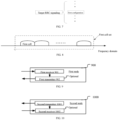
- Embodiment 8 exemplifies a schematic diagram of a first cell set according to an embodiment of the present application, as shown in FIG. 8 .
- the first cell set comprises M1 cells, the first cell being one of the M1 cells.
- the first cell is any one of the M1 cells.
- the M1 is a positive integer greater than 1.
- the target DCI is used to indicate the M1 cells.
- RRC signaling is used to indicate the M1 cells.
- Embodiment 9 exemplifies a block structural diagram of a processing apparatus in a first node; as shown in FIG. 9 .
- the first node 900 comprises a first receiver 901.
- a first receiver 901 receiving a first-type RRC signaling set, receiving a target DCI, and receiving a signal on each cell included in the first cell set;
- the first-type RRC signaling set comprises a target RRC signaling, which is configured for a target cell; the target DCI is used for scheduling signals on the cells included in the first cell set, and the target cell is one of the cells in the first cell set; whether the target DCI comprises a target domain set depends on the number of cells in the first cell set; when the first cell set comprises one cell, whether the target DCI comprises a target domain set depends on the configuration of the target RRC signaling; and when the first cell set comprises a plurality of cells, whether the target DCI comprises a target domain set does not depend on the configurations of the target RRC signaling.
- the target RRC signaling is PDSCH-Config.
- the target RRC signaling is PDSCH-Config.
- the target RRC signaling is ServingCellConfig.
- the first node comprises:
- the first node comprises:
- the first node comprises:
- the target domain set included in the target DCI comprises the second domain, which is used to determine that the cells included in the second cell set enter dormancy within active time; and when the number of cells included in the first cell set is greater than 1 or the configuration of the target RRC signaling indicates that the target DCI does not comprise the second domain, the target domain set included in the target DCI does not comprise the second domain, and the target DCI is not used for serving cell dormancy indication.
- the first transmitter 902 is optional.
- the first receiver 901 comprises at least the first four of an antenna 452, a receiver 454, a multi-antenna receiving processor 458, a receiving processor 456, and a controller/processor 459 of Embodiment 4.
- the first transmitter 902 comprises at least the first four of an antenna 452, a transmitter 454, a multi-antenna transmission processor 457, a transmission processor 468, a controller/processor 459 of Embodiment 4.
- Embodiment 10 exemplifies a block structural diagram of a processing apparatus in a second node. , as shown in FIG. 10 .
- the second node 1000 comprises a second transmitter 1001. a second transmitter 1001, sending a first-type RRC signaling set, sending a target DCI, and sending a signal on each cell included in the first cell set;
- the first-type RRC signaling set comprises a target RRC signaling, which is configured for a target cell; the target DCI is used for scheduling signals on the cells included in the first cell set, and the target cell is one of the cells in the first cell set; whether the target DCI comprises a target domain set depends on the number of cells in the first cell set; when the first cell set comprises one cell, whether the target DCI comprises a target domain set depends on the configuration of the target RRC signaling; and when the first cell set comprises a plurality of cells, whether the target DCI comprises a target domain set does not depend on the configurations of the target RRC signaling.
- the target RRC signaling is PDSCH-Config.
- the target RRC signaling is ServingCellConfig.
- the first node comprises:
- the first node comprises:
- the first node comprises:
- the target domain set included in the target DCI comprises the second domain, which is used to determine that the cells included in the second cell set enter dormancy within active time; and when the number of cells included in the first cell set is greater than 1 or the configuration of the target RRC signaling indicates that the target DCI does not comprise the second domain, the target domain set included in the target DCI does not comprise the second domain, and the target DCI is not used for serving cell dormancy indication.
- the second receiver 1002 is optional.
- the first transmitter 1001 comprises at least the first four of an antenna 420, a transmitter 418, a multi-antenna transmission processor 471, a transmission processor 416, a controller/processor 475 of Embodiment 4.
- the second receiver 1002 comprises at least the first four of an antenna 420, a receiver 418, a multi-antenna receiving processor 472, a receiving processor 470, a controller/processor 475 of embodiment 4.
- the first node in the present application includes, but is not limited to, cell phones, tablets, notebooks, network cards, low-power devices, eMTC devices, NB-IoT devices, in-vehicle communication devices, transportation vehicles, cars, RSUs, aircrafts, airplanes, drones, remotely controlled aircrafts and other wireless communication devices.
- the second node in the present application includes, but is not limited to, macro cellular base stations, micro cell base stations, small cellular base stations, femtocell base stations, relay base stations, eNB, gNB, Transmission Reception Points (TRP), GNSS, relay satellites, satellite base stations, aerial base stations, RSUs, drones, testing equipment, such as transceivers or signaling testers simulating part of the functions of a base station, and other wireless communication devices.
- TRP Transmission Reception Points
Landscapes
- Engineering & Computer Science (AREA)
- Signal Processing (AREA)
- Computer Networks & Wireless Communication (AREA)
- Mobile Radio Communication Systems (AREA)
Applications Claiming Priority (2)
| Application Number | Priority Date | Filing Date | Title |
|---|---|---|---|
| CN202210915272.9A CN117560120A (zh) | 2022-08-01 | 2022-08-01 | 一种用于无线通信的方法和装置 |
| PCT/CN2023/110079 WO2024027608A1 (zh) | 2022-08-01 | 2023-07-31 | 一种用于无线通信的方法和装置 |
Publications (1)
| Publication Number | Publication Date |
|---|---|
| EP4576631A1 true EP4576631A1 (de) | 2025-06-25 |
Family
ID=89811569
Family Applications (1)
| Application Number | Title | Priority Date | Filing Date |
|---|---|---|---|
| EP23849316.7A Pending EP4576631A1 (de) | 2022-08-01 | 2023-07-31 | Verfahren und vorrichtung zur drahtlosen kommunikation |
Country Status (4)
| Country | Link |
|---|---|
| US (1) | US20260089741A1 (de) |
| EP (1) | EP4576631A1 (de) |
| CN (1) | CN117560120A (de) |
| WO (1) | WO2024027608A1 (de) |
Families Citing this family (1)
| Publication number | Priority date | Publication date | Assignee | Title |
|---|---|---|---|---|
| CN120224453A (zh) * | 2024-10-16 | 2025-06-27 | 荣耀终端股份有限公司 | 一种被用于无线通信的多小区调度的节点中的方法和装置 |
Family Cites Families (5)
| Publication number | Priority date | Publication date | Assignee | Title |
|---|---|---|---|---|
| CN114026939B (zh) * | 2019-06-21 | 2025-07-25 | 夏普株式会社 | 用于下行链路控制信息(dci)格式的dci的用户设备、基站和方法 |
| CN113271608B (zh) * | 2020-02-14 | 2025-02-25 | 华为技术有限公司 | 配置信息获取方法及装置 |
| CN113382449A (zh) * | 2020-02-25 | 2021-09-10 | 索尼公司 | 用于无线通信的电子设备和方法、计算机可读存储介质 |
| JP7479889B2 (ja) * | 2020-03-26 | 2024-05-09 | シャープ株式会社 | 端末装置、基地局装置、および、通信方法 |
| CN119012263A (zh) * | 2020-06-02 | 2024-11-22 | 上海朗帛通信技术有限公司 | 一种被用于无线通信的节点中的方法和装置 |
-
2022
- 2022-08-01 CN CN202210915272.9A patent/CN117560120A/zh active Pending
-
2023
- 2023-07-31 US US19/159,920 patent/US20260089741A1/en active Pending
- 2023-07-31 WO PCT/CN2023/110079 patent/WO2024027608A1/zh not_active Ceased
- 2023-07-31 EP EP23849316.7A patent/EP4576631A1/de active Pending
Also Published As
| Publication number | Publication date |
|---|---|
| WO2024027608A1 (zh) | 2024-02-08 |
| US20260089741A1 (en) | 2026-03-26 |
| CN117560120A (zh) | 2024-02-13 |
Similar Documents
| Publication | Publication Date | Title |
|---|---|---|
| CN113225156B (zh) | 一种被用于无线通信的节点中的方法和装置 | |
| EP4576631A1 (de) | Verfahren und vorrichtung zur drahtlosen kommunikation | |
| WO2026007543A1 (zh) | 用于无线通信的节点中的与信令中的域有关的方法和装置 | |
| WO2025251887A1 (zh) | 用于无线通信的节点中的与pucch有关的方法和装置 | |
| EP4583604A1 (de) | Verfahren und vorrichtung zur drahtlosen kommunikation | |
| EP4580100A1 (de) | Verfahren und vorrichtung zur verwendung in drahtloskommunikationsknoten | |
| WO2024022239A1 (zh) | 一种用于无线通信的方法和装置 | |
| CN115715014A (zh) | 一种被用于无线通信的节点中的方法和装置 | |
| CN115119323A (zh) | 一种被用于无线通信的节点中的方法和装置 | |
| EP4601348A1 (de) | Verfahren und vorrichtung zur drahtlosen kommunikation | |
| EP4618637A1 (de) | Verfahren für knoten der drahtlosen kommunikation und vorrichtung | |
| EP4637220A1 (de) | Verfahren und vorrichtung zur verwendung in einem knoten für drahtlose kommunikation | |
| EP4668947A1 (de) | Verfahren und vorrichtung zur verwendung in einem knoten für drahtlose kommunikation | |
| CN113206727B (zh) | 一种被用于无线通信的节点中的方法和装置 | |
| EP4668980A1 (de) | Verfahren und vorrichtung zur verwendung in einem knoten für drahtlose kommunikation | |
| EP4625865A1 (de) | Verfahren und vorrichtung zur verwendung in einem knoten für drahtlose kommunikation | |
| EP4664811A1 (de) | Verfahren und vorrichtung zur verwendung in einem knoten für drahtlose kommunikation | |
| EP4611453A1 (de) | Verfahren und vorrichtung für knoten zur verwendung in der drahtlosen kommunikation | |
| EP4676143A1 (de) | Verfahren und vorrichtung zur verwendung in einem knoten für drahtlose kommunikation | |
| EP4593315A1 (de) | Verfahren und vorrichtung zur verwendung in einem knoten für drahtlose kommunikation | |
| CN114374484B (zh) | 一种被用于无线通信的节点中的方法和装置 | |
| CN113497686B (zh) | 一种被用于无线通信的节点中的方法和装置 | |
| WO2026011924A1 (zh) | 用于无线通信的节点中的与速率匹配有关的方法和装置 | |
| WO2025213969A1 (zh) | 一种被用于无线通信的节点中的与pucch重复有关的方法和装置 | |
| WO2024032425A1 (zh) | 一种用于无线通信的方法和装置 |
Legal Events
| Date | Code | Title | Description |
|---|---|---|---|
| STAA | Information on the status of an ep patent application or granted ep patent |
Free format text: STATUS: THE INTERNATIONAL PUBLICATION HAS BEEN MADE |
|
| PUAI | Public reference made under article 153(3) epc to a published international application that has entered the european phase |
Free format text: ORIGINAL CODE: 0009012 |
|
| STAA | Information on the status of an ep patent application or granted ep patent |
Free format text: STATUS: REQUEST FOR EXAMINATION WAS MADE |
|
| 17P | Request for examination filed |
Effective date: 20250515 |
|
| AK | Designated contracting states |
Kind code of ref document: A1 Designated state(s): AL AT BE BG CH CY CZ DE DK EE ES FI FR GB GR HR HU IE IS IT LI LT LU LV MC ME MK MT NL NO PL PT RO RS SE SI SK SM TR |
|
| RAP1 | Party data changed (applicant data changed or rights of an application transferred) |
Owner name: APOGEE NETWORKS, LLC |
|
| DAV | Request for validation of the european patent (deleted) | ||
| DAX | Request for extension of the european patent (deleted) |