EP4576636A2 - Structure de canal physique de commande de liaison montante (spucch) court - Google Patents
Structure de canal physique de commande de liaison montante (spucch) court Download PDFInfo
- Publication number
- EP4576636A2 EP4576636A2 EP25174975.0A EP25174975A EP4576636A2 EP 4576636 A2 EP4576636 A2 EP 4576636A2 EP 25174975 A EP25174975 A EP 25174975A EP 4576636 A2 EP4576636 A2 EP 4576636A2
- Authority
- EP
- European Patent Office
- Prior art keywords
- sequence
- interlace
- wtru
- channel
- golay
- Prior art date
- Legal status (The legal status is an assumption and is not a legal conclusion. Google has not performed a legal analysis and makes no representation as to the accuracy of the status listed.)
- Pending
Links
Images








Classifications
-
- H—ELECTRICITY
- H04—ELECTRIC COMMUNICATION TECHNIQUE
- H04L—TRANSMISSION OF DIGITAL INFORMATION, e.g. TELEGRAPHIC COMMUNICATION
- H04L1/00—Arrangements for detecting or preventing errors in the information received
- H04L1/0001—Systems modifying transmission characteristics according to link quality, e.g. power backoff
- H04L1/0006—Systems modifying transmission characteristics according to link quality, e.g. power backoff by adapting the transmission format
-
- H—ELECTRICITY
- H04—ELECTRIC COMMUNICATION TECHNIQUE
- H04L—TRANSMISSION OF DIGITAL INFORMATION, e.g. TELEGRAPHIC COMMUNICATION
- H04L1/00—Arrangements for detecting or preventing errors in the information received
- H04L1/12—Arrangements for detecting or preventing errors in the information received by using return channel
- H04L1/16—Arrangements for detecting or preventing errors in the information received by using return channel in which the return channel carries supervisory signals, e.g. repetition request signals
- H04L1/1607—Details of the supervisory signal
-
- H—ELECTRICITY
- H04—ELECTRIC COMMUNICATION TECHNIQUE
- H04L—TRANSMISSION OF DIGITAL INFORMATION, e.g. TELEGRAPHIC COMMUNICATION
- H04L1/00—Arrangements for detecting or preventing errors in the information received
- H04L1/12—Arrangements for detecting or preventing errors in the information received by using return channel
- H04L1/16—Arrangements for detecting or preventing errors in the information received by using return channel in which the return channel carries supervisory signals, e.g. repetition request signals
- H04L1/18—Automatic repetition systems, e.g. Van Duuren systems
- H04L1/1829—Arrangements specially adapted for the receiver end
- H04L1/1861—Physical mapping arrangements
-
- H—ELECTRICITY
- H04—ELECTRIC COMMUNICATION TECHNIQUE
- H04L—TRANSMISSION OF DIGITAL INFORMATION, e.g. TELEGRAPHIC COMMUNICATION
- H04L27/00—Modulated-carrier systems
- H04L27/26—Systems using multi-frequency codes
- H04L27/2601—Multicarrier modulation systems
- H04L27/2602—Signal structure
- H04L27/2605—Symbol extensions, e.g. Zero Tail, Unique Word [UW]
- H04L27/2607—Cyclic extensions
-
- H—ELECTRICITY
- H04—ELECTRIC COMMUNICATION TECHNIQUE
- H04L—TRANSMISSION OF DIGITAL INFORMATION, e.g. TELEGRAPHIC COMMUNICATION
- H04L27/00—Modulated-carrier systems
- H04L27/26—Systems using multi-frequency codes
- H04L27/2601—Multicarrier modulation systems
- H04L27/2614—Peak power aspects
- H04L27/2615—Reduction thereof using coding
-
- H—ELECTRICITY
- H04—ELECTRIC COMMUNICATION TECHNIQUE
- H04L—TRANSMISSION OF DIGITAL INFORMATION, e.g. TELEGRAPHIC COMMUNICATION
- H04L27/00—Modulated-carrier systems
- H04L27/26—Systems using multi-frequency codes
- H04L27/2601—Multicarrier modulation systems
- H04L27/2626—Arrangements specific to the transmitter only
- H04L27/2627—Modulators
- H04L27/2634—Inverse fast Fourier transform [IFFT] or inverse discrete Fourier transform [IDFT] modulators in combination with other circuits for modulation
-
- H—ELECTRICITY
- H04—ELECTRIC COMMUNICATION TECHNIQUE
- H04L—TRANSMISSION OF DIGITAL INFORMATION, e.g. TELEGRAPHIC COMMUNICATION
- H04L5/00—Arrangements affording multiple use of the transmission path
- H04L5/0001—Arrangements for dividing the transmission path
- H04L5/0014—Three-dimensional division
- H04L5/0016—Time-frequency-code
-
- H—ELECTRICITY
- H04—ELECTRIC COMMUNICATION TECHNIQUE
- H04L—TRANSMISSION OF DIGITAL INFORMATION, e.g. TELEGRAPHIC COMMUNICATION
- H04L5/00—Arrangements affording multiple use of the transmission path
- H04L5/003—Arrangements for allocating sub-channels of the transmission path
- H04L5/0037—Inter-user or inter-terminal allocation
- H04L5/0041—Frequency-non-contiguous
-
- H—ELECTRICITY
- H04—ELECTRIC COMMUNICATION TECHNIQUE
- H04L—TRANSMISSION OF DIGITAL INFORMATION, e.g. TELEGRAPHIC COMMUNICATION
- H04L5/00—Arrangements affording multiple use of the transmission path
- H04L5/003—Arrangements for allocating sub-channels of the transmission path
- H04L5/0053—Allocation of signalling, i.e. of overhead other than pilot signals
-
- H—ELECTRICITY
- H04—ELECTRIC COMMUNICATION TECHNIQUE
- H04L—TRANSMISSION OF DIGITAL INFORMATION, e.g. TELEGRAPHIC COMMUNICATION
- H04L5/00—Arrangements affording multiple use of the transmission path
- H04L5/003—Arrangements for allocating sub-channels of the transmission path
- H04L5/0053—Allocation of signalling, i.e. of overhead other than pilot signals
- H04L5/0055—Physical resource allocation for ACK/NACK
-
- H—ELECTRICITY
- H04—ELECTRIC COMMUNICATION TECHNIQUE
- H04W—WIRELESS COMMUNICATION NETWORKS
- H04W16/00—Network planning, e.g. coverage or traffic planning tools; Network deployment, e.g. resource partitioning or cells structures
- H04W16/14—Spectrum sharing arrangements between different networks
-
- H—ELECTRICITY
- H04—ELECTRIC COMMUNICATION TECHNIQUE
- H04W—WIRELESS COMMUNICATION NETWORKS
- H04W72/00—Local resource management
- H04W72/04—Wireless resource allocation
- H04W72/044—Wireless resource allocation based on the type of the allocated resource
- H04W72/0453—Resources in frequency domain, e.g. a carrier in FDMA
-
- H—ELECTRICITY
- H04—ELECTRIC COMMUNICATION TECHNIQUE
- H04W—WIRELESS COMMUNICATION NETWORKS
- H04W72/00—Local resource management
- H04W72/20—Control channels or signalling for resource management
- H04W72/21—Control channels or signalling for resource management in the uplink direction of a wireless link, i.e. towards the network
-
- H—ELECTRICITY
- H04—ELECTRIC COMMUNICATION TECHNIQUE
- H04J—MULTIPLEX COMMUNICATION
- H04J13/00—Code division multiplex systems
- H04J13/0007—Code type
- H04J13/0011—Complementary
- H04J13/0014—Golay
-
- H—ELECTRICITY
- H04—ELECTRIC COMMUNICATION TECHNIQUE
- H04L—TRANSMISSION OF DIGITAL INFORMATION, e.g. TELEGRAPHIC COMMUNICATION
- H04L27/00—Modulated-carrier systems
- H04L27/18—Phase-modulated carrier systems, i.e. using phase-shift keying
- H04L27/20—Modulator circuits; Transmitter circuits
- H04L27/2032—Modulator circuits; Transmitter circuits for discrete phase modulation, e.g. in which the phase of the carrier is modulated in a nominally instantaneous manner
- H04L27/2053—Modulator circuits; Transmitter circuits for discrete phase modulation, e.g. in which the phase of the carrier is modulated in a nominally instantaneous manner using more than one carrier, e.g. carriers with different phases
- H04L27/206—Modulator circuits; Transmitter circuits for discrete phase modulation, e.g. in which the phase of the carrier is modulated in a nominally instantaneous manner using more than one carrier, e.g. carriers with different phases using a pair of orthogonal carriers, e.g. quadrature carriers
- H04L27/2067—Modulator circuits; Transmitter circuits for discrete phase modulation, e.g. in which the phase of the carrier is modulated in a nominally instantaneous manner using more than one carrier, e.g. carriers with different phases using a pair of orthogonal carriers, e.g. quadrature carriers with more than two phase states
-
- H—ELECTRICITY
- H04—ELECTRIC COMMUNICATION TECHNIQUE
- H04L—TRANSMISSION OF DIGITAL INFORMATION, e.g. TELEGRAPHIC COMMUNICATION
- H04L27/00—Modulated-carrier systems
- H04L27/26—Systems using multi-frequency codes
- H04L27/2601—Multicarrier modulation systems
- H04L27/2614—Peak power aspects
-
- H—ELECTRICITY
- H04—ELECTRIC COMMUNICATION TECHNIQUE
- H04L—TRANSMISSION OF DIGITAL INFORMATION, e.g. TELEGRAPHIC COMMUNICATION
- H04L27/00—Modulated-carrier systems
- H04L27/26—Systems using multi-frequency codes
- H04L27/2601—Multicarrier modulation systems
- H04L27/2626—Arrangements specific to the transmitter only
- H04L27/2627—Modulators
- H04L27/2628—Inverse Fourier transform modulators, e.g. inverse fast Fourier transform [IFFT] or inverse discrete Fourier transform [IDFT] modulators
-
- H—ELECTRICITY
- H04—ELECTRIC COMMUNICATION TECHNIQUE
- H04L—TRANSMISSION OF DIGITAL INFORMATION, e.g. TELEGRAPHIC COMMUNICATION
- H04L5/00—Arrangements affording multiple use of the transmission path
- H04L5/0001—Arrangements for dividing the transmission path
- H04L5/0003—Two-dimensional division
- H04L5/0005—Time-frequency
- H04L5/0007—Time-frequency the frequencies being orthogonal, e.g. OFDM(A) or DMT
- H04L5/001—Time-frequency the frequencies being orthogonal, e.g. OFDM(A) or DMT the frequencies being arranged in component carriers
-
- H—ELECTRICITY
- H04—ELECTRIC COMMUNICATION TECHNIQUE
- H04L—TRANSMISSION OF DIGITAL INFORMATION, e.g. TELEGRAPHIC COMMUNICATION
- H04L5/00—Arrangements affording multiple use of the transmission path
- H04L5/0001—Arrangements for dividing the transmission path
- H04L5/0014—Three-dimensional division
- H04L5/0023—Time-frequency-space
-
- H—ELECTRICITY
- H04—ELECTRIC COMMUNICATION TECHNIQUE
- H04L—TRANSMISSION OF DIGITAL INFORMATION, e.g. TELEGRAPHIC COMMUNICATION
- H04L5/00—Arrangements affording multiple use of the transmission path
- H04L5/003—Arrangements for allocating sub-channels of the transmission path
- H04L5/0032—Distributed allocation, i.e. involving a plurality of allocating devices, each making partial allocation
- H04L5/0035—Resource allocation in a cooperative multipoint environment
-
- H—ELECTRICITY
- H04—ELECTRIC COMMUNICATION TECHNIQUE
- H04L—TRANSMISSION OF DIGITAL INFORMATION, e.g. TELEGRAPHIC COMMUNICATION
- H04L5/00—Arrangements affording multiple use of the transmission path
- H04L5/003—Arrangements for allocating sub-channels of the transmission path
- H04L5/0048—Allocation of pilot signals, i.e. of signals known to the receiver
Definitions
- Next generation mobile communications and applications may utilize enhanced mobile broadband (eMBB), massive machine type communication (mMTC), ultra-reliable low latency communications (URLLC), or the like.
- eMBB enhanced mobile broadband
- mMTC massive machine type communication
- URLLC ultra-reliable low latency communications
- a physical uplink control channel may be communicated over an unlicensed, license exempt, or the like carrier or band.
- sPUCCH Similar to NR licensed short PUCCH (sPUCCH), sequences may need to be communicated to convey one or more messages or control information. Since sPUCCH symbols may be transmitted within a short period of duration, high power levels may be utilized to increase symbol energy while maintaining a low peak to average power ratio (PAPR). Having sequences with low PAPR for unlicensed communications with interlacing may be desirable.
- PAPR peak to average power ratio
- FIG. 1A is a diagram illustrating an example communications system 100 in which one or more disclosed embodiments may be implemented.
- the communications system 100 may be a multiple access system that provides content, such as voice, data, video, messaging, broadcast, etc., to multiple wireless users.
- the communications system 100 may enable multiple wireless users to access such content through the sharing of system resources, including wireless bandwidth.
- the communications system 100 may include wireless transmit/receive units (WTRUs) 102a, 102b, 102c, 102d, a radio access network (RAN) 104, a core network (CN) 106, a public switched telephone network (PSTN) 108, the Internet 110, and other networks 112, though it will be appreciated that the disclosed embodiments contemplate any number of WTRUs, base stations, networks, and/or network elements.
- WTRUs 102a, 102b, 102c, 102d may be any type of device configured to operate and/or communicate in a wireless environment.
- the communications system 100 may also include a base station 114a and/or a base station 114b.
- Each of the base stations 114a, 114b may be any type of device configured to wirelessly interface with at least one of the WTRUs 102a, 102b, 102c, 102d to facilitate access to one or more communication networks, such as the CN 106, the Internet 110, and/or the other networks 112.
- the base stations 114a, 114b may be a base transceiver station (BTS), a Node-B, an eNode B, a Home Node B, a Home eNode B, a next generation node b (gNB), a new radio (NR) NodeB, a site controller, an access point (AP), a wireless router, and the like. While the base stations 114a, 114b are each depicted as a single element, it will be appreciated that the base stations 114a, 114b may include any number of interconnected base stations and/or network elements.
- the base station 114a may be part of the RAN 104, which may also include other base stations and/or network elements (not shown), such as a base station controller (BSC), a radio network controller (RNC), relay nodes, etc.
- BSC base station controller
- RNC radio network controller
- the base station 114a and/or the base station 114b may be configured to transmit and/or receive wireless signals on one or more carrier frequencies, which may be referred to as a cell (not shown). These frequencies may be in licensed spectrum, unlicensed spectrum, or a combination of licensed and unlicensed spectrum.
- a cell may provide coverage for a wireless service to a specific geographical area that may be relatively fixed or that may change over time.
- the cell may further be divided into cell sectors. For example, the cell associated with the base station 114a may be divided into three sectors.
- the base station 114a may include three transceivers, i.e., one for each sector of the cell.
- the base station 114a may employ multiple-input multiple-output (MIMO) technology and may utilize multiple transceivers for each sector of the cell.
- MIMO multiple-input multiple-output
- beamforming may be used to transmit and/or receive signals in desired spatial directions.
- the base stations 114a, 114b may communicate with one or more of the WTRUs 102a, 102b, 102c, 102d over an air interface 116, which may be any suitable wireless communication link (e.g., radio frequency (RF), microwave, centimeter wave, micrometer wave, infrared (IR), ultraviolet (UV), visible light, etc.).
- the air interface 116 may be established using any suitable radio access technology (RAT).
- RAT radio access technology
- the communications system 100 may be a multiple access system and may employ one or more channel access schemes, such as CDMA, TDMA, FDMA, OFDMA, SC-FDMA, and the like.
- the base station 114a in the RAN 104 and the WTRUs 102a, 102b, 102c may implement a radio technology such as Universal Mobile Telecommunications System (UMTS) Terrestrial Radio Access (UTRA), which may establish the air interface 116 using wideband CDMA (W-CDMA).
- W-CDMA may include communication protocols such as High-Speed Packet Access (HSPA) and/or Evolved HSPA (HSPA+).
- HSPA may include High-Speed Downlink (DL) Packet Access (HSDPA) and/or High-Speed Uplink (UL) Packet Access (HSUPA).
- the base station 114a and the WTRUs 102a, 102b, 102c may implement a radio technology such as Evolved UMTS Terrestrial Radio Access (E-UTRA), which may establish the air interface 116 using Long Term Evolution (LTE) and/or LTE-Advanced (LTE-A) and/or LTE-Advanced Pro (LTE-A Pro).
- E-UTRA Evolved UMTS Terrestrial Radio Access
- LTE Long Term Evolution
- LTE-A LTE-Advanced
- LTE-A Pro LTE-Advanced Pro
- the base station 114a and the WTRUs 102a, 102b, 102c may implement a radio technology such as NR Radio Access , which may establish the air interface 116 using New Radio (NR).
- a radio technology such as NR Radio Access , which may establish the air interface 116 using New Radio (NR).
- the base station 114a and the WTRUs 102a, 102b, 102c may implement multiple radio access technologies.
- the base station 114a and the WTRUs 102a, 102b, 102c may implement LTE radio access and NR radio access together, for instance using dual connectivity (DC) principles.
- DC dual connectivity
- the air interface utilized by WTRUs 102a, 102b, 102c may be characterized by multiple types of radio access technologies and/or communications sent to/from multiple types of base stations (e.g., an eNB and a gNB).
- the base station 114a and the WTRUs 102a, 102b, 102c may implement radio technologies such as Institute of Electrical and Electronics Engineers (IEEE) 802.11 (i.e., Wireless Fidelity (WiFi), IEEE 802.16 (i.e., Worldwide Interoperability for Microwave Access (WiMAX)), cdma2000, cdma2000 1X, cdma2000 EV-DO, Interim Standard 2000 (IS-2000), Interim Standard 95 (IS-95), Interim Standard 856 (IS-856), Global System for Mobile communications (GSM), Enhanced Data rates for GSM Evolution (EDGE), GSM EDGE (GERAN), and the like.
- IEEE Institute of Electrical and Electronics Engineers
- WiFi Wireless Fidelity
- IEEE 802.16 i.e., Worldwide Interoperability for Microwave Access
- cdma2000, cdma2000 1X, cdma2000 EV-DO Interim Standard 2000 (IS-2000), Inter
- the base station 114b in FIG. 1A may be a wireless router, Home Node B, Home eNode B, or access point, for example, and may utilize any suitable RAT for facilitating wireless connectivity in a localized area, such as a place of business, a home, a vehicle, a campus, an industrial facility, an air corridor (e.g., for use by drones), a roadway, and the like.
- the base station 114b and the WTRUs 102c, 102d may implement a radio technology such as IEEE 802.11 to establish a wireless local area network (WLAN).
- WLAN wireless local area network
- the base station 114b and the WTRUs 102c, 102d may implement a radio technology such as IEEE 802.15 to establish a wireless personal area network (WPAN).
- the base station 114b and the WTRUs 102c, 102d may utilize a cellular-based RAT (e.g., W-CDMA, cdma2000, GSM, LTE, LTE-A, LTE-A Pro, NR etc.) to establish a picocell or femtocell.
- a cellular-based RAT e.g., W-CDMA, cdma2000, GSM, LTE, LTE-A, LTE-A Pro, NR etc.
- the base station 114b may have a direct connection to the Internet 110.
- the base station 114b may not be required to access the Internet 110 via the CN 106.
- the RAN 104 may be in communication with the CN 106, which may be any type of network configured to provide voice, data, applications, and/or voice over internet protocol (VoIP) services to one or more of the WTRUs 102a, 102b, 102c, 102d.
- the data may have varying quality of service (QoS) requirements, such as differing throughput requirements, latency requirements, error tolerance requirements, reliability requirements, data throughput requirements, mobility requirements, and the like.
- QoS quality of service
- the CN 106 may provide call control, billing services, mobile location-based services, pre-paid calling, Internet connectivity, video distribution, etc., and/or perform high-level security functions, such as user authentication.
- the RAN 104 and/or the CN 106 may be in direct or indirect communication with other RANs that employ the same RAT as the RAN 104 or a different RAT.
- the CN 106 may also be in communication with another RAN (not shown) employing a GSM, UMTS, CDMA 2000, WiMAX, E-UTRA, or WiFi radio technology.
- the CN 106 may also serve as a gateway for the WTRUs 102a, 102b, 102c, 102d to access the PSTN 108, the Internet 110, and/or the other networks 112.
- the PSTN 108 may include circuit-switched telephone networks that provide plain old telephone service (POTS).
- POTS plain old telephone service
- the Internet 110 may include a global system of interconnected computer networks and devices that use common communication protocols, such as the transmission control protocol (TCP), user datagram protocol (UDP) and/or the internet protocol (IP) in the TCP/IP internet protocol suite.
- the other networks 112 may include wired and/or wireless communication networks owned and/or operated by other service providers.
- the other networks 112 may include another CN connected to one or more RANs, which may employ the same RAT as the RAN 104 or a different RAT.
- the WTRUs 102a, 102b, 102c, 102d in the communications system 100 may include multi-mode capabilities (e.g., the WTRUs 102a, 102b, 102c, 102d may include multiple transceivers for communicating with different wireless networks over different wireless links).
- the WTRU 102c shown in FIG. 1A may be configured to communicate with the base station 114a, which may employ a cellular-based radio technology, and with the base station 114b, which may employ an IEEE 802 radio technology.
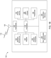
- FIG. 1B is a system diagram illustrating an example WTRU 102.
- the WTRU 102 may include a processor 118, a transceiver 120, a transmit/receive element 122, a speaker/microphone 124, a keypad 126, a display/touchpad 128, non-removable memory 130, removable memory 132, a power source 134, a global positioning system (GPS) chipset 136, and/or other peripherals 138, among others.
- GPS global positioning system
- the processor 118 may be a general purpose processor, a special purpose processor, a conventional processor, a digital signal processor (DSP), a plurality of microprocessors, one or more microprocessors in association with a DSP core, a controller, a microcontroller, Application Specific Integrated Circuits (ASICs), Field Programmable Gate Array (FPGA) circuits, any other type of integrated circuit (IC), a state machine, and the like.
- the processor 118 may perform signal coding, data processing, power control, input/output processing, and/or any other functionality that enables the WTRU 102 to operate in a wireless environment.
- the processor 118 may be coupled to the transceiver 120, which may be coupled to the transmit/receive element 122. While FIG. 1B depicts the processor 118 and the transceiver 120 as separate components, it will be appreciated that the processor 118 and the transceiver 120 may be integrated together in an electronic package or chip.
- the transmit/receive element 122 may be configured to transmit signals to, or receive signals from, a base station (e.g., the base station 114a) over the air interface 116.
- a base station e.g., the base station 114a
- the transmit/receive element 122 may be an antenna configured to transmit and/or receive RF signals.
- the transmit/receive element 122 may be an emitter/detector configured to transmit and/or receive IR, UV, or visible light signals, for example.
- the transmit/receive element 122 may be configured to transmit and/or receive both RF and light signals. It will be appreciated that the transmit/receive element 122 may be configured to transmit and/or receive any combination of wireless signals.
- the WTRU 102 may include any number of transmit/receive elements 122. More specifically, the WTRU 102 may employ MIMO technology. Thus, in one embodiment, the WTRU 102 may include two or more transmit/receive elements 122 (e.g., multiple antennas) for transmitting and receiving wireless signals over the air interface 116.
- the transceiver 120 may be configured to modulate the signals that are to be transmitted by the transmit/receive element 122 and to demodulate the signals that are received by the transmit/receive element 122.
- the WTRU 102 may have multi-mode capabilities.
- the transceiver 120 may include multiple transceivers for enabling the WTRU 102 to communicate via multiple RATs, such as NR and IEEE 802.11, for example.
- the processor 118 of the WTRU 102 may be coupled to, and may receive user input data from, the speaker/microphone 124, the keypad 126, and/or the display/touchpad 128 (e.g., a liquid crystal display (LCD) display unit or organic light-emitting diode (OLED) display unit).
- the processor 118 may also output user data to the speaker/microphone 124, the keypad 126, and/or the display/touchpad 128.
- the processor 118 may access information from, and store data in, any type of suitable memory, such as the non-removable memory 130 and/or the removable memory 132.
- the non-removable memory 130 may include random-access memory (RAM), read-only memory (ROM), a hard disk, or any other type of memory storage device.
- the removable memory 132 may include a subscriber identity module (SIM) card, a memory stick, a secure digital (SD) memory card, and the like.
- SIM subscriber identity module
- SD secure digital
- the processor 118 may access information from, and store data in, memory that is not physically located on the WTRU 102, such as on a server or a home computer (not shown).
- the processor 118 may receive power from the power source 134, and may be configured to distribute and/or control the power to the other components in the WTRU 102.
- the power source 134 may be any suitable device for powering the WTRU 102.
- the power source 134 may include one or more dry cell batteries (e.g., nickel-cadmium (NiCd), nickel-zinc (NiZn), nickel metal hydride (NiMH), lithium-ion (Li-ion), etc.), solar cells, fuel cells, and the like.
- the processor 118 may also be coupled to the GPS chipset 136, which may be configured to provide location information (e.g., longitude and latitude) regarding the current location of the WTRU 102.
- location information e.g., longitude and latitude
- the WTRU 102 may receive location information over the air interface 116 from a base station (e.g., base stations 114a, 114b) and/or determine its location based on the timing of the signals being received from two or more nearby base stations. It will be appreciated that the WTRU 102 may acquire location information by way of any suitable location-determination method while remaining consistent with an embodiment.
- the WTRU 102 may include a full duplex radio for which transmission and reception of some or all of the signals (e.g., associated with particular subframes for both the UL (e.g., for transmission) and DL (e.g., for reception) may be concurrent, simultaneous, or the like.
- the full duplex radio may include an interference management unit to reduce and or substantially eliminate self-interference via either hardware (e.g., a choke) or signal processing via a processor (e.g., a separate processor (not shown) or via processor 118).
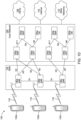
- Each of the gNBs 180a, 180b, 180c may be associated with a particular cell (not shown) and may be configured to handle radio resource management decisions, handover decisions, scheduling of users in the UL and/or DL, support of network slicing, dual connectivity, interworking between NR and E-UTRA, routing of user plane data towards User Plane Function (UPF) 184a, 184b, routing of control plane information towards Access and Mobility Management Function (AMF) 182a, 182b and the like. As shown in FIG. 1D , the gNBs 180a, 180b, 180c may communicate with one another over an Xn interface.
- UPF User Plane Function
- AMF Access and Mobility Management Function
- the AMF 182a, 182b may be connected to one or more of the gNBs 180a, 180b, 180c in the RAN 104 via an N2 interface and may serve as a control node.
- the AMF 182a, 182b may be responsible for authenticating users of the WTRUs 102a, 102b, 102c, support for network slicing (e.g., handling of different protocol data unit (PDU) sessions with different requirements), selecting a particular SMF 183a, 183b, management of the registration area, termination of non-access stratum (NAS) signaling, mobility management, and the like.
- PDU protocol data unit
- the AMF 182a, 182b may provide a control plane function for switching between the RAN 104 and other RANs (not shown) that employ other radio technologies, such as LTE, LTE-A, LTE-A Pro, and/or non-third generation partnership project (3GPP) access technologies such as WiFi.
- 3GPP non-third generation partnership project
- the SMF 183a, 183b may be connected to an AMF 182a, 182b in the CN 106 via an N11 interface.
- the SMF 183a, 183b may also be connected to a UPF 184a, 184b in the CN 106 via an N4 interface.
- the SMF 183a, 183b may select and control the UPF 184a, 184b and configure the routing of traffic through the UPF 184a, 184b.
- the SMF 183a, 183b may perform other functions, such as managing and allocating WTRU IP address, managing PDU sessions, controlling policy enforcement and QoS, providing DL data notifications, and the like.
- a PDU session type may be IP-based, non-IP based, Ethernet-based, and the like.
- the UPF 184a, 184b may be connected to one or more of the gNBs 180a, 180b, 180c in the RAN 104 via an N3 interface, which may provide the WTRUs 102a, 102b, 102c with access to packet-switched networks, such as the Internet 110, to facilitate communications between the WTRUs 102a, 102b, 102c and IP-enabled devices.
- the UPF 184, 184b may perform other functions, such as routing and forwarding packets, enforcing user plane policies, supporting multi-homed PDU sessions, handling user plane QoS, buffering DL packets, providing mobility anchoring, and the like.
- the CN 106 may facilitate communications with other networks.
- the CN 106 may include, or may communicate with, an IP gateway (e.g., an IP multimedia subsystem (IMS) server) that serves as an interface between the CN 106 and the PSTN 108.
- IP gateway e.g., an IP multimedia subsystem (IMS) server
- IMS IP multimedia subsystem
- the CN 106 may provide the WTRUs 102a, 102b, 102c with access to the other networks 112, which may include other wired and/or wireless networks that are owned and/or operated by other service providers.
- one or more, or all, of the functions described herein with regard to one or more of: WTRU 102a-d, Base Station 114a-b, eNode-B 160a-c, MME 162, SGW 164, PGW 166, gNB 180a-c, AMF 182a-b, UPF 184a-b, SMF 183a-b, DN 185a-b, and/or any other device(s) described herein, may be performed by one or more emulation devices (not shown).
- the emulation devices may be one or more devices configured to emulate one or more, or all, of the functions described herein.
- the emulation devices may be used to test other devices and/or to simulate network and/or WTRU functions.
- a category 4 may correspond to LBT with random back-off with a contention window of variable size that may draw a random number N within a contention window.
- the size of a contention window may be specified by a minimum value of N, a maximum value of N, or the like.
- a size of the contention window may also vary when drawing random number N.
- Table 1 Channel Access Priority Class ( p ) m p CW min, p CW max,p T m cot ,p Allowed CW p Sizes 1 1 3 7 2 ms ⁇ 3,7 ⁇ 2 1 7 15 3 ms ⁇ 7,15 ⁇ 3 3 15 63 8 or 10 ms ⁇ 15,31,63 ⁇ 4 7 15 1023 8 or 10 ms ⁇ 15,31,63,127,255,511,1023 ⁇
- an interlace resource allocation may be utilized for data channels only, a control channel may be transmitted using a licensed band, a control channel may be transmitted using a physical uplink control channel (PUCCH) in a licensed band, or the like.
- PUCCH physical uplink control channel
- NR numerology on unlicensed spectrum may be based on frequency such as 5 GHz, 37 GHz, 60 GHz, or the like.
- Configurations where NR-LAA is anchored to a legacy LTE carrier by DC and CA based aggregation with a 5G NR anchor may be utilized by standalone and non-standalone NR.
- a Golay modulator may apply a non-coherent, coherent, concatenation based, or an overlapping based technique to generate a Golay sequence.
- a Golay modulator may be realized using a channel code.
- UCI bits may be mapped to a set of interleaved subcarriers.
- Golay complementary pairs and sequences may be used for peak-to-average power mitigation or minimization, estimation of in-phase/quadrature (IQ) imbalance parameters, or channel estimation due to desirable properties.
- Golay sequences may be used in a single carrier physical (PHY) and low power SC PHY for a guard interval (GI), in a beamforming training (TRN) field, or the like.
- a sequence may have ideal APAC properties when
- 2 ⁇ a (0) (i.e., a constant) is true.
- An ideal sequence may include the property of being unimodal in every point in time.
- ISL integrated sidelobe level
- MF merit factor
- a sPUCCH may be transmitted over an unlicensed carrier, such as in NR standalone operation. Like NR licensed sPUCCH, some sequences may be transmitted to represent an acknowledgement (ACK), negative ACK (NACK), scheduling request (SR), reference signal (RS), or the like messages. When sPUCCH symbols are transmitted within a short period, high power transmission may be needed to increase symbol energy. Accordingly, sequences for sPUCCH in an unlicensed band may have low PAPR. However, constructing sequences with low PAPR for unlicensed bands may be difficult due to interlace structures as given in 200.
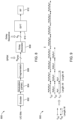
- FIG. 3 is a chart 300 of a PAPR distribution for sPUCCH Format 0 in MulteFire.
- sPUCCH for Format 0 SRs may utilize a cyclically-padded Zadoff-Chu sequence having undesirable PAPR properties. Additionally, this configuration may result in complexity at a receiver or transceiver due to multi or polyphases properties, such that elements of the sequence may be arbitrary or random complex numbers with unit amplitude.
- a sPUCCH configuration to control the PAPR of the sequence-based sPUCCH of interlaced waveforms in the unlicensed band and decrease receiver complexity by limiting a sequence alphabet constellation may be configured or utilized.
- Golay sequence based interlaces may be utilized, such as for sPUCCH X bit transmissions. In certain configurations, X may be 1-2 bits.
- the inverse discrete Fourier transform (IDFT) of one of the sequences of one of a quinary Golay complementary pair may be transmitted to signal control information, ACK, NACK, SR, RS(s), or the like in the frequency domain.
- IDFT inverse discrete Fourier transform
- the cluster size of an interlace for sPUCCH may be N rb subcarriers, the interlace may have N cluster , and the cluster may be separated by (k - 1)N rb subcarriers, where k is a non-negative integer.
- the transmitted quinary sequence in a Golay complementary pair of length of kN rb N cluster may follow an interlace structure.
- the elements of the sequence carried over the subcarriers may belong to the clusters that are in the constellation of QPSK, or there are N rb ⁇ N cluster symbols which are in a QPSK constellation, and the elements of the sequence that are not carried over the subcarriers belong to the clusters, or there are (k - 1)N rb ⁇ N cluster null symbols.
- the PAPR of the corresponding quinary Golay sequence may be less than a predetermined target that is difficult to maintain. For instance, a target of ⁇ 3 dB PAPR may be a stringent target for multiple cluster configurations but desirable since it may improve the coverage or range in the uplink and save power.
- FIG. 4 is a transmitter or a transceiver block diagram 400 for interlace based on a quinary Golay sequence 402 for control or PUCCH communications.
- An IDFT operation 404 may be performed on the 1 st cluster to N Cluster th with the output shifted by cyclic shift unit 406 of information input or signal 408.
- a quinary sequence used in a PUCCH interlace may be based on various operations. For instance, interlaces in a sPUCCH may utilize a unified property to generate Golay complementary pairs, varying phase shifts to achieve different constellations, or the like.
- FIG. 5 is a diagram 500 showing examples for sPUCCH interlaces.
- a Golay pair (c, d) of length N rb where the elements of the sequences may be in a QPSK constellation, may be obtained followed by calculating padding c, d with (k - 1)N rb null symbols and assignment to c', d'.
- ⁇ is the reverse of a
- a* is the conjugate of a.
- An interlace may utilize either e or f or a combination in frequency.
- a and b are a Golay complementary pair as (a, b), then, (a, b ⁇ *), ( ⁇ *, b ⁇ *), ( ⁇ *, b), (b, a) may also be Golay complementary pairs.
- sequences a, b may be generated to generate different quinary Golay complementary pairs.
- sequences a, b may be fixed and c, d may be changed based on a table, permutated based on various properties, or the like.
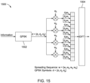
- a Set A of sequences 1902 and Set B of sequences 1904 may be utilized based on sequence index u.
- the cross correlation of the sequences in Set A and Set B may be low.
- the maximum normalized peak cross-correlation may be less than 0.75.
- Set A and Set B may comprise of sequences generated through any 30 rows of Table 3A and Table 3B, as long as the same rows in Table 3A and Table 3B, are selected (e.g., the first 30 rows in Table 3A and Table 3B may be selected).
- the WTRU may obtain the sequences from Set A and Set B, for instance gA u ⁇ C L ⁇ 1 and gB u ⁇ C L ⁇ 1 , where gA u and gB u may be a Golay complementary pair.
- a set of zero symbols may be padded to gA u and gB u , by zero-padding component 1906 resulting pA u ⁇ C L p ⁇ 1 and pB u ⁇ C L p ⁇ 1 , respectively.
- the number of zero symbols may be a function of the bandwidth parts, subcarrier spacing, operation bandwidth, or the like and may determine the gap between the clusters in frequency.
- the WTRU may determine another two spreading sequences at spreading component 1908, for instance sA ⁇ C L s ⁇ 1 and sB ⁇ C L s ⁇ 1 , for gA u and gB u , respectively, and sA and sB may be a Golay complementary pair.
- L s may depend on the operating bandwidth, numerology, or the like.
- Exemplary values of sA and sB are given in Table 4.
- the values of A, B, or C may imply the parameters of a clustered structure or an interlace in the frequency domain.
- the input of IDFT may be portioned into B clusters of size of A ⁇ 12, and the cluster may be separated by C ⁇ 12 tones in the frequency domain.
- sA and sB for 40 MHz configurations may be derived from sA and sB for 20 MHz configurations, by using one of the Golay construction methods in Property 1.
- sA for 40 MHz may be based on sA and sB for 20 MHz and sB for 40 MHz may be based on sA and -sB for 20 MHz.
- the padded sequences for instance pA u and pB u , may be spread with sA and sB as sA ⁇ pA u ⁇ C M b ⁇ 1 and sB ⁇ pB u ⁇ C M b ⁇ 1 .
- spread sequences may also be multiplied with unit-norm complex coefficients, for instance w 0 and w 1 , and the resulting sequences may be mapped to the input of IDFT transformation component 1910.
- Coherent detection may be configured such that the quinary Golay-based sequence has two interleaved sub-quinary Golay-based sequences.
- a reference sequence and modulated sequence with a QPSK symbol may be derived by obtaining a Golay pair (c, d) of length N rb/ 2.
- e w 1 a ⁇ c " + w 2 b ⁇ d "
- f w 1 b ⁇ * ⁇ c " ⁇ w 2 a ⁇ * ⁇ d "
- the interlace may use either e or f or a combination in frequency.
- w 1 or w 2 may be a QPSK symbol that carries a SR, ACK, NACK, SR, RS, or the like information.
- w 1 or w 2 may be a fixed symbol utilized for coherent detection at a receiver, transceiver, or the like.
- users may be separated by applying a cyclic shift to the output of an IDFT.
- FIG. 6 is a transmitter or a transceiver block diagram 600 for interlace based on a quinary Golay-based sequence.
- Input 602 may be an ACK, NACK, SR, RS, or the like utilized to generate a quinary Golay-based sequence.
- An IDFT operation 604 may be performed on the 1 st cluster to N Cluster th of the sequence(s) with the output shifted by cyclic shift unit 608 using information, such as a WTRU index, 606. Since w 1 or w 2 may be a QPSK symbol or fixed symbol, 600 may be a configuration to multiplex reference symbols and data symbols such that every other symbol in frequency may be fixed and function as pilots.
- FIG. 7 is a diagram 700 showing another example of sPUCCH interlace.
- w 1 may be a QPSK symbol and w 2 a reference signal or symbol.
- N RB 12
- N cluster 10
- k 10
- PAPR may be substantially low as the sequence may be one of the sequences in a quinary Golay pair.
- FIG. 8 is a transmitter or a transceiver block diagram 800 with a Golay modulator (GM) for quadrature phase shift keying (QPSK).
- GM Golay modulator
- QPSK quadrature phase shift keying
- UCI bits may be inputted to an encoder 802 and modulated at modulation component 804.
- a set of QPSK symbols, which may be a fragment of coded and QPSK modulated sequences after processing by fragmentation component 806, may be processed by GM 808 before IDFT operation by IDFT component 810.
- a GM may be a component taking an input of modulation symbols, such as N QPSK QPSK symbols, and output one of many sequences, such as a sequence of length N S , in a Golay complementary pair.
- Output of IDFT component 810 may be processed by radio frequency (RF) component 812.
- RF radio frequency
- the coefficient for the fourth subsequence may be -w 1 w 4 w 5 , or a factor of three variables and it multiplies d (0) .
- Coefficients at the nth iteration may have unit amplitude as
- 2 1.
- GM may be a component that sets coefficients of the subsequences of c (n+1) (i.e., c (0) and d (0) ) based on procedures given herein to QPSK symbols and related parity or redundant symbols derived based on the QPSK symbols to return c (n+1) as the output of GM.
- q i may be the ith QPSK symbol and p i the ith parity symbol.
- w 1 and w 2 may be set to q 1 and q 2 , respectively. This configuration may not require parity symbols as w 1 and w 2 may be chosen independently.
- GM1 may be capable of utilizing 3 QPSK symbols, and w 1 w 3 , w 2 w 3 , and w 1 w 4 may be set to q 1 , q 2 , and q 3 , respectively.
- GM1 may utilize 4 QPSK symbols, and w 1 w 3 w 5 , w 2 w 3 w 5 , w 1 w 4 w 5 and w 1 w 3 w 6 may be set to q 1 , q 2 , q 3 , and q 4 , respectively.
- parity symbols and QPSK symbols may be different.
- (n + 1) QPSK symbols may be supported for GM1 with the output of c (n) .
- Some of the QPSK symbols may be fixed to reduce complexity or to serve as reference symbols in frequency for channel estimation at a receiver.
- Step 8 conj(q(1))*conj(q(1))*q(2)*q(3)*q(4); % Parity Step 8.
- m [q(1) q(2) q(3) p1 q(4) p2 p3 p4]. ; Step 9.
- s kron(m, ones(M,1)) .* kron(ones(4,1),[c; d]); % Multiply the sequences and the symbols, C_(3) Step 10.
- t ifft(s(:),4096); % Transmitted signal, the IDFT size is 4096.
- any one of steps 1-10 may be skipped or additional steps performed, as desired.
- a Golay modulator may also be realized by using a channel code, such as Reed-Muller, Walsh, or the like, and constraining the channel code such that it includes the N - 1 monomials with the order of 2 where N may be the total number of monomial with the order of 2.
- a channel code such as Reed-Muller, Walsh, or the like
- the vector f may lead to vector [q 1 q 2 q 3 p 1 q 4 p 2 p 3 p 4 ] in Fig. 10 .
- FIG. 17 is a diagram of a Golay modulator using Reed-Muller 1700 where UCI information is processed by Reed-Muller component 1702, modulated by modulation component 1704, IDFT operated by IDFT component 1706, and processed by RF component 1708.
- Each element of [q 1 q 2 q 3 p 1 q 4 p 2 p 3 p 4 ] may modulate the Golay sequence, i.e. Golay A and Golay B, as in Fig. 17 .
- zeros may be added between modulated Golay A and Golay B sequences to generate interlaces.
- An error correction encoder may utilize a polar code where frozen bits or messages may be chosen such that the resulting codeword yields a low PAPR signal or waveform.
- rows 1-5 may be frozen by multiplying with zeros.
- 2nd and 3rd rows may be multiplied by 2 for QPSK or 1 for BPSK. This may be similar to the operation in Reed-Muller in Fig. 17 . Hence, by only changing the frozen bits, PAPR may be reduced.
- Each element of e [q 1 q 2 q 3 p 1 q 4 p 2 p 3 p 4 ] may modulate a Golay sequence, i.e. Golay A and Golay B, as in Fig. 17 . Similar to above, in a configuration, zeros may be added between modulated Golay A and Golay B sequences to generate interlaces.
- FIG. 18 is an example of a table for generating QPSK symbols for a Golay modulator with a polar encoder 1800.
- a recursive method may be utilized to generate Golay pair (c (n+1) , d (n+1) ) of length of 2N(M + N z )2 n at an nth iteration as follows:
- a GM may be a component that sets the coefficients of the subsequences of c (n+1) (i.e., s 11 , s 12 , s 21 , and s 22 ) based on procedures given herein to QPSK symbols and related parity or redundant symbols derived based on the QPSK symbols to return c (n+1) as the output of a GM operation.
- FIG. 12a is a transmitter
- q i may be the ith QPSK symbol and p i is the ith parity symbol.
- n 1, w 1 and w 2 may be set to q 1 and q 2 , respectively. Without parity symbols, w 1 and w 2 may be chosen independently.
- GM1 may support 3 QPSK symbols, where w 1 w 3 , w 2 w 3 , and w 1 w 4 may be set to q 1 , q 2 , and q 3 , respectively.
- GM1 may support 4 QPSK symbols, where w 1 w 3 w 5 , w 2 w 3 w 5 , w 1 w 4 w 5 , and w 1 w 3 w 6 may be set to q 1 , q 2 , q 3 , and q 4 , respectively.
- parity symbols and QPSK symbols may be different than the examples in Fig. 12a , 12b , or 12c .
- (n + 1) QPSK symbols may be supported for GM2 with the output of c (n) .
- Some QPSK symbols may be fixed to reduce complexity or serve as reference symbols in frequency for channel estimation at a receiver or transceiver.
- Sequence c and d may be up-sampled by u before the procedure to generate the Golay pair (c (n+1) , d (n+1) ) with GM2 and the new ⁇ may be set to B/u. This may result in interleaved QPSK and parity symbols in frequency.
- q 1 and q 3 may be fixed symbols, it may be possible generate reference symbols for each cluster in interlace, e.g., 3 RS for a single RB, PRB, or the like.
- FIG. 13 is a chart 1300 of a generated interlace by using GM2.
- the origination sequences are QPSK-based Golay pairs and the GM2 settings do not overlap the QPSK symbols
- the amplitude for each subcarrier in the interlace may be 1 in this configuration.
- GM2 may result in a quinary Golay sequence, in certain configurations the PAPR of the transmitted signal or waveform may be less than or equal to ⁇ 3dB or 10 log 10 2.
- QPSK symbols for GM2 may be fixed to generate a full RS for one interlace in a sPUCCH.
- GM1 and GM2 include coding with parity symbols, in certain configurations UCI may transmitted without further coding.
- a sequence carrying control information may be mapped to a set of interleaved subcarriers.
- a length-K sequence may be mapped to K subcarriers where each subcarrier may belong to a RB, PRB, or the like, and the RBs may be separated in frequency such that the separation, such as in terms of number of subcarriers, between consecutive RBs remains the same or constant.
- FIG. 14 is a diagram 1400 of an interleaved frequency division multiple access (IFDMA) based sPUCCH.
- IFDMA interleaved frequency division multiple access
- a 1st subcarrier of each of the K RBs may be allocated to PUCCH resources for 1 st WTRU 1402 while the 2nd subcarrier of each of the K RBs may be allocated to PUCCH resources for 2 nd WTRU 1404.
- K may be set to 12 and a sequence may be selected from the set of the 30 length-12 computer generated sequences.
- the index of the subcarrier within the RBs may be signaled to the WTRU explicitly, may be configured, or may be signaled to the WTRU implicitly.
- the offset value or subcarrier index may change in time, over a number of slots, over a number of subframes, or the like.
- sequences may be re-used for sPUCCH transmission with a Block Interleaved Frequency Division Multiple Access (B-IFDMA) waveform.
- B-IFDMA Block Interleaved Frequency Division Multiple Access
- any length-12 or other lengths may be utilized.
- a resulting sequence may be mapped to resource blocks on an interlace using a B-IFDMA waveform.
- a WTRU may be configured to select one base sequence and one cyclic shift to apply to the base sequence.
- the index of the base sequence and the cyclic shift amount may be signaled to the WTRU.
- the same resulting sequence, the base sequence after being cyclically shifted, may be mapped to available, allocated, all, etc., RBs on an interlace using the B-IFDMA waveform for repetition.
- the same resulting sequence, the base sequence after being cyclically shifted, may be mapped to available, allocated, all, etc., RBs on an interlace using the B-IFDMA waveform.
- the sequence on each RB, PRB, or the like may be multiplied with a coefficient.
- the WTRU may determine r u of length L.
- r u is zero padded based on an indicated value C which may be a function of subcarrier spacing and the operating bandwidth, such as 20 MHz, 40 MHz, and 80 MHz, and it may be spread as s ⁇ [r u 0].
- the spread vector may be multiplied with a complex coefficient w 1 and the resulting vector may be mapped to the subcarriers in frequency.
- FIG. 20A is a diagram showing a vector that may be circularly shifted to indicate control information, an ACK, NACK, SR, RS, or the like after an IDFT operation.
- NR sequences 2002 may be selected using an index, followed by a zero-padding component 2004, and spreading 2006 using s.
- an IDFT operation may be performed by IDFT component 2008 with the resulting vector circularly shifted by cyclic shift component 2010 to indicate control information, an ACK, NACK, SR, RS, or the like.
- a cyclic prefix may be added by CP+ component 2012.
- the coefficients that multiply the sequence on each RB, i.e., the vector of s, may be chosen to meet a criterion or predetermined condition.
- the criterion may be to reduce the PAPR or cubic metric (CM) of a signal or waveform.
- FIG. 20B is a diagram 2014 showing that a spreading sequence may be a function of the sequence index u, such as s u .
- Sequences component 2016 may utilize sequence index u and sequence B. to output s u .
- Sequence B may be generated through an optimization process. For this configuration, s u may be based on a given r u to minimize PAPR or a CM of the produced signal or waveform.
- the length of spreading sequences may be a function of bandwidth parts, subcarrier spacing, operating bandwidth, or the like. Referring again to the sequences in Table 2, coefficients which minimizes PAPR and CM may be given by Table 5A and 5B.
- a phase shift may be applied to spreading sequences without changes to the minimum PAPR value obtained in Table 5A.
- coefficients that multiply the sequence on each RB, PRB, or the like may be chosen such that a desired criterion or condition is met.
- the same base sequence may be mapped to available, allocated, all, etc. RBs on an interlace using the B-IFDMA waveform.
- the cyclic shift applied to the sequences on different RBs may be different.
- the cyclic shift applied may be a function of a parameter signaled to the WTRU, one or more parameters already known to the WTRU, a RB index, a PRB index, the base sequence index, a symbol number, a slot number, a subframe number, a frame number, or the like.
- the sequence on each RB may be multiplied with a coefficient.
- coefficients that multiply the sequence on each RB may be chosen such that a desired criterion or condition is met.
- one of the 30 base sequences may be mapped to one RB, PRB, or the like of an interlace after a cyclic shift.
- the base sequences mapped to the RBs of an interlace may be the same or different.
- An example is given in Table 6 where an interlace in B-IFDMA includes 10 RBs.
- Table 6 RB index 1 2 3 4 5 6 7 8 9 10 Sequence Index (u) 0 2 6 0 9 16 22 29 2 15
- the base sequences mapped to the RBs of an interlace may be subject to the same cyclic shift.
- the sequence on each RB may be multiplied with a coefficient.
- a sequence and RB/PRB combination, or which sequence is mapped to which RB, and the coefficient that multiplies each sequence may be searched with an algorithm so that a specific criterion may be met. For example, the search may find the sequence or RB combination and set of multipliers so that the resulting signal or waveform has low PAPR.
- the cyclic shift applied to the sequences on different RBs may be the same or different.
- the cyclic shift applied to a sequence may be a function of at least one of a parameter signaled to the WTRU, one or more parameters already known to the WTRU, a RB index, a base sequence index, a symbol number, a slot number, a subframe number, a frame number, or the like.
- the sequence and RB/PRB combinations may be specified in a table with a variable number of rows, such as 30 rows. In certain configurations, a combination may be used in one cell. To minimize inter-cell interference, it is desirable to prevent the same sequence being used on the same RB in different cells. For this configuration, the columns of a table may have distinct sequence indices. For example, the sample 2-row Table 7 may not meet this criterion because the same base sequences are mapped to RBs 2 and 5. The sample 2-row Table 8, however, may meet this criterion. In a directional transmission with beamforming, the index of the sequence or the index of the set of coefficients applied for to a given sequence may be used to transmit the beam index.
Landscapes
- Engineering & Computer Science (AREA)
- Signal Processing (AREA)
- Computer Networks & Wireless Communication (AREA)
- Physics & Mathematics (AREA)
- Discrete Mathematics (AREA)
- General Physics & Mathematics (AREA)
- Mathematical Physics (AREA)
- Quality & Reliability (AREA)
- Mobile Radio Communication Systems (AREA)
- Burglar Alarm Systems (AREA)
Applications Claiming Priority (5)
| Application Number | Priority Date | Filing Date | Title |
|---|---|---|---|
| US201862615815P | 2018-01-10 | 2018-01-10 | |
| US201862630592P | 2018-02-14 | 2018-02-14 | |
| US201862652506P | 2018-04-04 | 2018-04-04 | |
| EP19702161.1A EP3738242B1 (fr) | 2018-01-10 | 2019-01-09 | Structure de canal physique de contrôle montant courte (spucch) |
| PCT/US2019/012893 WO2019139983A1 (fr) | 2018-01-10 | 2019-01-09 | Structure de canal physique de contrôle montant courte (spucch) |
Related Parent Applications (2)
| Application Number | Title | Priority Date | Filing Date |
|---|---|---|---|
| EP19702161.1A Division EP3738242B1 (fr) | 2018-01-10 | 2019-01-09 | Structure de canal physique de contrôle montant courte (spucch) |
| EP19702161.1A Division-Into EP3738242B1 (fr) | 2018-01-10 | 2019-01-09 | Structure de canal physique de contrôle montant courte (spucch) |
Publications (2)
| Publication Number | Publication Date |
|---|---|
| EP4576636A2 true EP4576636A2 (fr) | 2025-06-25 |
| EP4576636A3 EP4576636A3 (fr) | 2025-10-01 |
Family
ID=65237190
Family Applications (2)
| Application Number | Title | Priority Date | Filing Date |
|---|---|---|---|
| EP25174975.0A Pending EP4576636A3 (fr) | 2018-01-10 | 2019-01-09 | Structure de canal physique de commande de liaison montante (spucch) court |
| EP19702161.1A Active EP3738242B1 (fr) | 2018-01-10 | 2019-01-09 | Structure de canal physique de contrôle montant courte (spucch) |
Family Applications After (1)
| Application Number | Title | Priority Date | Filing Date |
|---|---|---|---|
| EP19702161.1A Active EP3738242B1 (fr) | 2018-01-10 | 2019-01-09 | Structure de canal physique de contrôle montant courte (spucch) |
Country Status (6)
| Country | Link |
|---|---|
| US (3) | US12113620B2 (fr) |
| EP (2) | EP4576636A3 (fr) |
| KR (2) | KR20250044802A (fr) |
| CN (3) | CN111602356B (fr) |
| TW (2) | TWI711289B (fr) |
| WO (1) | WO2019139983A1 (fr) |
Families Citing this family (12)
| Publication number | Priority date | Publication date | Assignee | Title |
|---|---|---|---|---|
| US11363630B2 (en) * | 2018-03-01 | 2022-06-14 | Qualcomm Incorporated | Bandwidth part (BWP) configuration for subband access in new radio-unlicensed (NR-U) |
| WO2020000356A1 (fr) * | 2018-06-29 | 2020-01-02 | Panasonic Intellectual Property Corporation Of America | Appareil de transmission, appareil de réception, procédé de transmission, et procédé de réception |
| KR102116347B1 (ko) * | 2018-11-01 | 2020-05-28 | 영남대학교 산학협력단 | 필터뱅크 다중 반송파 기법을 위한 자원블록간 간섭 제거 방법 및 이를 이용한 장치 |
| CN114128175B (zh) | 2019-07-12 | 2025-10-14 | Lg电子株式会社 | 在无线通信系统中发送/接收信号的方法和装置 |
| KR102544448B1 (ko) | 2019-07-12 | 2023-06-20 | 엘지전자 주식회사 | 무선 통신 시스템에서 신호를 송수신하는 방법 및 장치 |
| CN110535613A (zh) * | 2019-08-16 | 2019-12-03 | 中兴通讯股份有限公司 | 信号处理方法、装置、设备及存储介质 |
| CN113875179A (zh) * | 2019-08-29 | 2021-12-31 | Oppo广东移动通信有限公司 | 信息处理方法和装置 |
| CN115396080B (zh) * | 2019-10-07 | 2024-06-14 | Oppo广东移动通信有限公司 | 一种在宽带系统中分配频率资源的方法 |
| US11316720B2 (en) * | 2020-01-13 | 2022-04-26 | Samsung Electronics Co., Ltd. | Apparatus and method for signaling of zero padding bins in fronthaul interface |
| CN114091378B (zh) * | 2021-11-19 | 2024-06-21 | 重庆邮电大学 | 非周期四相完美交叉z互补序列对信号的生成装置及方法 |
| US20240097844A1 (en) * | 2022-09-20 | 2024-03-21 | Telefonaktiebolaget Lm Ericsson (Publ) | Reference signalling for wireless communication |
| US12562754B2 (en) * | 2024-05-02 | 2026-02-24 | Qualcomm Incorporated | Single-index parity check for polar encoding |
Family Cites Families (24)
| Publication number | Priority date | Publication date | Assignee | Title |
|---|---|---|---|---|
| WO2010011083A2 (fr) * | 2008-07-22 | 2010-01-28 | 엘지전자 주식회사 | Procédé d'attribution de phich et de génération d'un signal dans un système a entrée multiple sortie multiple (mimo) basé sur des mots de code multiples lors de la transmission en liaison montante |
| US8467799B2 (en) | 2009-08-20 | 2013-06-18 | Samsung Electronics Co., Ltd. | Method and system for assigning physical uplink control channel (PUCCH) resources |
| KR101782645B1 (ko) * | 2010-01-17 | 2017-09-28 | 엘지전자 주식회사 | 무선 통신 시스템에서 상향링크 제어 정보 전송 방법 및 장치 |
| KR101241916B1 (ko) * | 2010-02-07 | 2013-03-11 | 엘지전자 주식회사 | 다중 안테나를 지원하는 무선 통신 시스템에서 하향링크 참조신호를 전송하는 방법 및 장치 |
| WO2011096646A2 (fr) | 2010-02-07 | 2011-08-11 | Lg Electronics Inc. | Procédé et appareil pour émettre un signal de référence descendant dans un système de communication sans fil prenant en charge plusieurs antennes |
| KR101285398B1 (ko) | 2010-09-08 | 2013-07-10 | 엘지전자 주식회사 | 무선 통신 시스템에서 제어 정보의 전송 방법 및 장치 |
| US20140029558A1 (en) | 2011-04-08 | 2014-01-30 | Nokia Siemens Networks Oy | Uplink Control Signalling in a Carrier Aggregation System |
| US10033505B2 (en) * | 2014-07-31 | 2018-07-24 | Qualcomm Incorporated | Transmission of uplink control channels over an unlicensed radio frequency spectrum band |
| US10129857B2 (en) | 2014-11-06 | 2018-11-13 | Qualcomm Incorporated | Band occupancy techniques for transmissions in unlicensed spectrum |
| US9918302B2 (en) * | 2014-12-12 | 2018-03-13 | Qualcomm Incorporated | Techniques for managing transmissions in an unlicensed radio frequency spectrum band |
| US10511427B2 (en) * | 2015-01-30 | 2019-12-17 | Qualcomm Incorporated | Uplink control channel for acknowledging increased number of downlink component carriers |
| ES3013564T3 (en) | 2015-12-07 | 2025-04-14 | Ericsson Telefon Ab L M | Uplink control channel configuration for unlicensed carriers |
| CN107046718B (zh) | 2016-02-05 | 2020-09-04 | 上海诺基亚贝尔股份有限公司 | 配置缩短的pucch的方法和装置 |
| US20170245263A1 (en) * | 2016-02-05 | 2017-08-24 | Mediatek Inc. | PUCCH Resource Allocation and Peak to Average Power Ratio Reduction in eLAA |
| MX2018009681A (es) | 2016-02-18 | 2018-09-11 | Ericsson Telefon Ab L M | Un metodo para determinar parametros para transmitir en un canal de control de enlace ascendente. |
| US20200287671A1 (en) * | 2016-03-04 | 2020-09-10 | Nokia Solutions And Networks Oy | Block-ifdma multiplexing scheme with flexible payload |
| US10524237B2 (en) | 2016-03-07 | 2019-12-31 | Samsung Electronics Co., Ltd. | Control signaling for supporting multiple services in advanced communication systems |
| EP3456137B1 (fr) * | 2016-05-12 | 2020-05-27 | Intel IP Corporation | Conception de canal physique d'accès aléatoire (prach) |
| WO2017217799A1 (fr) * | 2016-06-16 | 2017-12-21 | 엘지전자 주식회사 | Procédé d'émission et de réception d'un canal de commande physique de liaison montante dans un système de communication sans fil, et dispositif prenant en charge ce procédé |
| CN109891974B (zh) * | 2016-09-09 | 2023-03-21 | 株式会社Ntt都科摩 | 用户终端和无线通信方法 |
| WO2018050094A1 (fr) * | 2016-09-14 | 2018-03-22 | Mediatek Inc. | Pucch court dans des réseaux nr |
| WO2018160046A1 (fr) * | 2017-03-03 | 2018-09-07 | 엘지전자 주식회사 | Procédé et équipement d'utilisateur pour transmettre un préambule d'accès aléatoire, et procédé et station de base pour recevoir un préambule d'accès aléatoire |
| CN109391425B (zh) * | 2017-08-11 | 2020-10-16 | 电信科学技术研究院 | 一种信息的传输方法、终端及基站 |
| US10602506B2 (en) | 2017-09-28 | 2020-03-24 | Apple Inc. | Activation of secondary cell containing bandwidth parts |
-
2019
- 2019-01-09 KR KR1020257009396A patent/KR20250044802A/ko active Pending
- 2019-01-09 EP EP25174975.0A patent/EP4576636A3/fr active Pending
- 2019-01-09 WO PCT/US2019/012893 patent/WO2019139983A1/fr not_active Ceased
- 2019-01-09 US US16/960,937 patent/US12113620B2/en active Active
- 2019-01-09 CN CN201980007809.8A patent/CN111602356B/zh active Active
- 2019-01-09 EP EP19702161.1A patent/EP3738242B1/fr active Active
- 2019-01-09 CN CN202311020849.0A patent/CN117061068A/zh active Pending
- 2019-01-09 KR KR1020207021662A patent/KR102786925B1/ko active Active
- 2019-01-09 CN CN202311022646.5A patent/CN117061069A/zh active Pending
- 2019-01-10 TW TW108100985A patent/TWI711289B/zh not_active IP Right Cessation
- 2019-01-10 TW TW109135712A patent/TWI821606B/zh active
-
2023
- 2023-10-06 US US18/377,684 patent/US12244420B2/en active Active
-
2025
- 2025-01-17 US US19/028,983 patent/US20250167925A1/en active Pending
Also Published As
| Publication number | Publication date |
|---|---|
| US20250167925A1 (en) | 2025-05-22 |
| CN117061069A (zh) | 2023-11-14 |
| US12113620B2 (en) | 2024-10-08 |
| CN111602356B (zh) | 2023-08-18 |
| WO2019139983A1 (fr) | 2019-07-18 |
| EP4576636A3 (fr) | 2025-10-01 |
| KR102786925B1 (ko) | 2025-03-25 |
| TW201937887A (zh) | 2019-09-16 |
| EP3738242A1 (fr) | 2020-11-18 |
| CN111602356A (zh) | 2020-08-28 |
| TW202121862A (zh) | 2021-06-01 |
| US20200344099A1 (en) | 2020-10-29 |
| US20240063950A1 (en) | 2024-02-22 |
| KR20250044802A (ko) | 2025-04-01 |
| KR20200120620A (ko) | 2020-10-21 |
| EP3738242B1 (fr) | 2025-06-18 |
| TWI711289B (zh) | 2020-11-21 |
| TWI821606B (zh) | 2023-11-11 |
| CN117061068A (zh) | 2023-11-14 |
| US12244420B2 (en) | 2025-03-04 |
Similar Documents
| Publication | Publication Date | Title |
|---|---|---|
| US12244420B2 (en) | Short physical uplink control channel (sPUCCH) structure | |
| US12362882B2 (en) | Phase tracking reference signal transmission | |
| US12262383B2 (en) | Control channel for new radio | |
| EP3520294B1 (fr) | Conception des canaux de contrôle non-orthogonaux pour des systèmes de communication sans fil | |
| US11689307B2 (en) | Methods, apparatuses and systems directed to complementary sequence encoding and encoded complementary sequence transmissions | |
| WO2019160849A1 (fr) | Ordonnancement et transmission pour noma | |
| CN110603790A (zh) | 使用离散傅里叶变换扩展正交频分复用(dft-s-ofdm)波形的上行链路控制信道的发射分集 | |
| US20250030587A1 (en) | Low papr dmrs and low inter-cell interference for dft-spread ofdm | |
| WO2019035961A1 (fr) | Codage de données avec des séquences de golay | |
| WO2018175578A1 (fr) | Attribution de ressources pour canal de commande de liaison montante | |
| US12574929B2 (en) | Physical uplink control channel transmission | |
| WO2024206424A1 (fr) | Activation d'adaptation de débit pour réémission avec réservation de tonalité | |
| WO2020033295A1 (fr) | Procédés et procédures d'identification de wtru et de rétroaction pour noma | |
| WO2019143941A1 (fr) | Mises en œuvre de signaux de référence pour un accès multiple non orthogonal |
Legal Events
| Date | Code | Title | Description |
|---|---|---|---|
| PUAI | Public reference made under article 153(3) epc to a published international application that has entered the european phase |
Free format text: ORIGINAL CODE: 0009012 |
|
| STAA | Information on the status of an ep patent application or granted ep patent |
Free format text: STATUS: REQUEST FOR EXAMINATION WAS MADE |
|
| 17P | Request for examination filed |
Effective date: 20250508 |
|
| AC | Divisional application: reference to earlier application |
Ref document number: 3738242 Country of ref document: EP Kind code of ref document: P |
|
| AK | Designated contracting states |
Kind code of ref document: A2 Designated state(s): AL AT BE BG CH CY CZ DE DK EE ES FI FR GB GR HR HU IE IS IT LI LT LU LV MC MK MT NL NO PL PT RO RS SE SI SK SM TR |
|
| PUAL | Search report despatched |
Free format text: ORIGINAL CODE: 0009013 |
|
| AK | Designated contracting states |
Kind code of ref document: A3 Designated state(s): AL AT BE BG CH CY CZ DE DK EE ES FI FR GB GR HR HU IE IS IT LI LT LU LV MC MK MT NL NO PL PT RO RS SE SI SK SM TR |
|
| RIC1 | Information provided on ipc code assigned before grant |
Ipc: H04L 5/00 20060101AFI20250822BHEP |