EP4576871A1 - Kommunikationsverfahren und kommunikationsvorrichtung - Google Patents
Kommunikationsverfahren und kommunikationsvorrichtung Download PDFInfo
- Publication number
- EP4576871A1 EP4576871A1 EP23870355.7A EP23870355A EP4576871A1 EP 4576871 A1 EP4576871 A1 EP 4576871A1 EP 23870355 A EP23870355 A EP 23870355A EP 4576871 A1 EP4576871 A1 EP 4576871A1
- Authority
- EP
- European Patent Office
- Prior art keywords
- network unit
- configuration
- link
- information
- terminal device
- Prior art date
- Legal status (The legal status is an assumption and is not a legal conclusion. Google has not performed a legal analysis and makes no representation as to the accuracy of the status listed.)
- Pending
Links
Images



Classifications
-
- H—ELECTRICITY
- H04—ELECTRIC COMMUNICATION TECHNIQUE
- H04W—WIRELESS COMMUNICATION NETWORKS
- H04W40/00—Communication routing or communication path finding
- H04W40/02—Communication route or path selection, e.g. power-based or shortest path routing
- H04W40/22—Communication route or path selection, e.g. power-based or shortest path routing using selective relaying for reaching a BTS [Base Transceiver Station] or an access point
-
- H—ELECTRICITY
- H04—ELECTRIC COMMUNICATION TECHNIQUE
- H04W—WIRELESS COMMUNICATION NETWORKS
- H04W24/00—Supervisory, monitoring or testing arrangements
- H04W24/02—Arrangements for optimising operational condition
-
- H—ELECTRICITY
- H04—ELECTRIC COMMUNICATION TECHNIQUE
- H04W—WIRELESS COMMUNICATION NETWORKS
- H04W28/00—Network traffic management; Network resource management
- H04W28/02—Traffic management, e.g. flow control or congestion control
-
- H—ELECTRICITY
- H04—ELECTRIC COMMUNICATION TECHNIQUE
- H04W—WIRELESS COMMUNICATION NETWORKS
- H04W28/00—Network traffic management; Network resource management
- H04W28/02—Traffic management, e.g. flow control or congestion control
- H04W28/0268—Traffic management, e.g. flow control or congestion control using specific QoS parameters for wireless networks, e.g. QoS class identifier [QCI] or guaranteed bit rate [GBR]
-
- H—ELECTRICITY
- H04—ELECTRIC COMMUNICATION TECHNIQUE
- H04W—WIRELESS COMMUNICATION NETWORKS
- H04W28/00—Network traffic management; Network resource management
- H04W28/16—Central resource management; Negotiation of resources or communication parameters, e.g. negotiating bandwidth or QoS [Quality of Service]
- H04W28/24—Negotiating SLA [Service Level Agreement]; Negotiating QoS [Quality of Service]
-
- H—ELECTRICITY
- H04—ELECTRIC COMMUNICATION TECHNIQUE
- H04W—WIRELESS COMMUNICATION NETWORKS
- H04W76/00—Connection management
- H04W76/10—Connection setup
- H04W76/15—Setup of multiple wireless link connections
-
- H—ELECTRICITY
- H04—ELECTRIC COMMUNICATION TECHNIQUE
- H04W—WIRELESS COMMUNICATION NETWORKS
- H04W76/00—Connection management
- H04W76/20—Manipulation of established connections
-
- H—ELECTRICITY
- H04—ELECTRIC COMMUNICATION TECHNIQUE
- H04W—WIRELESS COMMUNICATION NETWORKS
- H04W76/00—Connection management
- H04W76/20—Manipulation of established connections
- H04W76/22—Manipulation of transport tunnels
-
- H—ELECTRICITY
- H04—ELECTRIC COMMUNICATION TECHNIQUE
- H04W—WIRELESS COMMUNICATION NETWORKS
- H04W88/00—Devices specially adapted for wireless communication networks, e.g. terminals, base stations or access point devices
- H04W88/02—Terminal devices
- H04W88/04—Terminal devices adapted for relaying to or from another terminal or user
-
- H—ELECTRICITY
- H04—ELECTRIC COMMUNICATION TECHNIQUE
- H04W—WIRELESS COMMUNICATION NETWORKS
- H04W92/00—Interfaces specially adapted for wireless communication networks
- H04W92/16—Interfaces between hierarchically similar devices
- H04W92/18—Interfaces between hierarchically similar devices between terminal devices
Definitions
- This application relates to the field of wireless communication, and more specifically, to a communication method and a communication apparatus.
- a sidelink user equipment-to-network relay (sidelink UE-to-Network Relay, SL U2N Relay) communication technology is proposed in new radio (new radio, NR).
- a remote user equipment (remote UE) can communicate with a base station via a relay user equipment (relay UE) located within a service range of a network device.
- the remote user equipment may alternatively directly communicate with the base station.
- a link for communication between the remote user equipment and the base station via the relay user equipment may be referred to as an indirect link, and a link for direct communication between the remote device and the base station may be referred to as a direct link.
- the base station is divided into a central unit (central unit, CU) and a distributed unit (distributed unit, DU).
- the DU is responsible for determining configurations corresponding to a radio bearer of the remote user equipment on the two links. However, when the two links exist between the DU and the remote user equipment, the DU may fail to correctly provide the configurations corresponding to the radio bearer.
- Embodiments of this application provide a communication method and a communication apparatus. According to the method, a configuration corresponding to a radio bearer can be correctly provided for a remote terminal device. This helps improve data transmission efficiency of the radio bearer.
- a communication method includes: A first network unit sends first information to a second network unit.
- the first information includes first indication information, the first indication information indicates a configuration type of a first radio bearer of a remote terminal device, and the configuration type is one of a first configuration type, a second configuration type, and a third configuration type.
- the first configuration type is that a radio bearer is configured on a first link
- the second configuration type is that a radio bearer is configured on a second link
- the third configuration type is that a radio bearer is configured on the first link and the second link
- the first link is a link between the second network unit and the remote terminal device
- the second link is a link through which the second network unit is connected to the remote terminal device via a relay terminal device.
- the first network unit receives configuration information from the second network unit.
- the configuration information includes a configuration of a first radio link control RLC bearer and/or a configuration of a second RLC bearer that correspond/corresponds to the first radio bearer, the configuration of the first RLC bearer is a configuration of an RLC bearer of the first radio bearer on the first link, and the configuration of the second RLC bearer is a configuration of an RLC bearer of the first radio bearer on the second link.
- the first network unit sends the configuration information to the remote terminal device.
- the first network unit may be a gNB-CU
- the second network unit may be a gNB-DU
- the first link may be a direct link between the gNB-DU and the remote terminal device
- the second link may be an indirect link between the gNB-DU and the remote terminal device.
- the remote terminal device On the first link, the remote terminal device may communicate with the second network unit through a Uu interface.
- the remote terminal device may communicate with the second network unit via the relay terminal device.
- the first information may be a second context modification request message that is of the remote terminal device and that is sent by the gNB-CU to the gNB-DU.
- the first network unit may indicate the configuration type of the first radio bearer to the second network unit, so that the second network unit determines whether to provide the configuration of the first RLC bearer corresponding to the first radio bearer, to correctly provide the configuration of the first radio bearer for the remote terminal device.
- the remote terminal device may be connected to a base station through the two links, and the radio bearer is configured on the direct link, the indirect link, or the two links, so that coverage and radio resource utilization of an entire mobile network system can be improved, a delay can be reduced, and system performance can be improved.
- the method further includes: The first network unit determines the configuration type of the first radio bearer.
- the third configuration type includes that the radio bearer is configured to perform packet data convergence protocol duplication PDCP duplication or perform packet data convergence protocol split PDCP split.
- a data packet may be transmitted/delivered to an RLC entity/bearer on which a link is located, the data packet is duplicated once, and a data packet obtained through duplication is transmitted to an RLC entity/bearer on which another link is located.
- each data packet is randomly transmitted/delivered to an RLC entity/bearer of one of the links.
- a data transmission rate of the radio bearer can be increased, and data transmission reliability of the radio bearer can be improved.
- the method further includes: The first network unit sends second information to the second network unit and/or the remote terminal device.
- the second information indicates the second network unit to perform multi-path configuration or switching configuration for the remote terminal device.
- the second information may be multi-path (multi-path) indication information.
- the second information indicates the second network unit and/or the remote terminal device to perform multi-path configuration or switching configuration, so that the second network unit and the remote terminal device can perform correct configuration.
- the second network unit may establish only a new link to the remote terminal device, and may communicate with the remote terminal device through a plurality of links.
- the second information indicates to disconnect an original link between the second network unit and the remote terminal device, and establish a new link.
- the first information further includes second indication information, and the second indication information indicates to set up or reconfigure the second RLC bearer for the remote terminal device, or the second indication information indicates the second network unit to determine the configuration of the second RLC bearer.
- the first network unit may send the second indication information to the second network unit, to indicate the second network unit to set up or reconfigure the second RLC bearer corresponding to the first radio bearer, or indicate the second network unit to determine the configuration of the second RLC bearer.
- the first network unit sends first quality of service QoS information and/or second QoS information to the second network unit, the first QoS information indicates that the configuration of the first RLC bearer needs to meet the first QoS information, and the second QoS information indicates that the configuration of the second RLC bearer needs to meet the second QoS information.
- the method further includes: The first network unit sends a configuration of a sidelink relay adaptation protocol SRAP layer on the second link to the remote terminal device.
- the configuration of the SRAP layer includes a mapping relationship between the first radio bearer and the second RLC bearer.
- the first network unit may send the configuration of the SRAP layer to the remote terminal device, so that the remote terminal device configures the SRAP layer. This helps transmit data of the radio bearer on the correct second RLC bearer.
- the first network unit is a central unit CU
- the second network unit is a distributed unit DU.
- a communication method includes: A second network unit receives first information from a first network unit.
- the first information includes first indication information, the first indication information indicates a configuration type of a first radio bearer of a remote terminal device, and the configuration type of the first radio bearer is one of a first configuration type, a second configuration type, and a third configuration type.
- the first configuration type is that a radio bearer is configured on a first link
- the second configuration type is that a radio bearer is configured on a second link
- the third configuration type is that a radio bearer is configured on the first link and the second link
- the first link is a link between the second network unit and the remote terminal device
- the second link is a link through which the second network unit is connected to the remote terminal device via a relay terminal device.
- the second network unit determines, based on the first indication information, whether to provide a configuration of a first RLC bearer corresponding to the first radio bearer.
- the configuration of the first RLC bearer is a configuration of an RLC bearer of the first radio bearer on the first link.
- the second network unit sends configuration information to the first network unit. When the second network unit determines to provide the configuration of the first RLC bearer, the configuration information includes the configuration of the first RLC bearer.
- the first network unit may be a gNB-CU
- the second network unit may be a gNB-DU
- the first link may be a direct link between the gNB-DU and the remote terminal device
- the second link may be an indirect link between the gNB-DU and the remote terminal device.
- the remote terminal device On the first link, the remote terminal device may communicate with the second network unit through a Uu interface.
- the remote terminal device may communicate with the second network unit via the relay terminal device.
- the first information may be a second context modification request message that is of the remote terminal device and that is sent by the gNB-CU to the gNB-DU.
- the second network unit may determine, based on the configuration type of the first radio bearer, whether to provide the configuration of the first RLC bearer corresponding to the first radio bearer, to correctly provide the configuration of the first radio bearer for the remote terminal device. This helps improve data transmission efficiency of the radio bearer of the remote terminal device.
- the remote terminal device may be connected to a base station through the two links, and the radio bearer is configured on the direct link, the indirect link, or the two links, so that coverage and radio resource utilization of an entire mobile network system can be improved, a delay can be reduced, and system performance can be improved.
- the third configuration type includes that the radio bearer is configured to perform PDCP duplication or PDCP split.
- the method further includes: The second network unit receives second information from the second network unit. The second information indicates to perform multi-path configuration or switching configuration for the remote terminal device.
- the first information further includes second indication information.
- the second indication information indicates the second network unit to set up or reconfigure a second RLC bearer for the remote terminal device, or the second indication information indicates the second network unit to determine a configuration of the second RLC bearer.
- the configuration of the second RLC bearer is a configuration of an RLC bearer corresponding to the first radio bearer on the second link.
- the configuration information further includes the configuration of the second RLC bearer.
- the method further includes: The second network unit receives first QoS information and/or second QoS information from the second network unit.
- the first QoS information indicates that the configuration of the first RLC bearer needs to meet the first QoS information
- the second QoS information indicates that the configuration of the second RLC bearer needs to meet the second QoS information.
- the first network unit is a CU
- the second network unit is a DU
- a communication method includes: A remote terminal device receives configuration information from a first network unit via a second network unit.
- the configuration information includes a configuration of a first RLC bearer and/or a configuration of a second RLC bearer that correspond/corresponds to a first radio bearer of the remote terminal device, the configuration of the first RLC bearer is a configuration of an RLC bearer of the first radio bearer on a first link, the configuration of the second RLC bearer is a configuration of an RLC bearer of the first radio bearer on a second link, the first link is a link between the second network unit and the remote terminal device, the second link is a link through which the second network unit is connected to the remote terminal device via a relay terminal device, and a configuration type of the first radio bearer is one of a first configuration type, a second configuration type, and a third configuration type.
- the first configuration type is that a radio bearer is configured on the first link
- the second configuration type is that a radio bearer is configured on the second link
- the third configuration type is that a radio bearer is configured on the first link and the second link.
- the remote terminal device sets up the first RLC bearer and/or the second RLC bearer based on the configuration information.
- the first network unit may be a gNB-CU
- the second network unit may be a gNB-DU
- the first link may be a direct link between the gNB-DU and the remote terminal device
- the second link may be an indirect link between the gNB-DU and the remote terminal device.
- the remote terminal device On the first link, the remote terminal device may communicate with the second network unit through a Uu interface.
- the remote terminal device may communicate with the second network unit via the relay terminal device.
- the remote terminal device may receive correct configuration information, to configure the radio bearers.
- the method further includes: The remote terminal device receives second information from the first network unit.
- the second information indicates to perform multi-path configuration or switching configuration.
- the method further includes: The remote terminal device receives a configuration that is of an SRAP layer on the second link and that is sent by the first network unit.
- the configuration of the SRAP layer includes a mapping relationship between the first radio bearer and the second RLC bearer.
- the first network unit is a CU
- the second network unit is a DU
- a communication method includes: A first network unit receives first configuration information from a third network unit, and sends the first configuration information to a fourth network unit.
- the first configuration information is for configuring a radio bearer of a remote terminal device on a third link, and the third link is a link between the remote terminal device and the third network unit.
- the first network unit receives third information from the fourth network unit.
- the third information includes the first configuration information and second configuration information
- the second configuration information is for configuring the radio bearer of the remote terminal device on a fourth link
- the fourth link is a link between the remote terminal device and the fourth network unit.
- the remote terminal device communicates with the third network unit on the third link via a relay terminal device.
- the remote terminal device communicates with the third network unit on the fourth link via a relay terminal device.
- the first network unit may be a gNB-CU
- the third network unit may be a gNB-DU 1
- the fourth network unit may be a gNB-DU 2.
- the third link may be a communication link between the remote terminal device and the gNB-DU 1
- the third link may be a communication link between the remote terminal device and the gNB-DU 2
- there is at least one indirect link in the third link and the fourth link namely, a link for communicating with a DU via the relay terminal device.
- the third link on a third network unit side may be a direct link, or may be an indirect link.
- the first network unit may receive the first configuration information sent by the third network unit and the second configuration information sent by the fourth network unit, but the first network unit cannot parse the two pieces of configuration information. Consequently, only one piece of configuration information may be sent to the remote terminal device. In other words, the remote terminal device may fail to receive complete configuration information of the two links, and consequently cannot correctly configure the radio bearer.
- the first network unit may send the first configuration information of the third network unit to the fourth network unit, to receive the third information including the first configuration information and the second configuration information from the fourth network unit, so as to send a complete configuration of the radio bearer to the remote terminal device.
- the method further includes: The first network unit sends first indication information to the third network unit.
- the first indication information indicates the third network unit to determine the first configuration information.
- the first network unit sends second indication information to the fourth network unit.
- the second indication information indicates the fourth network unit to determine the second configuration information.
- the first network unit may separately send the indication information to the third network unit and the fourth network unit, to separately indicate the third network unit and the fourth network unit to provide the first configuration information and the second configuration information.
- the first configuration information includes a configuration corresponding to the radio bearer of the remote terminal device on the third link
- the second configuration information includes a configuration corresponding to the radio bearer of the remote terminal device on the fourth link.
- the method further includes: The first network unit determines that the third network unit or the fourth network unit is a primary network unit, or the first network unit determines that the third link or the fourth link is a primary link. Alternatively, the first network unit determines that the third network unit or the fourth network unit is a secondary network unit, or the first network unit determines that the third link or the fourth link is a secondary link.
- the first network unit may select one of the third network unit and the fourth network unit as the primary network unit or the secondary network unit, or the first network unit may select one of the third link and the fourth link as the primary link or the secondary link.
- the first network unit always sends, to the primary network unit, configuration information generated by the secondary network unit, and the primary network unit generates the third information and sends the third information to the first network unit.
- the first network unit always sends, to the secondary network unit, configuration information generated by the primary network unit, and the secondary network unit generates the third information and sends the third information to the first network unit.
- the first network unit always sends, to a network unit on a secondary link side, configuration information generated by a network unit on a primary link side, and the network unit on the secondary link side generates the third information and sends the third information to the first network unit.
- the first network unit always sends, to a network unit on a primary link side, configuration information generated by a network unit on a secondary link side, and the network unit on the primary link side generates the third information and sends the third information to the first network unit.
- the first network unit sends fifth information to the third network unit or the fourth network unit.
- the fifth information indicates that the third network unit or the fourth network unit is the primary network unit, or the fifth information indicates that the third link or the fourth link is the primary link.
- the fifth information indicates that the third network unit or the fourth network unit is the secondary network unit, or the fifth information indicates that the third link or the fourth link is the secondary link.
- the method further includes: The first network unit sends sixth information to the third network unit and the fourth network unit.
- the sixth information indicates to perform multi-path configuration or switching configuration for the remote terminal device.
- the first network unit is a CU
- the third network unit is a first DU
- the fourth network unit is a second DU.
- a communication method includes: A fourth network unit receives first configuration information from a third network unit.
- the first configuration information is for configuring a radio bearer of a remote terminal device on a third link, and the third link is a link through which the third network unit is connected to the remote terminal device.
- the fourth network unit sends third information to a first network unit.
- the third information includes the first configuration information and second configuration information
- the second configuration information is for configuring the radio bearer of the remote terminal device on a fourth link
- the fourth link is a link between the fourth network unit and the remote terminal device.
- the remote terminal device communicates with the third network unit on the third link via a relay terminal device.
- the remote terminal device communicates with the third network unit on the fourth link via a relay terminal device.
- the first network unit may receive the first configuration information sent by the third network unit and the second configuration information sent by the fourth network unit, but the first network unit cannot parse the two pieces of configuration information. Consequently, only one piece of configuration information may be sent to the remote terminal device. In other words, the remote terminal device may fail to receive complete configuration information of the two links, and consequently cannot correctly configure the radio bearer.
- the fourth network unit may receive the first configuration information from the third network unit, and generate the third information including the first configuration information and the second configuration information, to send a complete configuration of the radio bearer to the remote terminal device.
- the method further includes: The fourth network unit receives first indication information from the first network unit.
- the first indication information indicates the fourth network unit to determine the second configuration information.
- the method further includes: The fourth network unit receives fifth information from the first network unit.
- the fifth information indicates that the fourth network unit is a primary network unit, or the fifth information indicates that the fourth link is a primary link.
- the fifth information indicates that the fourth network unit is a secondary network unit, or the fifth information indicates that the fourth link is a secondary link.
- the first network unit is a CU
- the third network unit is a first DU
- the fourth network unit is a second DU.
- a communication method includes: A remote terminal device receives fourth information from a first network unit.
- the fourth information includes first configuration information and second configuration information, the first configuration information is for configuring a radio bearer of the remote terminal device on a third link, the second configuration information is for configuring the radio bearer of the remote terminal device on a fourth link, the third link is a link between the remote terminal device and a third network unit, and the fourth link is a link through which the remote terminal device is connected to a fourth network unit via a relay terminal device.
- the method further includes: The remote terminal device receives sixth information from the first network unit.
- the sixth information indicates to perform multi-path configuration or switching configuration.
- the method further includes:
- the first configuration information includes configurations of one or more third RLC bearers on the third link, and the second configuration information includes configurations of one or more fourth RLC bearers on the fourth link.
- the method further includes: The remote terminal device receives a configuration that is of an SRAP layer on the fourth link and that is sent by the first network unit.
- the configuration of the SRAP layer includes a mapping relationship between each radio bearer of the remote terminal device and the one or more fourth RLC bearers.
- the first network unit is a CU
- the third network unit is a first DU
- the fourth network unit is a second DU.
- the first information indicates the second network unit to provide a configuration of an RLC bearer corresponding to the first radio bearer, and the configuration of the RLC bearer is related to the configuration type of the first radio bearer.
- the first network unit receives configuration information from the second network unit.
- the configuration information includes the configuration of the RLC bearer.
- the first network unit sends the configuration information to the remote terminal device.
- the first radio bearer may correspond to the first RLC bearer and the second RLC bearer.
- the first information includes first indication information, and the first indication information indicates the configuration type of the first radio bearer.
- the configuration of the RLC bearer includes the configuration of the first RLC bearer, and the first RLC bearer is configured on the first link.
- the first information includes first indication information
- the first indication information is used by the second network unit to determine whether the configuration of the first RLC bearer needs to be provided.
- the configuration of the RLC bearer includes the configuration of the first RLC bearer, the first RLC bearer is set on the first link, the first information includes first indication information, and the first indication information indicates the second network unit to determine the configuration of the first RLC bearer.
- the configuration of the RLC bearer includes the configuration of the second RLC bearer
- the second RLC bearer is set on the first link
- the first information further includes second indication information
- the second indication information indicates the second network unit to determine the configuration of the second RLC bearer.
- a communication method includes: A first network unit sends first information to a second network unit.
- the first information includes first indication information, the first indication information indicates the second network unit to determine a configuration of a first radio link control RLC bearer, the first RLC bearer is an RLC bearer corresponding to a first radio bearer on a first link, and the first link is a link between the second network unit and a remote terminal device.
- the first network unit receives configuration information from the second network unit.
- the configuration information includes the configuration of the first RLC bearer corresponding to the first radio bearer.
- the first network unit sends the configuration information to the remote terminal device.
- the first indication information indicates that the first radio bearer is configured on the first link.
- the method further includes: The first network unit determines that the first radio bearer is configured on the first link.
- the method further includes: The first network unit sends second information to the second network unit and/or the remote terminal device.
- the second information indicates the second network unit to perform multi-path configuration or switching configuration for the remote terminal device.
- the first information further includes second indication information
- the second indication information indicates the second network unit to determine a configuration of a second RLC bearer corresponding to the first radio bearer
- the configuration of the second RLC bearer is an RLC bearer on a link between the remote terminal device and a relay terminal device
- the remote terminal device is connected to the second network unit via the relay terminal device.
- a communication system includes a first network unit, a second network unit, and a remote terminal device.
- the first network unit is configured to perform the communication method in any possible implementation of the first aspect
- the second network unit is configured to perform the communication method in any possible implementation of the second aspect
- the remote terminal device is configured to perform the communication method in any possible implementation of the third aspect.
- a communication apparatus may include a module or a unit configured to implement any one of the first aspect or the fourth aspect and the possible implementations of the first aspect or the fourth aspect.
- a communication apparatus may include a module or a unit configured to implement any one of the second aspect or the fifth aspect and the possible implementations of the second aspect or the fifth aspect.
- a communication apparatus may include a module or a unit configured to implement any one of the third aspect or the sixth aspect and the possible implementations of the third aspect or the sixth aspect.
- a computer-readable storage medium stores a computer program.
- the computer program When the computer program is run on a computer, the computer is enabled to perform the communication method according to any one of the first aspect or the fourth aspect and the possible implementations of the first aspect or the fourth aspect, perform the communication method according to any one of the second aspect or the fifth aspect and the possible implementations of the second aspect or the fifth aspect, or perform the communication method according to any one of the third aspect or the sixth aspect and the possible implementations of the third aspect or the sixth aspect.
- a computer program product includes computer program instructions.
- the computer is enabled to perform the communication method according to any one of the first aspect or the fourth aspect and the possible implementations of the first aspect or the fourth aspect, perform the communication method according to any one of the second aspect or the fifth aspect and the possible implementations of the second aspect or the fifth aspect, or perform the communication method according to any one of the third aspect or the sixth aspect and the possible implementations of the third aspect or the sixth aspect.
- a communication apparatus includes at least one processor.
- the at least one processor is configured to execute a computer program or instructions stored in a memory, to perform the communication method according to any one of the first aspect or the fourth aspect and the possible implementations of the first aspect or the fourth aspect, perform the communication method according to any one of the second aspect or the fifth aspect and the possible implementations of the second aspect or the fifth aspect, or perform the communication method according to any one of the third aspect or the sixth aspect and the possible implementations of the third aspect or the sixth aspect.
- the terminal device in embodiments of this application may be a user equipment (user equipment, UE), an access terminal, a subscriber unit, a subscriber station, a mobile station, a remote station, a remote terminal, a mobile device, a user terminal, a wireless communication device, a user agent, or a user apparatus.
- UE user equipment
- the terminal in embodiments of this application may be a mobile phone (mobile phone), a tablet computer (pad), a computer having a wireless transceiver function, a virtual reality (virtual reality, VR) terminal, an augmented reality (augmented reality, AR) terminal, a wireless terminal in industrial control (industrial control), a wireless terminal in self driving (self driving), a wireless terminal in remote medical (remote medical), a wireless terminal in a smart grid (smart grid), a wireless terminal in transportation safety (transportation safety), a wireless terminal in a smart city (smart city), a wireless terminal in a smart home (smart home), a cellular phone, a cordless phone, a session initiation protocol (session initiation protocol, SIP) phone, a wireless local loop (wireless local loop, WLL) station, a personal digital assistant (personal digital assistant, PDA), a handheld device having a wireless communication function, a computing device or another processing device connected to a wireless modem, a vehicle-mounted device, a wearable device,
- the wearable device may also be referred to as a wearable intelligent device, and is a generic term for wearable devices such as glasses, gloves, watches, clothes, and shoes that are developed by applying wearable technologies to intelligent designs of daily wear.
- the wearable device is a portable device that can be directly worn on the body or integrated into clothes or an accessory of a user.
- the wearable device is not only a hardware device, but also implements a powerful function through software support, data exchange, and cloud interaction.
- wearable intelligent devices include full-featured and large-sized devices that can implement all or a part of functions without depending on smartphones, for example, smart watches or smart glasses, and include devices that dedicated to only one type of application function and need to collaboratively work with other devices such as smartphones, for example, various smart bands or smart jewelry for monitoring physical signs.
- the terminal device may alternatively be a terminal device in an internet of things (internet of things, IoT) system.
- IoT internet of things
- a main technical feature of the IoT is connecting a thing to a network by using a communication technology, to implement an intelligent network for interconnection between a person and a machine or between one thing and another.
- a specific form of the terminal device is not limited in this application.
- the terminal device may be an apparatus configured to implement a function of the terminal device, or may be an apparatus that can support the terminal device in implementing the function, for example, a chip system.
- the apparatus may be mounted in the terminal.
- the chip system may be formed by a chip, or may include the chip and another discrete component.
- the network device in embodiments of this application may be any device with a wireless transceiver function.
- the device includes but is not limited to an evolved NodeB (evolved NodeB, eNB), a radio network controller (radio network controller, RNC), a NodeB (NodeB, NB), a base station controller (base station controller, BSC), a base transceiver station (base transceiver station, BTS), a home base station (for example, a home evolved NodeB, or a home NodeB, HNB), a baseband unit (baseband unit, BBU), an access point (access point, AP) in a wireless fidelity (wireless fidelity, Wi-Fi) system, a wireless relay node, a wireless backhaul node, a transmission point (transmission point, TP), a transmission and reception point (transmission and reception point, TRP), or the like; or may be a gNB or a transmission point (TRP or TP) in a 5G such as
- a gNB may include a central unit (central unit, CU) and a DU.
- the gNB may further include an active antenna unit (active antenna unit, AAU for short).
- the CU implements some functions of the gNB, and the DU implements some functions of the gNB.
- the CU is responsible for processing a non-real-time protocol and service, and implements functions of a radio resource control (radio resource control, RRC) layer and a packet data convergence protocol (packet data convergence protocol, PDCP) layer.
- RRC radio resource control
- PDCP packet data convergence protocol
- the DU is responsible for processing a physical layer protocol and a real-time service, and implements functions of a radio link control (radio link control, RLC) layer, a media access control (media access control, MAC) layer, and a physical (physical, PHY) layer.
- RLC radio link control
- MAC media access control
- PHY physical (physical, PHY) layer.
- the AAU implements some physical layer processing functions, radio frequency processing, and a function related to an active antenna.
- Information at the RRC layer eventually becomes information at the PHY layer, or is converted from information at the PHY layer. Therefore, in this architecture, it may also be considered that higher layer signaling, such as RRC layer signaling, may be sent by the DU or sent by the DU and the AAU.
- the network device may be a device including one or more of a CU node, a DU node, and an AAU node.
- the CU may be classified into a network device in an access network (radio access network, RAN), or the CU may be classified into a network device in a core network (core network, CN). This is not limited in this application.
- the network device may be an apparatus configured to implement a function of the network device, or may be an apparatus that can support the network device in implementing the function, for example, a chip system.
- the apparatus may be mounted in the network device.
- the technical solutions provided in this application may be applied to various communication systems, for example, a 5th generation (5th generation, 5G) or new radio (new radio, NR) system, a long term evolution (long term evolution, LTE) system, an LTE frequency division duplex (frequency division duplex, FDD) system, and an LTE time division duplex (time division duplex, TDD) system.
- 5G 5th generation
- NR new radio
- LTE long term evolution
- LTE frequency division duplex frequency division duplex
- FDD frequency division duplex
- TDD time division duplex
- the technical solutions provided in this application may be further applied to a future communication system, for example, a 6th generation mobile communication system.
- the technical solutions provided in this application may be further applied to device-to-device (device-to-device, D2D) communication, vehicle-to-everything (vehicle-to-everything, V2X) communication, machine-to-machine (machine-to-machine, M2M) communication, machine type communication (machine type communication, MTC), an internet of things (internet of things, IoT) communication system, or another communication system.
- D2D device-to-device
- V2X vehicle-to-everything
- machine-to-machine machine-to-machine
- M2M machine type communication
- MTC machine type communication
- IoT internet of things
- this application may be applied to an independently deployed 5G or LTE system, or may be applied to a non-independently deployed 5G or LTE system, for example, a DC scenario, including evolved universal terrestrial radio access-new radio dual connectivity (evolved universal terrestrial radio access-NR dual connectivity, EN-DC) or the like, and a carrier aggregation (carrier aggregation, CA) scenario.
- DC scenario including evolved universal terrestrial radio access-new radio dual connectivity (evolved universal terrestrial radio access-NR dual connectivity, EN-DC) or the like, and a carrier aggregation (carrier aggregation, CA) scenario.
- CA carrier aggregation
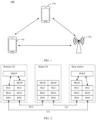
- FIG. 1 is a diagram of a communication system 100 applicable to an embodiment of this application.
- the communication system 100 may include at least one remote UE 110, at least one relay UE 120, and a network device 130.
- the remote UE 110 may communicate with the network device 130 through both a direct link and an indirect link (or referred to as a relay link).
- the remote UE 110 may communicate with the network device 130 through a Uu interface.
- the remote UE 110 may communicate with the network device 130 via the relay UE 120.
- the remote UE 110 may communicate with the relay UE 120 through a PC5 interface corresponding to a sidelink, or may communicate with the relay UE 120 through a non-3GPP (non-3GPP) link.
- the remote UE 110 may receive and send same or different data through both the two links, to improve a throughput rate and reliability of data receiving and sending.
- a UE in addition to directly communicating with a network device (for example, a base station), a UE may communicate with the base station via another UE.
- a relay UE may serve as a relay of a remote UE, so that the remote UE can communicate with the base station via the relay UE.
- This technology is referred to as a sidelink user equipment-to-network relay (sidelink UE-to-Network relay, SL U2N relay) technology, or may be referred to as a relay (relay) technology.
- the remote user equipment may also be referred to as a remote terminal device, and the relay user equipment may also be referred to as a relay terminal device.
- the relay terminal device may be a terminal device that provides network access for the remote terminal device, and the relay terminal device provides a relay service for the remote terminal device.
- the relay service may include: Information sent by the remote terminal device to the network device may be forwarded by the relay terminal device to the network device, and information sent by the network device to the remote terminal device may also be forwarded by the relay terminal device to the remote terminal device.
- two terminal apparatuses may directly communicate with each other without using a network device. This communication manner is referred to as sidelink (sidelink) communication.
- a link between the two terminal apparatuses is referred to as a sidelink, for example, the communication link between the remote terminal device 110 and the relay terminal device 120.
- a source UE sends a direct communication request (direct communication request, DCR) message to a target UE, where the direct communication request message carries layer 2 identifiers (layer 2 identifiers, L2 IDs) and user information (user info) of the source UE and the target UE, and carries some information related to an upper application layer.
- DCR direct communication request
- the target UE determines, based on user info in the DCR message, whether the target UE can receive a direct communication request.
- a subheader of each sidelink media access control protocol data unit may include a source L2 ID and a destination L2 ID, so that data can be transmitted from a transmit end (for example, the source UE) to a correct receive end (for example, the target UE).
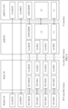
- FIG. 2 is a diagram of an example of a protocol stack architecture applicable to an embodiment of this application.
- the protocol stack architecture may include a packet data convergence protocol (packet data convergence protocol, PDCP) layer, an SRAP layer (sidelink relay adaptation protocol layer), a radio link control (radio link control, RLC) layer, a media access control (media Access control, MAC) layer, and a physical (physical, PHY) layer.
- packet data convergence protocol packet data convergence protocol
- SRAP sidelink relay adaptation protocol layer
- RLC radio link control
- media access control media Access control
- PHY physical (physical, PHY) layer.
- a service data adaptation protocol (service data adaptation protocol, SDAP) layer (not shown in FIG. 2 ) may be included above the PDCP layer.
- SDAP service data adaptation protocol
- a radio resource control (radio resource control, RRC) layer (not shown in FIG. 2 ) may be included above the PDCP layer.
- the PHY layer is located at a bottom layer
- the MAC layer, the RLC layer, and the PDCP layer are located at an intermediate layer
- the RRC layer is located at a higher layer.
- a service data adaptation protocol SDAP entity receives a data packet from an application layer, where the data packet may be a data packet from a service.
- a service is represented in different forms, and may be in a form of a flow (Quality of Service flow, QoS flow), a form of a bearer formed by mapping to a PDCP entity, or a form of a logical channel.
- QoS flow Quality of Service flow
- the SDAP entity may encapsulate the data packet, add an SDAP packet header to the data packet, and then map an obtained data packet to a packet data convergence protocol PDCP entity.
- the PDCP entity receives the data packet encapsulated by the SDAP entity, and performs header compression and decompression, encryption and decryption, integrity protection, integrity check, lower-layer service data unit SDU (Service Data Unit, SDU) duplication detection, and the like on data, to further complete transmitting the data to a radio link control RLC layer entity.
- a main function of the PDCP layer includes a security processing function.
- the security processing function may include data encryption/decryption, integrity protection/check, and the like.
- the RLC entity receives the data packet from the PDCP entity and performs data transmission.
- the RLC entity may complete segmentation and reassembly of a service data unit RLC SDU, duplication detection and protocol error detection of the RLC SDU, and the like.
- a protocol data unit PDU (Protocol Data Unit, PDU) is a data unit transmitted between peer layers.
- an RLC PDU is a data unit exchanged between an RLC layer of the transmit end and an RLC layer of the receive end.
- An SDU is a service data unit, is also referred to as a service data unit, and is a data set of a user service at a specified layer.
- the SDU is an information unit transmitted from a higher protocol layer to a lower protocol layer.
- SDUs at an Nth layer one-to-one correspond to PDUs at an upper layer.
- a transmitter adds protocol control information PCI (Protocol Control Information, PCI) to a SDU delivered by a user and encapsulates the SDU into a PDU.
- PCI Protocol Control Information
- one SDU needs to be divided into a plurality of segments, and the segments are separately encapsulated into PDUs for sending. This is SDU segmentation. Then, the receiver decapsulates the PDUs, and reassembles the PDUs into the SDU.
- a channel between the RLC layer and the media access control MAC layer is referred to as a logical channel (Logical Channel, LCH).
- LCH Logical Channel
- a logical channel type set provides different types of data transmission services for a MAC entity, and the logical channel may be identified at the PDCP layer, the RLC layer, and the MAC layer.
- the MAC entity provides a data transmission service on the logical channel, receives the data packet from the RLC entity, and implements mapping from the logical channel to a transport channel.
- the MAC entity receives service data units MAC SDUs from a plurality of logical channels, and completes multiplexing and demultiplexing of the MAC SDUs.
- a protocol data unit MAC PDU of the MAC entity is a data unit transmitted inside the MAC entity.
- the MAC entity can further complete management on priorities of different logical channels LCP (Logic Channels Priority, LCP) of a same receive end device, priority management performed between different receive end devices through dynamic scheduling, an error correction function based on a HARQ (Hybrid Automatic Repeat reQuest, HARQ) mechanism, and the like.
- LCP Logic Channels Priority
- the LCP means a process in which the MAC entity allocates resources to different logical channels based on sizes of the transmission resources and priorities of the logical channels. After an LCP process ends, zero or more resources are allocated to each logical channel. In a conventional protocol, after a resource is allocated to each logical channel, data packets are placed on the allocated resource in order.
- the physical layer provides a data service for a higher layer in a form of a transport channel.
- the physical layer performs procedures such as cyclic redundancy check (Cyclic Redundancy Check, CRC), code block segmentation, channel coding, rate matching, and code block connection, then performs operations such as scrambling, modulation, layer mapping, and precoding, and finally perform sending over an air interface.
- CRC Cyclic Redundancy Check
- radio bearers To satisfy service quality requirements of different types of services of a terminal device, one or more radio bearers (radio bearers, RBs) are introduced to a wireless network.
- the radio bearer includes a data radio bearer (data radio bearer, DRB) and a signaling radio bearer (signaling radio bearer, SRB), and is for transmitting different types of service data (including control plane signaling and user plane data) between a UE and a base station.
- DRB data radio bearer
- SRB signaling radio bearer
- UEs communicate with each other by using a sidelink radio bearer (sidelink radio bearer, SL RB), including a sidelink data radio bearer (sidelink data radio bearer, SL DRB) and a sidelink signaling radio bearer (sidelink signaling radio bearer, SL SRB).
- sidelink radio bearer sidelink radio bearer, SL RB
- sidelink data radio bearer sidelink data radio bearer, SL DRB
- sidelink signaling radio bearer sidelink signaling radio bearer
- a configuration of an RLC bearer is a configuration corresponding to an RB at a lower layer, and specifically includes configurations of resources such as the RLC entity and the logical channel.
- One RLC bearer is associated with one logical channel at the MAC layer, and one RLC bearer is associated with one PDCP entity. In other words, one RLC bearer serves one radio bearer RB.
- a communication link including a remote UE, a relay UE, and a base station is an indirect link.
- a data packet of the remote UE may be relayed and forwarded below a PDCP layer of the relay UE.
- an RLC bearer for relay on a PC5 interface is set up between the remote UE and the relay UE
- an RLC bearer for relay on a Uu interface is set up between the relay UE and the base station
- data transmission between the remote UE and the base station may be implemented.
- the relay UE maintains only the RLC bearer for relay.
- a link for direct communication between the remote UE and the base station through a Uu interface is a direct link.
- RLC layer On the direct link, between the remote UE and the base station, there is an end-to-end PDCP layer, and there are also an end-to-end RLC layer, MAC layer, and PHY layer.
- the RLC bearer for relay on the PC5 interface is referred to as a PC5 relay RLC bearer, or may be referred to as a PC5 relay RLC channel
- the RLC bearer for relay on the Uu interface is referred to as a Uu relay RLC bearer, or may be referred to as a Uu relay RLC channel
- the RLC bearer between the remote UE and the base station is referred to as a Uu RLC bearer.
- the SRAP layer (sidelink relay adaptation protocol layer) is added between the RLC layer and the PDCP layer.
- a main function of the SRAP layer (or referred to as an adaptation layer) is multiplexing and demultiplexing of radio bearers, in other words, supporting multiplexing of different radio bearers on one RLC bearer for relay and a corresponding demultiplexing process. For example, data of a plurality of radio bearers of one remote UE may be multiplexed on one PC5 relay RLC bearer.
- data of a plurality of radio bearers of different remote UEs may be multiplexed on one Uu relay RLC bearer.
- an SRAP layer of the base station may multiplex data of a plurality of radio bearers of one or more remote UEs on one Uu relay RLC bearer.
- the base station Before performing data transmission on the indirect link, the base station further performs SRAP layer configuration on the remote UE and the relay UE.
- a configuration of an SRAP layer on a remote UE side includes a mapping relationship between a radio bearer and a PC5 relay RLC bearer
- a configuration of an SRAP layer on a relay UE side includes a mapping relationship between a radio bearer and a Uu/PC5 relay RLC bearer.
- the SRAP layer of the base station receives the data packet of the remote UE from a PDCP layer, adds ID information of the remote UE and ID information of a radio bearer (for example, an SRB ID or a DRB ID) to an SRAP packet header, and then delivers an obtained data packet to the Uu relay RLC bearer.
- a radio bearer for example, an SRB ID or a DRB ID
- an adaptation layer of the relay UE may deliver the data packet to a correct PC5 relay RLC bearer based on the mapping relationship that is between the radio bearer and the PC5 relay RLC bearer and that is configured by the base station.
- the remote UE After receiving the data packet from the PC5 relay RLC bearer, the remote UE delivers, based on the ID information of the radio bearer in the SRAP packet header, the data packet to a corresponding PDCP layer for processing.
- An uplink transmission process on the indirect link is similar to this.
- the ID information such as a local ID of the remote UE may be allocated by the base station to the remote UE.
- the ID information allocated by the base station to the remote UE is unique under the base station (ID information of remote UEs connected to a same base station is different), or is unique under the relay UE (ID information of remote UEs connected to a same relay UE is different).
- the relay UE after the remote UE establishes a unicast connection to the relay UE, the relay UE sends an RRC message, for example, a SidelinkUEInformationNR (SUI) message, to the base station, to request the base station to allocate a local ID to the remote UE.
- RRC message for example, a SidelinkUEInformationNR (SUI) message
- FIG. 3 is a diagram of an example of another protocol stack architecture applicable to an embodiment of this application.
- a remote UE may communicate with a relay UE through a non-3 GPP link.
- An SRAP layer on the link between the remote UE and the relay UE or on a link between the relay UE and a base station is an optional configuration, and may be selected based on a multiplexing requirement of a radio bearer of the remote UE.
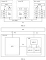
- FIG. 4 is a diagram of a network structure applicable to an embodiment of this application.
- a next generation radio access network (Next Generation Radio Access Network, NG-RAN) includes one or more gNBs connected to a 5G core (5G core) network.
- One gNB may be divided into a central unit (Central unit, CU) and a distributed unit (Distributed Unit, DU).
- Central unit CU
- DU distributed Unit
- one gNB may be divided into one gNB-CU and one or more gNB-DUs.
- One gNB-DU can be connected to only one gNB-CU.
- the CU may further include a form in which a control plane (control plane, CP) (referred to as a CU-CP in this specification) and a user plane (user plane, UP) (referred to as a CU-UP in this specification) are split.
- CP control plane
- UP user plane
- the CU may include one CU-CP and one or more CU-UPs.
- the network structure is also referred to as a CU-DU split architecture.
- the gNB-CU is responsible for RRC, SDAP, and PDCP protocol layers, and the gNB-DU is responsible for RLC, MAC, and PHY protocol layers.
- a gNB-CU-CP is responsible for the RRC and a PDCP entity corresponding to an SRB; and for the user plane, a gNB-CU-UP is responsible for the SDAP and a PDCP entity corresponding to a DRB.
- network elements may communicate with each other through interfaces shown in FIG. 4 .
- the gNB may interact with the 5GC through an NG interface
- two gNBs may interact with each other through an Xn interface
- the gNB-CU may interact with the gNB-DU through an F1 interface.
- FIG. 5 is a diagram of a user plane protocol stack architecture in a CU-DU split architecture.
- FIG. 6 is a diagram of a control plane protocol stack architecture in a CU-DU split architecture.
- protocol stack architecture has been described above. For some descriptions, refer to the foregoing descriptions. Only differences of the protocol stack architectures in the CU-DU split architecture are described herein.
- a protocol stack architecture of a base station may further include a general packet radio service tunneling protocol user plane (general packet radio service tunneling protocol user plane, GTP-U) layer, a user datagram protocol (user datagram protocol, UDP) layer, a network interconnection protocol (internet protocol, IP) layer, an L2 (layer 2) layer, and an L1 (layer 1) layer.
- the L2 layer is a link layer.
- the L2 layer may be a data link layer in an open communication system interconnection (open system interconnection, OSI) reference model.
- the L1 layer may be a physical layer.
- the L1 layer may be a physical layer in the OSI reference model.
- a gNB-CU is responsible for an RRC layer, an SDAP layer, and a PDCP layer, and a gNB-DU is responsible for an RLC layer, a MAC layer, and a PHY layer.
- a gNB-CU-CP is responsible for the RRC and a PDCP entity corresponding to an SRB; and for a user plane, a gNB-CU-UP is responsible for the SDAP layer and a PDCP entity corresponding to a DRB.
- an SRAP layer is located on a DU side, and the gNB-CU determines configuration information of the SRAP layer; the gNB-DU determines a configuration of a PC5/Uu relay RLC bearer based on an indication of the gNB-CU; and the gNB-CU allocates a local ID of a remote UE, sends an F1AP message to the remote UE to perform SRAP layer configuration and PC5 RLC bearer configuration on the remote UE, and sends an F1AP message to a relay UE to perform SRAP layer configuration and PC5/Uu RLC bearer configuration on the relay UE.
- an end-to-end SRAP layer, RLC layer, MAC layer, and PHY layer between the remote UE and the relay UE may also be respectively referred to as a PC5-SRAP layer, a PC5-RLC layer, a PC5-MAC layer, and a PC5-PHY layer.
- an end-to-end SRAP layer, RLC layer, MAC layer, and PHY layer between the relay UE and the base station may also be respectively referred to as a Uu-SRAP layer, a Uu-RLC layer, a Uu-MAC layer, and a Uu-PHY layer.
- FIG. 7 is a diagram of communication between a remote terminal device and a base station in a CU-DU split architecture.
- the base station includes two parts: a CU and a DU.
- the CU may be connected to the DU through an F1 interface, and one CU may be connected to one or more DUs.
- a plurality of communication links may be established between a remote UE 710 and the base station.
- the remote UE 710 may be connected to the base station through both a direct link and an indirect link.
- the remote UE 710 may be connected to a gNB-DU via a relay UE 720, and the remote UE 710 may alternatively be directly connected to the gNB-DU.
- the remote UE and the relay UE 720 may be connected to a same gNB-DU connected to a same gNB-CU. This scenario is referred to as an intra-gNB-DU scenario.
- the remote UE 710 may be directly connected to a gNB-DU 1, and the remote UE 710 may alternatively be connected to a gNB-DU 2 via a relay UE 720.
- the gNB-DU 1 and the gNB-DU 2 share a same gNB-CU.
- the remote UE 710 and the relay UE 720 may be connected to different gNB-DUs connected to a same gNB-CU. This scenario is referred to as an inter-gNB-DU scenario.
- a direct link and an indirect link exist between the gNB-DU and the remote terminal device.
- the gNB-CU may explicitly indicate the gNB-DU to set up a PC5 relay RLC bearer corresponding to the radio bearer on the indirect link, but the gNB-DU cannot determine whether a configuration of a Uu RLC bearer corresponding to the radio bearer on the direct link needs to be provided.
- a direct link exists between the gNB-DU 1 and the remote UE, and an indirect link exists between the gNB-DU 2 and the remote UE.
- Both the gNB-DU 1 and the gNB-DU 2 need to send configurations related to a radio bearer to the gNB-CU.
- the gNB-DU 1 and the gNB-DU 2 include the configurations related to the radio bearer in same information elements.
- the gNB-CU may fail to identify and combine the two same information elements, and consequently, send only one of the information elements to the remote UE. This is not conducive for the remote UE to configure the radio bearer on the two links.
- the following uses a case in which a base station establishes an indirect link to a remote UE when a direct link exists between the base station and the remote UE as an example for description.
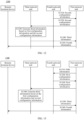
- FIG. 8 shows a communication method according to an embodiment of this application. The method is applied to an intra-gNB-DU scenario, and the method includes the following steps.
- a remote UE sends a measurement report (measurement report) to a gNB-CU, and correspondingly, the gNB-CU receives the measurement report sent by the remote UE.
- the remote UE sends the measurement report to the gNB-CU via the gNB-DU, to request the gNB-CU to establish a new indirect link between the remote UE and the gNB-DU.
- the measurement report may include information about one or more candidate relay UEs and/or information about one or more candidate cells.
- the information about the candidate relay UE may include one or more of the following: an L2 ID of the candidate relay UE, information about a serving cell of the relay UE, for example, an NR cell identity (NR cell identity, NCI) or an NR cell global identity (NR cell global identity, NCGI), and reference signal received power (reference signal received power, RSRP) of a sidelink between the remote UE and the candidate relay UE.
- the information about the serving cell may include one or more of the following: a cell identifier such as the NCI or the NCGI, and Uu interface signal quality measured by the remote UE in the candidate cell.
- the gNB-CU may trigger multi-path (multi-path) configuration.
- the base station when a link connection exists between a base station and the remote UE, the base station establishes a new link connection to the remote UE. For example, when an indirect link exists between the base station and the remote UE, the base station establishes a direct link to the remote UE. Alternatively, when a direct link exists between the base station and the remote UE, the base station establishes an indirect link to the remote UE. Alternatively, the base station directly establishes a plurality of communication links between the base station and the remote UE.
- S802 The gNB-CU selects a target relay UE.
- the gNB-CU may alternatively actively select a target relay UE for the remote UE based on information such as network quality of the remote UE on the direct link and a data transmission rate on a radio bearer, and may further configure the target relay UE and the remote UE, to establish an indirect link between the remote UE, the target relay UE, and the base station.
- the gNB-CU sends a first context modification request (context modification request (relay UE)) message to the gNB-DU, and correspondingly, the gNB-DU receives the first context modification request message sent by the gNB-CU.
- a first context modification request context modification request (relay UE)) message
- the gNB-DU receives the first context modification request message sent by the gNB-CU.
- the first context modification request message is a context modification request message corresponding to the target relay UE.
- the first context modification request message is associated with the target relay UE.
- the context modification request message may carry F1AP ID information of the target relay UE, to distinguish from a context modification request message of another UE.
- the gNB-CU may perform relay configuration on the target relay UE.
- the gNB-CU may determine a configuration of an SRAP layer on the target relay UE side.
- the configuration of the SRAP layer may include, for example, a mapping relationship between at least one radio bearer (SRB or DRB) of the remote UE and a Uu/PC5 relay RLC bearer.
- mapping relationship between the at least one radio bearer of the remote UE and the Uu/PC5 relay RLC bearer may be a mapping relationship between an ID of the at least one radio bearer (an SRB ID or a DRB ID) of the remote UE and an ID of the Uu/PC5 relay RLC bearer.
- the gNB-DU may generate the configuration of the PC5 relay RLC bearer and the configuration of the Uu relay RLC bearer of the target relay UE based on the first context modification request message of the target relay UE, and send the generated configurations to the gNB-CU by using the first context modification response message.
- the configuration of the PC5 relay RLC bearer and the configuration of the Uu relay RLC bearer may include one or more of the following information: an ID of the Uu relay RLC bearer, an ID of the PC5 relay RLC bearer, a configuration of a Uu-RLC entity, a configuration of a PC5-RLC entity, a logical channel identity (logical channel identity, LCID) corresponding to the Uu relay RLC bearer, a logical channel identity corresponding to the PC5 relay RLC bearer, a configuration of a logical channel corresponding to the Uu relay RLC bearer or the PC5 relay RLC bearer, and the like.
- an ID of the Uu relay RLC bearer an ID of the PC5 relay RLC bearer
- a configuration of a Uu-RLC entity a configuration of a PC5-RLC entity
- a logical channel identity logical channel identity, LCID
- the configuration of the Uu-RLC entity or the PC5-RLC entity may include an RLC mode and a corresponding parameter.
- the RLC mode may include an acknowledged mode (acknowledged mode, AM), an unacknowledged mode (unacknowledged mode, UM), and the like.
- the corresponding parameter may include a length of a sequence number (sequence number, SN) field, a timer (timer) for retransmission poll, a maximum quantity of retransmissions, and the like.
- Configuration information of the logical channel may include a logical channel priority, a prioritized bit rate, and the like.
- the gNB-CU sends a downlink RRC message to the gNB-DU (DL RRC message transfer).
- the downlink RRC message may carry an RRC reconfiguration (RRCReconfiguration) message sent to the target relay UE.
- the RRC reconfiguration message may include configuration information of the PC5 relay RLC bearer and the Uu relay RLC bearer of the target relay UE, to indicate the target relay UE to configure the PC5 relay RLC bearer and the Uu relay RLC bearer based on the configuration information.
- the gNB-DU sends the RRC reconfiguration message to the target relay UE.
- the RRC reconfiguration message may alternatively be an RRC setup (RRCsetup) message.
- the target relay UE sends an RRC reconfiguration complete (RRCReconfigurationComplete) message to the gNB-DU, to indicate that reconfiguration is completed.
- RRC reconfiguration complete RRCReconfigurationComplete
- the gNB-DU sends an uplink RRC message to the gNB-CU (UL RRC message transfer).
- the uplink RRC message may carry the RRC reconfiguration complete message.
- the gNB-DU may forward the RRC reconfiguration complete message.
- the target relay UE may set up the PC5 relay RLC bearer and the Uu relay RLC bearer based on the configuration information of the PC5 relay RLC bearer and the Uu relay RLC bearer. This includes setting up an RLC entity, reconfiguring or setting up a logical channel, or the like.
- the target relay UE may send the RRC reconfiguration complete message to the gNB-CU by using S807 and S808, to indicate that the PC5 relay RLC bearer and the Uu relay RLC bearer on the target relay UE side have been set up. Therefore, based on the foregoing configuration, the target relay UE may provide a relay service for the remote UE on the indirect link.
- steps S809 and S810 are for generating required multi-path configuration information for the remote UE.
- the gNB-CU sends a second context modification request (context modification request (remote UE)) message to the gNB-DU, and correspondingly, the gNB-DU receives the second context modification request message sent by the gNB-CU.
- a second context modification request context modification request (remote UE)
- the second context modification request message is a context modification request message corresponding to the remote UE, and is for modifying a context of the remote UE.
- the second context modification request message is associated with the remote UE.
- the second context modification request message may carry F1AP ID information of the remote UE, to distinguish from a context modification request message of another UE.
- the gNB-CU may determine configuration information required by the remote UE to establish the indirect link, for example, a configuration of an SRAP layer on the remote UE side.
- the configuration of the SRAP layer may include the mapping relationship between the radio bearer (SRB or DRB) of the remote UE and the PC5 relay RLC bearer.
- the second context modification request message may include the configuration of the SRAP layer on the remote UE side.
- the configuration of the SRAP layer has been described in S803. For details, refer to the related descriptions of S803. Details are not described herein again.
- the second context modification request message may further include an ID of the PC5 relay RLC bearer and QoS information that the PC5 relay RLC bearer needs to meet, to indicate the gNB-DU to provide a configuration of the PC5 relay RLC bearer.
- the gNB-DU may determine the configuration of the PC5 relay RLC bearer based on the QoS information. In other words, on the indirect link, the gNB-DU may determine, based on an indication of the gNB-CU, whether the configuration of the PC5 relay RLC bearer corresponding to the radio bearer needs to be provided.
- PC5 relay RLC bearers may be set up between the remote UE and the target relay UE, and each PC5 relay RLC bearer may correspond to at least one radio bearer.
- the remote UE may be connected to a plurality of target relay UEs, and PC5 relay RLC bearers between the remote UE and different target relay UEs may use a same ID of a PC5 relay RLC bearer.
- ID information of the target relay UE for example, an L2 ID of the target relay UE
- ID information of a serving cell of the target relay UE for example, an L2 ID of the target relay UE
- index (index) allocated by the gNB-CU to the target relay UE connected to the remote UE may be used.
- the ID of the PC5 relay RLC bearer is x
- an ID of a first target relay UE is y
- an ID of a second target relay UE is z
- xy or y may be used as identification information of a PC5 relay RLC bearer between the remote UE and the first target relay UE
- xz or z may be used as identification information of a PC5 relay RLC bearer between the remote UE and the second target relay UE.
- the second context modification request message may further include first indication information, and the first indication information may indicate the gNB-DU to newly set up or modify the radio bearer of the remote UE.
- the first context modification request message may carry a radio bearer setup list or a radio bearer modification list, for example, an SRB to Be Setup List/DRB to Be Setup List or SRB to Be Modified List/DRB to Be Modified List information element (information element, IE), to indicate the gNB-DU to newly set up or modify the radio bearer of the remote UE.
- the radio bearer setup list or the radio bearer modification list may further carry QoS information that each radio bearer needs to meet.
- configuration types of the radio bearer may include the following:
- the gNB-CU may determine the configuration type of the radio bearer based on a quality of service requirement of the radio bearer. For example, if the radio bearer 1 requires a low delay, the gNB-CU may configure the radio bearer 1 as the third configuration type; or if communication quality of the direct link is better, the gNB-CU may configure the radio bearer 1 as the first configuration type.
- the third configuration type may include that the radio bearer is configured to perform PDCP duplication or configured to perform PDCP split.
- the PDCP duplication may also be referred to as packet duplication, to be specific, a data packet is repeatedly sent once.
- a data packet may be transmitted to an RLC entity, the data packet is duplicated once, and a data packet obtained through duplication is transmitted to another RLC entity.
- the radio bearer is configured to perform PDCP duplication, the data packet is transmitted to the PC5 relay RLC bearer, and the data packet obtained through duplication is transmitted to a Uu RLC bearer.
- each data packet is randomly transmitted to the PC5 relay RLC bearer or a Uu RLC bearer.
- the gNB-DU when receiving the indication information indicating to newly set up or modify the radio bearer of the remote UE, the gNB-DU does not determine a link on which an RLC bearer needs to be configured for the radio bearer that is indicated by the gNB-CU to set up or modify. If the radio bearer is configured on the indirect link (corresponding to the second configuration type and the third configuration type), the gNB-CU may include, in the second context modification request message, the ID of the PC5 relay RLC bearer and the QoS information that the PC5 relay RLC bearer needs to meet, to indicate the gNB-DU to determine the configuration of the PC5 relay RLC bearer. However, when the radio bearer is configured on the direct link (corresponding to the first configuration type and the third configuration type), the gNB-DU does not determine whether a configuration of the Uu RLC bearer corresponding to the radio bearer needs to be provided.
- the first indication information may include the configuration type of the radio bearer of the remote UE, and the gNB-DU may determine, based on the configuration type of the radio bearer, whether the corresponding configuration of the Uu RLC bearer on the direct link needs to be provided for the radio bearer.
- the first indication information may indicate the configuration type of the radio bearer by using 2-bit indication information or Boolean indication information. For example, 0 indicates the first configuration type, 1 indicates the second configuration type, and 2 indicates the third configuration type. For another example, 0 indicates the first configuration type, 1 indicates the second configuration type, 2 indicates the PDCP duplication, and 3 indicates the PDCP split.
- the gNB-DU when the radio bearer 1 of the remote UE is configured as the first configuration type, the gNB-DU needs to provide a configuration of a Uu RLC bearer corresponding to the radio bearer 1, namely, a configuration of an RLC bearer on the direct link; when the radio bearer 1 is configured as the second configuration type, the gNB-DU needs to provide a configuration of a PC5 relay RLC bearer corresponding to the radio bearer 1, namely, a configuration of an RLC bearer on the indirect link; or when the radio bearer 1 is configured as the second configuration type, the gNB-DU needs to provide a configuration of a PC5 relay RLC bearer and a configuration of a Uu RLC bearer.
- the gNB-DU needs to provide the configuration of the Uu RLC bearer on the direct link.
- the first indication information may indicate whether the gNB-DU needs to provide the configuration of the Uu RLC bearer corresponding to the radio bearer.
- the first indication information may be Boolean indication information, where true indicates that the gNB-DU needs to determine and provide the configuration of the Uu RLC bearer corresponding to the radio bearer, and false indicates that the Uu RLC bearer corresponding to the radio bearer does not need to be provided.
- the first indication information may further indicate a quantity of Uu RLC bearers, to indicate the gNB-DU to provide a plurality of corresponding configurations of the Uu RLC bearers, each configuration of the Uu RLC bearer corresponds to one link between the remote terminal and the gNB-DU.
- the first indication information may explicitly indicate the gNB-DU to determine the configuration of the Uu RLC bearer corresponding to the radio bearer. Specifically, the first indication information may indicate that a link identifier of the Uu RLC bearer needs to be provided, and the link identifier is determined by the gNB-CU. Similarly, in the scenario in which the remote terminal is connected to the gNB-DU through the plurality of direct links, the gNB-CU may indicate identifiers of the plurality of direct links.
- the first indication information may explicitly indicate that the gNB-DU does not provide the configuration of the Uu RLC bearer corresponding to the radio bearer.
- the gNB-DU may determine the configuration of the Uu RLC bearer based on the QoS information corresponding to the radio bearer.
- the second context modification request message may further include multi-path indication information, and the multi-path indication information indicates that the radio bearer of the remote UE is configured in a switching scenario or a multi-path scenario.
- the multi-path indication information may also be referred to as path addition indication information.
- the multi-path indication information may perform indication in the following manners. For example, if the first context modification request message does not include the multi-path indication information (for example, the multi-path indication information is 0, or is indicated by using a specific IE name), the radio bearer of the remote UE is configured in the switching scenario.
- the switching scenario may include switching from a direct link to an indirect link or switching from the indirect link to the direct link. Different identifiers may be further used for the multi-path indication information to distinguish between the two types of switching.
- the radio bearer of the remote UE is configured in the multi-path scenario, so that the gNB-DU can provide, for the remote UE or the target relay UE, a configuration corresponding to the multi-path scenario.
- the second context modification request message may further include the ID information of the target relay UE, to indicate a target relay UE to which the remote UE establishes a communication connection, for example, establishes a unicast connection.
- the gNB-DU sends a second context modification response (context modification response (remote UE)) message to the gNB-CU, and correspondingly, the gNB-CU receives the second context modification response message sent by the gNB-DU.
- a second context modification response context modification response (remote UE)
- the second context modification response message may include the configuration of the PC5 relay RLC bearer and/or the configuration of the Uu RLC bearer that correspond/corresponds to the radio bearer of the remote UE.
- the configuration of the Uu RLC bearer may include one or more of the following information: an ID of the Uu RLC bearer, a configuration of a Uu-RLC entity, a logical channel identity (logical channel identity, LCID) corresponding to the Uu RLC bearer, a configuration of a logical channel corresponding to the Uu RLC bearer, and the like.
- an ID of the Uu RLC bearer a configuration of a Uu-RLC entity
- a logical channel identity (logical channel identity, LCID) corresponding to the Uu RLC bearer a configuration of a logical channel corresponding to the Uu RLC bearer, and the like.
- the downlink RRC message may carry an RRC reconfiguration (RRCReconfiguration) message sent to the remote UE.
- RRCReconfiguration RRC reconfiguration
- the RRC reconfiguration message may alternatively be an RRC setup (RRCsetup) message.
- S813 Set up the PC5 relay RLC bearer and/or the Uu RLC bearer.
- the remote UE may set up the PC5 relay RLC bearer and/or the Uu RLC bearer based on the configuration information of the PC5 relay RLC bearer and/or the Uu RLC bearer. This includes setting up an RLC entity, reconfiguring or setting up a logical channel, or the like.
- the gNB-DU sends an uplink RRC message to the gNB-CU (UL RRC message transfer).
- the uplink RRC message may carry the RRC reconfiguration complete message.
- the gNB-DU may forward the RRC reconfiguration complete message.
- the remote UE may send the RRC reconfiguration complete message to the gNB-CU by using S814 and S815, to indicate that the PC5 relay RLC bearer and/or the Uu RLC bearer on the remote UE side have been set up.
- FIG. 9 shows a communication method according to an embodiment of this application. The method is applied to an intra-gNB-DU scenario, and the method includes the following steps.
- a remote UE sends a measurement report to a gNB-CU, and correspondingly, the gNB-CU receives the measurement report sent by the remote UE.
- an indirect link already exists between the remote UE and a gNB-DU and the remote UE may communicate with the gNB-DU via a relay UE.
- the remote UE sends the measurement report to the gNB-CU via the relay UE and the gNB-DU, to request the gNB-CU to establish a new direct link between the remote UE and the gNB-DU.
- the gNB-CU determines to newly add the direct link between the gNB-DU and the remote UE.
- the gNB-CU may determine, based on radio signal strength between the remote UE and the currently connected relay UE or between the remote UE and one or more candidate cells, whether to newly add the direct link for the remote UE. For example, if the radio signal strength between the remote UE and the currently connected relay UE is weak, the gNB-CU may determine to newly add the direct link between the gNB-DU and the remote UE.
- S901 is an optional step.
- the gNB-CU may actively newly add the direct link for the remote UE.
- the gNB-CU sends a first context modification request message to the gNB-DU, and correspondingly, the gNB-DU receives the first context modification request message sent by the gNB-CU.
- the gNB-DU sends a first context modification response message to the gNB-CU, and correspondingly, the gNB-CU receives the first context modification response message sent by the gNB-DU.
- the gNB-DU sends an RRC reconfiguration message to the relay UE.
- the relay UE sends an RRC reconfiguration complete (RRCReconfigurationComplete) message to the gNB-DU.
- the gNB-DU sends an uplink RRC message to the gNB-CU (UL RRC message transfer).
- steps S903 to S908 are a reconfiguration procedure on a relay UE side, including indicating the gNB-DU to determine a configuration of a PC5/Uu relay RLC bearer.
- steps S903 to S908 refer to the related descriptions of steps S803 to S808. Details are not described herein again.
- the gNB-CU sends a second context modification request message to the gNB-DU, and correspondingly, the gNB-DU receives the second context modification request message sent by the gNB-CU.
- the gNB-DU sends a second context modification response message to the gNB-CU, and correspondingly, the gNB-CU receives the second context modification response message sent by the gNB-DU.
- the first radio bearer may correspond to one or more second RLC bearers.
- the configuration information includes the configuration of the first RLC bearer.
- the configuration information includes the configuration of the second RLC bearer.
- the configuration information includes the configuration of the first RLC bearer and the configuration of the second RLC bearer.
- the configuration information may further include configurations of RLC bearers corresponding to a plurality of radio bearers.
- the configuration information may include the configuration of the first RLC bearer corresponding to the first radio bearer, a configuration of a second RLC bearer corresponding to the second radio bearer, and a configuration of a first RLC bearer and a configuration of a second RLC bearer that correspond to the third radio bearer.
- the remote terminal device receives the configuration of the SRAP layer from the first network unit, where the configuration of the SRAP layer includes the mapping relationship between the first radio bearer and the second RLC bearer.
- the remote terminal device may configure the SRAP layer based on the configuration of the SRAP layer.
- the following uses an example in which a direct link exists between a remote UE and a gNB-DU 1 and an indirect link between the remote UE and a gNB-DU 2 is newly set up in an inter-gNB-DU scenario for description.
- FIG. 11 shows a communication method according to an embodiment of this application. The method is applied to an inter-gNB-DU scenario, and the method includes the following steps.
- a remote UE sends a measurement report to a gNB-CU, and correspondingly, the gNB-CU receives the measurement report sent by the remote UE.
- a direct link already exists between the remote UE and a gNB-DU 1, and the remote UE may directly communicate with the gNB-DU 1 through a Uu interface.
- a relay UE may also communicate with a gNB-DU 2 through a Uu interface.
- the remote UE sends the measurement report to the gNB-CU via the gNB-DU 1, to request the gNB-CU to establish a new indirect link for the remote UE.
- the gNB-DU 1 and the gNB-DU 2 are different DUs connected to a same gNB-CU.
- one or more candidate relay UEs each may communicate with the DU connected to the gNB-CU through a Uu interface.
- the one or more candidate relay UEs may be communicatively connected to a base station through a direct link.
- the measurement report may include information about the one or more candidate relay UEs and/or information about one or more candidate cells.
- the information about the candidate relay UE may include one or more of the following: an L2 ID of the candidate relay UE, information about a serving cell of the relay UE, for example, an NR cell identity (NR cell identity, NCI) or an NR cell global identity (NR cell global identity, NCGI), and reference signal received power (reference signal received power, RSRP) of a sidelink between the remote UE and the candidate relay UE.
- the information about the candidate cell may include one or more of the following: a cell identifier such as the NCI or the NCGI, and Uu interface signal quality measured by the remote UE in the candidate cell.
- S1102 The gNB-CU determines to newly add an indirect communication link for the remote UE.
- the gNB-CU may determine to newly add the indirect communication link for the remote UE, and then select an appropriate target relay UE for the remote UE from the one or more candidate relay UEs, to newly establish the indirect link for the remote UE.
- select an appropriate target relay UE for the remote UE refer to the related descriptions of step S802. Details are not described herein again.
- the determined target relay UE and the remote UE are connected to different gNB-DUs.
- the remote UE is connected to the gNB-DU 1
- the target relay UE is connected to the gNB-DU 2.
- the gNB-CU may determine a configuration type of a radio bearer of the remote UE. For example, all radio bearers of the remote UE are originally configured on the direct link, and the gNB-CU may determine which radio bearers need to be configured on the indirect link, or the gNB-CU may determine which radio bearers need to be configured to perform PDCP duplication or PDCP split.
- the gNB-CU sends a first context modification request message to the gNB-DU 2, and correspondingly, the gNB-DU 2 receives the first context modification request message sent by the gNB-CU.
- the first context modification request message is associated with the target relay UE, and the first context modification request message is used by the gNB-CU to indicate the gNB-DU 2 to generate a configuration required by a target relay UE side.
- S1104 The gNB-DU 2 sends a first context modification response message to the gNB-CU, and correspondingly, the gNB-CU receives the first context modification response message sent by the gNB-DU 2.
- S1105 The gNB-CU sends a downlink RRC message to the gNB-DU 2.
- the gNB-DU 2 sends an RRC reconfiguration message to the relay UE.
- the relay UE sends an RRC reconfiguration complete message to the gNB-DU.
- steps S1103 to S1108 are also a reconfiguration procedure on the relay UE side.
- the gNB-DU 2 may generate a configuration of a PC5/Uu relay RLC bearer on the relay UE side based on the first context modification request message of the relay UE.
- steps S1103 to S1108 refer to the related descriptions of steps S803 to S808.
- S1109 The gNB-CU sends a third context modification request message to the gNB-DU 2, and correspondingly, the gNB-DU 2 receives the third context modification request message sent by the gNB-CU. If a context setup procedure between the remote terminal and the gNB-CU and the gNB-DU 2 is not completed before S1109, the gNB-CU may alternatively send a third context setup request message to the gNB-DU 2 in the procedure. The following uses the third context modification request message as an example for description.
- the third context modification request message is a context modification request message corresponding to the remote UE.
- the third context modification request message is associated with the remote UE.
- the context modification request message may carry F1AP ID information of the remote UE, to distinguish from a context modification request message of another UE.
- the gNB-CU may further indicate, by using the third context modification request message, to newly set up or modify the radio bearer.
- the third context modification request message may include a radio bearer setup list or a radio bearer modification list, for example, an SRB to Be Setup List/DRB to Be Setup List or SRB to Be Modified List/DRB to Be Modified List IE, to indicate the gNB-DU 2 to set up or modify the radio bearer of the remote UE on the indirect link.
- a radio bearer in the radio bearer setup list or the radio bearer modification list is a radio bearer of a second configuration type or a radio bearer of a third configuration type, namely, a radio bearer that needs to be configured on the indirect link.
- the gNB-DU 2 may determine the configuration of the PC5 relay RLC bearer based on the ID of the PC5 relay RLC bearer and the QoS information corresponding to the PC5 relay RLC bearer that are indicated by the gNB-CU.
- the gNB-DU 2 may generate a CellGroupConfig IE including the configuration of the PC5 relay RLC bearer, and then send the CellGroupConfig IE to the gNB-CU by using the third context modification response message.
- S1111 The gNB-CU sends a fourth context modification request message to the gNB-DU 1, and correspondingly, the gNB-DU 1 receives the fourth context modification request message sent by the gNB-CU.
- the fourth context modification request message is a context modification request message corresponding to the remote UE.
- the fourth context modification request message is associated with the remote UE.
- the context modification request message may carry the F1AP ID information of the remote UE, to distinguish from the context modification request message of the another UE.
- the gNB-CU may configure the remote UE on the direct link by interacting with the gNB-DU 1.
- the fourth context modification request message may include a radio bearer setup list or a radio bearer modification list, for example, an SRB to Be Setup List/DRB to Be Setup List or SRB to Be Modified List/DRB to Be Modified List IE, to indicate the gNB-DU 1 to set up or modify the radio bearer of the remote UE on the direct link.
- a radio bearer setup list for example, an SRB to Be Setup List/DRB to Be Setup List or SRB to Be Modified List/DRB to Be Modified List IE, to indicate the gNB-DU 1 to set up or modify the radio bearer of the remote UE on the direct link.
- a radio bearer in the radio bearer setup list or the radio bearer modification list is a radio bearer of a first configuration type or a radio bearer of the third configuration type, namely, a radio bearer that needs to be configured on the direct link.
- the third context modification request message may further include the multi-path indication information, to indicate the gNB-DU 2 to perform multi-path configuration or switching configuration for the remote UE.
- the gNB-DU 1 sends a fourth context modification response message to the gNB-CU, and correspondingly, the gNB-CU receives the fourth context modification response message sent by the gNB-DU 1.
- the gNB-DU 1 may determine, based on the radio bearer setup list or the radio bearer modification list, a configuration of a Uu RLC bearer corresponding to each radio bearer in the list.
- the gNB-DU 2 may generate a CellGroupConfig IE including the configuration of the Uu RLC bearer, and then send the CellGroupConfig IE to the gNB-CU by using the fourth context modification response message.
- the CellGroupConfig IE generated by the gNB-DU 1 may include a configuration of a Uu RLC bearer corresponding to one or more radio bearers of the first configuration type or the third configuration type.
- the gNB-CU may receive CellGroupConfig IEs sent by two different DUs.
- the gNB-CU cannot parse the two CellGroupConfig IEs, and consequently, cannot combine the two CellGroupConfig IEs into one CellGroupConfig IE or send the CellGroupConfig IE to the remote UE.
- the gNB-CU may send only one of the CellGroupConfig IEs to the remote UE. In other words, the remote UE may fail to receive complete configurations of RLC bearers on two links.
- the gNB-CU may indicate the gNB-DU 1 and the gNB-DU 2 to include configurations of RLC bearers on different links in different information elements.
- the gNB-CU may indicate the gNB-DU 1 to include the configuration of the Uu RLC bearer in a first information element, and indicate the gNB-DU 2 to include the configuration of the PC5 relay RLC bearer in a second information element.
- the gNB-CU may indicate that a primary link of the remote UE is on a gNB-DU 1 side, and a secondary link of the remote UE is on a gNB-DU 2 side.
- a DU on the primary link needs to include a configuration of an RLC bearer on the primary link in a CellGroupConfig-firstPath IE.
- the gNB-DU1 includes the configuration of the Uu RLC bearer in the CellGroupConfig-firstPath IE.
- a DU on the secondary link needs to include a configuration of an RLC bearer on the secondary link in a CellGroupConfig-SecondaryPath IE.
- the gNB-DU 2 includes the configuration of the PC5 relay RLC bearer in the CellGroupConfig-SecondaryPath IE.
- the gNB-CU may parse the two information elements to obtain the configurations of the RLC bearers on the two links, and send the configurations to the remote UE by using an RRC message.
- An embodiment of this application further provides a communication method.
- a first network unit (corresponding to a gNB-CU) may receive configuration information of a radio bearer on two links from a third network unit (corresponding to a gNB-DU 1) or a fourth network unit (corresponding to a gNB-DU 2), to provide complete configuration information for a remote UE.
- FIG. 12 shows a communication method according to an embodiment of this application. The method includes the following steps.
- a third network unit sends first configuration information to a first network unit, and correspondingly, the first network unit receives the first configuration information from the third network unit.
- the first network unit sends the first configuration information to a fourth network unit, and correspondingly, the fourth network unit receives the first configuration information.
- a remote terminal device may communicate with a second network unit through a third link and a fourth link.
- the third link is a link between the remote terminal device and the third network unit
- the fourth link is a link through which the fourth network unit is connected to the remote terminal device via a relay terminal device.
- the first network unit may be the gNB-CU in the embodiment shown in FIG. 11
- the third network unit may be the gNB-DU 1
- the fourth network unit may be the gNB-DU 2.
- the third link may be a direct link
- the fourth link may be an indirect link.
- the remote terminal device may communicate with the third network unit through a Uu interface.
- the remote terminal device may communicate with the second network unit via the relay terminal device.
- the first configuration information may be the CellGroupConfig IE generated by the gNB-DU 1 in the embodiment shown in FIG. 11 .
- the first configuration information may include configurations of one or more Uu RLC bearers generated by the third network unit.
- the Uu RLC bearer may also be referred to as a third RLC bearer.
- steps S1210 and S1220 are a process in which the third network unit sends the first configuration information to the fourth network unit via the first network unit, and the first network unit performs a forwarding function in the process.
- the fourth network unit may send second configuration information to the third network unit via the first network unit.
- the second configuration information may be the CellGroupConfig IE generated by the gNB-DU 2 in the embodiment shown in FIG. 11 .
- the second configuration information may include configurations of one or more PCS relay RLC bearers generated by the fourth network unit.
- the PCS relay RLC bearer may be referred to as a fourth RLC bearer.
- the first network unit may choose to send, to the fourth network unit, the first configuration information generated by the third network unit, or the first network unit may choose to send the second configuration information of the fourth network unit to the third network unit.
- the first network unit receives configuration information of a network unit on a side of a previously established link, and then sends the configuration information to a network unit on a side of a later added link.
- the direct link already exists between the third network unit and the remote terminal, and the indirect link between the fourth network unit and the remote terminal device is added later.
- the first network unit may receive the first configuration information of the third network unit, and send the first configuration information to the fourth network unit.
- the first network unit may randomly select one of the third network unit and the fourth network unit, and then send the configuration information corresponding to the one of the third network unit and the fourth network unit to the other network unit.
- the first network unit always sends first received configuration information to the other network unit.
- the first network unit first receives the first configuration information sent by the third network unit, and sends the first configuration information to the fourth network unit.
- the first network unit always sends, to the other network unit, the configuration information generated by one of the third network unit and the fourth network unit, and the other network unit generates third information including the two types of configuration information.
- the fourth network unit generates the third information based on the first configuration information and the second configuration information.
- the fourth network unit may generate, based on the first configuration information generated by the third network unit and the second configuration information generated by the fourth network unit, the third information including the first configuration information and the second configuration information.
- the gNB-DU 2 may generate a new CellGroupConfig IE based on the CellGroupConfig IE generated by the gNB-DU 1 and the CellGroupConfig IE generated by the gNB-DU 2.
- the new CellGroupConfig IE may include configurations carried in the CellGroupConfig IEs generated by the two different DUs.
- the third network unit generates the third information based on the first configuration information and the second configuration information.
- the fourth network unit sends the third information to the first network unit, and correspondingly, the first network unit receives the third information from the fourth network unit.
- the third network unit sends the third information to the first network unit, and correspondingly, the first network unit receives the third information from the third network unit.
- the first network unit sends fourth information to the remote terminal device, and correspondingly, the remote terminal device receives the fourth information from the first network unit.
- the fourth information may include the first configuration information and the second configuration information.
- the remote terminal device may receive complete configurations of the RLC bearers on the two links.
- the fourth information may be an RRC reconfiguration message or an RRC setup message sent by the first network unit to the remote terminal device.
- the fourth information may further include an ID of a target relay UE, to indicate the remote UE to establish a connection to the target relay UE.
- the fourth information may further include a configuration of an SRAP layer, and the configuration of the SRAP layer includes a mapping relationship between each radio bearer of the remote terminal device and one or more fourth RLC bearers.
- FIG. 13 shows a communication method according to an embodiment of this application. The method includes the following steps.
- a first network unit sends fifth information to a fourth network unit, and correspondingly, the fourth network unit receives the fifth information from the first network unit.
- the first network unit sends the fifth information to the third network unit, and correspondingly, the third network unit receives the fifth information from the first network unit.
- the fifth information may indicate that the third network unit or the fourth network unit is a primary network unit, or the fifth information may indicate that a link on a third network unit side or a link on a fourth network unit side is a primary link, and a network unit on the primary link is the primary network unit.
- a network unit other than the primary network unit in the third network unit and the fourth network unit is a secondary network unit, or a link other than the primary link in the two links is a secondary link.
- the fifth information may indicate that the third network unit or the fourth network unit is a secondary network unit, or the fifth information may indicate that a link on a third network unit side or a link on a fourth network unit side is a secondary link, and a network unit on the secondary link is the secondary network unit.
- the first network unit always sends, to the primary network unit, configuration information generated by the secondary network unit, and the primary network unit generates third information and sends the third information to the first network unit.
- the first network unit always sends, to the secondary network unit, configuration information generated by the primary network unit, and the secondary network unit generates third information and sends the third information to the first network unit.
- the first network unit always sends, to a network unit on a secondary link side, configuration information generated by a network unit on a primary link side, and the network unit on the secondary link side generates third information and sends the third information to the first network unit.
- the first network unit always sends, to a network unit on a primary link side, configuration information generated by a network unit on a secondary link side, and the network unit on the primary link side generates third information and sends the third information to the first network unit.
- the first network unit may specify a network unit that generates the third information including first configuration information and second configuration information, and obtain the third information, to provide complete configuration information of a radio bearer for a remote terminal device.
- the first network unit sends sixth information to the fourth network unit and/or the third network unit, to indicate the fourth network unit and the third network unit to perform multi-path configuration or switching configuration for the remote terminal device.
- the sixth information may be the multi-path indication information in the embodiment shown in FIG. 8 or FIG. 11 .
- step S809 Details are not described herein again.
- the following uses an example in which the fifth information indicates that the third network unit is the primary network unit for description.
- the fourth network unit sends the second configuration information to the first network unit, and correspondingly, the first network unit receives the second configuration information from the fourth network unit.
- the first network unit sends the second configuration information to the third network unit, and correspondingly, the third network unit receives the second configuration information.
- the fourth network unit is the secondary network unit.
- the fourth network unit may determine, based on the fifth information, that the fourth network unit is the secondary network unit, or the fourth network unit may determine, depending on whether the fifth information is received, that the fourth network unit is the secondary network unit.
- the third network unit generates the third information based on the first configuration information and the second configuration information.
- the primary network unit specified by the first network unit always performs step S1340, and correspondingly, the secondary network unit performs step S1320.
- the secondary network unit specified by the first network unit performs step 1340, and correspondingly, the primary network unit performs step S1320.
- only a first case is used as an example for description.
- the third network unit sends the third information to the first network unit, and correspondingly, the first network unit receives the third information from the third network unit.
- the first network unit sends fourth information to the remote terminal device, and correspondingly, the remote terminal device receives the fourth information from the first network unit.
- Steps S1340 to S1360 are similar to steps S1230 to S1250. For details, refer to the related descriptions of steps S1230 to S1250. Details are not described herein again.
- FIG. 14 is a block diagram of a communication apparatus according to an embodiment of this application.
- the communication apparatus 1400 may include a processing unit 1410 and a transceiver unit 1420.
- the communication apparatus 1400 may include units configured to perform the methods performed by the gNB-CU or the first network unit in the communication methods in FIG. 8 , FIG. 9 , FIG. 10 , FIG. 11 , FIG. 12, and FIG. 13 .
- the units in the communication apparatus 1400 and the foregoing other operations and/or functions are respectively for implementing corresponding procedures of the communication methods in FIG. 8 , FIG. 9 , FIG. 10 , FIG. 11 , FIG. 12, and FIG. 13 .
- the processing unit 1410 may be configured to perform S802, and the transceiver unit 1420 may be configured to perform S801, S803 to S805, S808 to S811, and S815.
- the processing unit 1410 may be configured to perform S902, and the transceiver unit 1420 may be configured to perform S901, S903 to S905, S908 to S911, and S915.
- the communication apparatus 1400 is configured to perform the communication method in FIG.
- the processing unit 1410 may be configured to perform S1010, and the transceiver unit 1420 may be configured to perform S1020, S1040, and S1050.
- the processing unit 1410 may be configured to perform S1102, and the transceiver unit 1420 may be configured to perform S1101, S1103 to S1105, and S1108 to S1112.
- the transceiver unit 1420 may be configured to perform S1210, S1220, S1230, and S1240.
- the transceiver unit 1420 may be configured to perform S1310 to S1330, S1350, and S1360.
- the communication apparatus 1400 may further include a storage unit.
- the storage unit may be configured to store instructions or data.
- the processing unit may invoke the instructions or the data stored in the storage unit, to implement a corresponding operation.
- the communication apparatus 1400 may correspond to the second network unit, the third network unit, or the fourth network unit in the foregoing method embodiments, for example, a gNB-DU, a gNB-DU 1, or a gNB-DU 2.
- the communication apparatus 1400 may include units configured to perform the methods performed by the second network unit, the third network unit, or the fourth network unit in the communication methods in FIG. 8 , FIG. 9 , FIG. 10 , FIG. 11 , FIG. 12, and FIG. 13 .
- the units in the communication apparatus 1400 and the foregoing other operations and/or functions are respectively for implementing corresponding procedures of the communication methods in FIG. 8 , FIG. 9 , FIG. 10 , FIG. 11 , FIG. 12, and FIG. 13 .
- the transceiver unit 1420 may be configured to perform S803 to S812, S814, and S815.
- the transceiver unit 1420 may be configured to perform S903 to S912, S914, and S915.
- the processing unit 1410 may be configured to perform S1030
- the transceiver unit 1420 may be configured to perform S1020, S1040, and S1050.
- the transceiver unit 1420 may be configured to perform S1103 to S1112.
- the processing unit 1410 may be configured to perform S1230, and the transceiver unit 1420 may be configured to perform S1210, S1220, S1240, and S1250.
- the processing unit 1410 may be configured to perform S1340, and the transceiver unit 1420 may be configured to perform S1310, S1320, S1330, S1350, and S1360.
- the communication apparatus 1400 may further include a storage unit.
- the storage unit may be configured to store instructions or data.
- the processing unit may invoke the instructions or the data stored in the storage unit, to implement a corresponding operation.
- the communication apparatus 1400 may correspond to the remote terminal device (or the remote UE) in the foregoing method embodiments, or a chip disposed in the remote terminal device (or the remote UE).
- the communication apparatus 1400 may include units configured to perform the methods performed by the remote terminal device in the communication methods in FIG. 8 , FIG. 9 , FIG. 10 , FIG. 11 , FIG. 12, and FIG. 13 .
- the units in the communication apparatus 1400 and the foregoing other operations and/or functions are respectively for implementing corresponding procedures of the communication methods in FIG. 8 , FIG. 9 , FIG. 10 , FIG. 11 , FIG. 12, and FIG. 13 .
- the processing unit 1410 may be configured to perform S813, and the transceiver unit 1420 may be configured to perform S812 and S814.
- the processing unit 1410 may be configured to perform S913, and the transceiver unit 1420 may be configured to perform S912 and S914.
- the transceiver unit 1420 may be configured to perform S1050.
- the transceiver unit 1420 may be configured to perform S1101.
- the transceiver unit 1420 may be configured to perform S1250.
- the transceiver unit 1420 may be configured to perform S1260.
- the communication apparatus 1400 may further include a storage unit.
- the storage unit may be configured to store instructions or data.
- the processing unit may invoke the instructions or the data stored in the storage unit, to implement a corresponding operation.
- a specific structure of an execution body of the methods provided in embodiments of this application is not particularly limited in embodiments of this application, provided that communication can be performed according to the method provided in embodiments of this application by running a program that records code of the method provided in embodiments of this application.
- the execution body of the methods provided in embodiments of this application may be a terminal device or a network device, or may be a functional module that is in the terminal device or the network device and that can invoke and execute a program.
- aspects or features of this application may be implemented as a method, an apparatus or a product that uses standard programming and/or engineering technologies.
- product used in this specification may cover a computer program that can be accessed from any computer-readable device, carrier, or medium.
- the computer-readable storage medium may be any usable medium accessible by a computer, or a data storage device, such as a server or a data center, integrating one or more usable media.
- the usable medium (or the computer readable medium) may include but is not limited to, for example, various medium that can store program code such as a magnetic medium or a magnetic storage device (for example, a floppy disk, a hard disk (for example, a removable hard disk), or a magnetic tape), an optical medium (for example, an optical disc, a compact disc (compact disc, CD), a digital versatile disc (digital versatile disc, DVD)), a smart card and a flash memory device (for example, an erasable programmable read-only memory (erasable programmable read-only memory, EPROM), a card, a stick, or a key drive), a semiconductor medium (for example, a solid state drive (solid state drive, SSD)), a USB flash drive, a read-only memory (read-only memory, ROM), or
- the various storage media described in this specification may represent one or more devices and/or other machine-readable media that are configured to store information.
- machine-readable medium may include but is not limited to radio channels and various other media capable of storing, containing, and/or carrying instructions and/or data.
- the memory mentioned in embodiments of this application may be a volatile memory or a nonvolatile memory, or may include both the volatile memory and the nonvolatile memory.
- the nonvolatile memory may be a read-only memory (read-only memory, ROM), a programmable read-only memory (programmable ROM, PROM), an erasable programmable read-only memory (erasable PROM, EPROM), an electrically erasable programmable read-only memory (electrically EPROM, EEPROM), or a flash memory.
- the volatile memory may be a random access memory (random access memory, RAM).
- the RAM may be used as an external cache.
- the RAM may include the following plurality of forms: a static random access memory (static RAM, SRAM), a dynamic random access memory (dynamic RAM, DRAM), a synchronous dynamic random access memory (synchronous DRAM, SDRAM), a double data rate synchronous dynamic random access memory (double data rate SDRAM, DDR SDRAM), an enhanced synchronous dynamic random access memory (enhanced SDRAM, ESDRAM), a synchlink dynamic random access memory (synchlink DRAM, SLDRAM), and a direct rambus random access memory (direct rambus RAM, DR RAM).
- the processor when the processor is a general-purpose processor, a DSP, an ASIC, an FPGA or another programmable logic device, a discrete gate or a transistor logic device, or a discrete hardware component, the memory (storage module) may be integrated into the processor.
- the disclosed apparatuses and methods may be implemented in other manners.
- the described apparatus embodiments are merely examples.
- division into the foregoing units is merely logical function division.
- another division manner may be used.
- a plurality of units or components may be combined or integrated into another system, or some features may be ignored or not performed.
- the displayed or discussed mutual couplings, direct couplings, or communication connections may be implemented through some interfaces. Indirect couplings or communication connections between the apparatuses or units may be implemented in an electrical form, a mechanical form, or another form.
- the units described as separate parts may or may not be physically separate, and parts displayed as units may or may not be physical units, in other words, may be located in one position, or may be distributed on a plurality of network units. A part or all of the units may be selected based on an actual requirement to implement the solutions provided in this application.
- function units in embodiments of this application may be integrated into one unit, or each unit may exist alone physically, or two or more units are integrated into one unit.
- the computer program product includes one or more computer instructions.
- the computer may be a general-purpose computer, a dedicated computer, a computer network, or another programmable apparatus.
- the computer may be a personal computer, a server, a network device, or the like.
- the computer instructions may be stored in a computer-readable storage medium or may be transmitted from a computer-readable storage medium to another computer-readable storage medium.
- the computer instructions may be transmitted from a website, computer, server, or data center to another website, computer, server, or data center in a wired (for example, a coaxial cable, an optical fiber, or a digital subscriber line (DSL)) or wireless (for example, infrared, radio, or microwave) manner.
- a wired for example, a coaxial cable, an optical fiber, or a digital subscriber line (DSL)
- wireless for example, infrared, radio, or microwave
Landscapes
- Engineering & Computer Science (AREA)
- Computer Networks & Wireless Communication (AREA)
- Signal Processing (AREA)
- Quality & Reliability (AREA)
- Mobile Radio Communication Systems (AREA)
Applications Claiming Priority (2)
| Application Number | Priority Date | Filing Date | Title |
|---|---|---|---|
| CN202211193575.0A CN117793796A (zh) | 2022-09-28 | 2022-09-28 | 通信方法和通信装置 |
| PCT/CN2023/118732 WO2024067118A1 (zh) | 2022-09-28 | 2023-09-14 | 通信方法和通信装置 |
Publications (2)
| Publication Number | Publication Date |
|---|---|
| EP4576871A1 true EP4576871A1 (de) | 2025-06-25 |
| EP4576871A4 EP4576871A4 (de) | 2025-12-17 |
Family
ID=90393252
Family Applications (1)
| Application Number | Title | Priority Date | Filing Date |
|---|---|---|---|
| EP23870355.7A Pending EP4576871A4 (de) | 2022-09-28 | 2023-09-14 | Kommunikationsverfahren und kommunikationsvorrichtung |
Country Status (5)
| Country | Link |
|---|---|
| US (1) | US20250227508A1 (de) |
| EP (1) | EP4576871A4 (de) |
| JP (1) | JP2025532071A (de) |
| CN (1) | CN117793796A (de) |
| WO (1) | WO2024067118A1 (de) |
Families Citing this family (3)
| Publication number | Priority date | Publication date | Assignee | Title |
|---|---|---|---|---|
| CN117998453A (zh) * | 2022-11-03 | 2024-05-07 | 上海朗帛通信技术有限公司 | 一种被用于无线通信中的方法和装置 |
| CN118055429A (zh) * | 2022-11-16 | 2024-05-17 | 上海朗帛通信技术有限公司 | 一种被用于无线通信中的方法和装置 |
| US20240323744A1 (en) * | 2023-03-21 | 2024-09-26 | Qualcomm Incorporated | Thermal-based ue aggregation for vehicular communication |
Family Cites Families (10)
| Publication number | Priority date | Publication date | Assignee | Title |
|---|---|---|---|---|
| CN114666921B (zh) * | 2018-01-12 | 2023-04-11 | 华为技术有限公司 | 数据传输方法、通信设备及存储介质 |
| CN110035563B (zh) * | 2018-01-12 | 2023-08-22 | 华为技术有限公司 | 一种cu-du架构下重复模式的通信处理方法和设备 |
| EP3830977B1 (de) * | 2018-08-10 | 2023-06-14 | Ofinno Technologies, LLC | Informationen von drahtlosen backhaul-verbindungen |
| CN111526559B (zh) * | 2019-02-02 | 2022-05-10 | 华为技术有限公司 | 一种通信方法及装置 |
| US11765616B2 (en) * | 2019-11-19 | 2023-09-19 | Huawei Technologies Co., Ltd. | Methods, apparatus, and systems for UE cooperation with UE relaying |
| WO2021138897A1 (en) * | 2020-01-10 | 2021-07-15 | Mediatek Singapore Pte. Ltd. | Methods and apparatus of connention establishing and bearer mapping for ue-to-network relay |
| CN113950079A (zh) * | 2020-07-17 | 2022-01-18 | 北京三星通信技术研究有限公司 | 一种数据传输的方法和节点 |
| WO2022082534A1 (zh) * | 2020-10-21 | 2022-04-28 | 华为技术有限公司 | 一种通信方法及装置 |
| CN114499790B (zh) * | 2020-10-27 | 2025-01-24 | 上海朗帛通信技术有限公司 | 一种被用于无线通信的方法和设备 |
| EP4562969A4 (de) * | 2022-08-01 | 2025-09-10 | Zte Corp | Mehrwegkommunikation für benutzergeräte in zentralisierter einheit und geteilter architektur einer verteilten einheit |
-
2022
- 2022-09-28 CN CN202211193575.0A patent/CN117793796A/zh active Pending
-
2023
- 2023-09-14 JP JP2025516135A patent/JP2025532071A/ja active Pending
- 2023-09-14 WO PCT/CN2023/118732 patent/WO2024067118A1/zh not_active Ceased
- 2023-09-14 EP EP23870355.7A patent/EP4576871A4/de active Pending
-
2025
- 2025-03-26 US US19/091,771 patent/US20250227508A1/en active Pending
Also Published As
| Publication number | Publication date |
|---|---|
| EP4576871A4 (de) | 2025-12-17 |
| CN117793796A (zh) | 2024-03-29 |
| US20250227508A1 (en) | 2025-07-10 |
| JP2025532071A (ja) | 2025-09-29 |
| WO2024067118A1 (zh) | 2024-04-04 |
Similar Documents
| Publication | Publication Date | Title |
|---|---|---|
| US11950314B2 (en) | Configuration method and apparatus, and system | |
| US11297557B2 (en) | Communication method and communications device | |
| JP7557664B2 (ja) | Iabノード構成方法及び通信装置 | |
| US10785824B2 (en) | Information processing method and related apparatus | |
| CN111212459B (zh) | 一种中继通信方法及装置 | |
| CN113038528B (zh) | 用于在无线通信系统中将数据分组路由到用户设备的基站 | |
| CN108366369B (zh) | 一种数据安全传输的方法及接入网、终端、核心网设备 | |
| EP2938122A1 (de) | Datenübertragungsverfahren, basisstation und benutzervorrichtung | |
| US20250227508A1 (en) | Communication method and communication apparatus | |
| CN116491166B (zh) | 通信配置的方法和通信装置 | |
| RU2770644C2 (ru) | Терминальное устройство, устройство базовой станции, способ связи и интегральная схема | |
| JP2023535201A (ja) | サイドリンク信号伝達無線ベアラ構成方法および通信装置 | |
| US20190357105A1 (en) | Method and apparatus for reducing interruption delay, and user device | |
| CN109672510B (zh) | 通信方法和通信装置 | |
| KR102933977B1 (ko) | 무선 통신 시스템에서 단말 능력 보고를 위한 방법 및 장치 | |
| CN115150910A (zh) | 通信方法及通信装置 | |
| CN108464019A (zh) | 一种安全参数传输方法及相关设备 | |
| CN114930890A (zh) | 完整性保护方法和通信设备 | |
| CN119605315A (zh) | 用于控制用户设备的方法和装置 | |
| EP3813399A1 (de) | Drahtloses kommunikationsverfahren, kommunikationsvorrichtung, chip und kommunikationssystem | |
| CN114930887B (zh) | 一种密钥管理方法、通信装置 | |
| CN115701173A (zh) | 数据重传方法、设备、装置及存储介质 | |
| EP4156574B1 (de) | Ip-basierte benutzergeräteaggregation | |
| WO2024026625A1 (en) | Multi-path communications for user equipment in centralized unit and distributed unit split architecture | |
| CN112020056A (zh) | 切换的方法、装置和通信系统 |
Legal Events
| Date | Code | Title | Description |
|---|---|---|---|
| STAA | Information on the status of an ep patent application or granted ep patent |
Free format text: STATUS: THE INTERNATIONAL PUBLICATION HAS BEEN MADE |
|
| PUAI | Public reference made under article 153(3) epc to a published international application that has entered the european phase |
Free format text: ORIGINAL CODE: 0009012 |
|
| STAA | Information on the status of an ep patent application or granted ep patent |
Free format text: STATUS: REQUEST FOR EXAMINATION WAS MADE |
|
| 17P | Request for examination filed |
Effective date: 20250317 |
|
| AK | Designated contracting states |
Kind code of ref document: A1 Designated state(s): AL AT BE BG CH CY CZ DE DK EE ES FI FR GB GR HR HU IE IS IT LI LT LU LV MC ME MK MT NL NO PL PT RO RS SE SI SK SM TR |
|
| A4 | Supplementary search report drawn up and despatched |
Effective date: 20251114 |
|
| RIC1 | Information provided on ipc code assigned before grant |
Ipc: H04W 28/08 20230101AFI20251110BHEP Ipc: H04W 76/15 20180101ALI20251110BHEP Ipc: H04W 76/14 20180101ALI20251110BHEP |
|
| DAV | Request for validation of the european patent (deleted) | ||
| DAX | Request for extension of the european patent (deleted) |