EP4576952A1 - Composant d'automatisation - Google Patents
Composant d'automatisation Download PDFInfo
- Publication number
- EP4576952A1 EP4576952A1 EP23219354.0A EP23219354A EP4576952A1 EP 4576952 A1 EP4576952 A1 EP 4576952A1 EP 23219354 A EP23219354 A EP 23219354A EP 4576952 A1 EP4576952 A1 EP 4576952A1
- Authority
- EP
- European Patent Office
- Prior art keywords
- fastening
- contact surface
- designed
- foot
- recess
- Prior art date
- Legal status (The legal status is an assumption and is not a legal conclusion. Google has not performed a legal analysis and makes no representation as to the accuracy of the status listed.)
- Pending
Links
Images




Classifications
-
- H—ELECTRICITY
- H01—ELECTRIC ELEMENTS
- H01R—ELECTRICALLY-CONDUCTIVE CONNECTIONS; STRUCTURAL ASSOCIATIONS OF A PLURALITY OF MUTUALLY-INSULATED ELECTRICAL CONNECTING ELEMENTS; COUPLING DEVICES; CURRENT COLLECTORS
- H01R13/00—Details of coupling devices of the kinds covered by groups H01R12/70 or H01R24/00 - H01R33/00
- H01R13/46—Bases; Cases
- H01R13/52—Dustproof, splashproof, drip-proof, waterproof, or flameproof cases
- H01R13/5202—Sealing means between parts of housing or between housing part and a wall, e.g. sealing rings
-
- H—ELECTRICITY
- H05—ELECTRIC TECHNIQUES NOT OTHERWISE PROVIDED FOR
- H05K—PRINTED CIRCUITS; CASINGS OR CONSTRUCTIONAL DETAILS OF ELECTRIC APPARATUS; MANUFACTURE OF ASSEMBLAGES OF ELECTRICAL COMPONENTS
- H05K5/00—Casings, cabinets or drawers for electric apparatus
- H05K5/02—Details
- H05K5/0204—Mounting supporting structures on the outside of casings
-
- H—ELECTRICITY
- H01—ELECTRIC ELEMENTS
- H01R—ELECTRICALLY-CONDUCTIVE CONNECTIONS; STRUCTURAL ASSOCIATIONS OF A PLURALITY OF MUTUALLY-INSULATED ELECTRICAL CONNECTING ELEMENTS; COUPLING DEVICES; CURRENT COLLECTORS
- H01R25/00—Coupling parts adapted for simultaneous co-operation with two or more identical counterparts, e.g. for distributing energy to two or more circuits
- H01R25/006—Coupling parts adapted for simultaneous co-operation with two or more identical counterparts, e.g. for distributing energy to two or more circuits the coupling part being secured to apparatus or structure, e.g. duplex wall receptacle
-
- H—ELECTRICITY
- H01—ELECTRIC ELEMENTS
- H01R—ELECTRICALLY-CONDUCTIVE CONNECTIONS; STRUCTURAL ASSOCIATIONS OF A PLURALITY OF MUTUALLY-INSULATED ELECTRICAL CONNECTING ELEMENTS; COUPLING DEVICES; CURRENT COLLECTORS
- H01R27/00—Coupling parts adapted for co-operation with two or more dissimilar counterparts
- H01R27/02—Coupling parts adapted for co-operation with two or more dissimilar counterparts for simultaneous co-operation with two or more dissimilar counterparts
-
- H—ELECTRICITY
- H05—ELECTRIC TECHNIQUES NOT OTHERWISE PROVIDED FOR
- H05K—PRINTED CIRCUITS; CASINGS OR CONSTRUCTIONAL DETAILS OF ELECTRIC APPARATUS; MANUFACTURE OF ASSEMBLAGES OF ELECTRICAL COMPONENTS
- H05K5/00—Casings, cabinets or drawers for electric apparatus
- H05K5/02—Details
- H05K5/0217—Mechanical details of casings
- H05K5/0234—Feet; Stands; Pedestals, e.g. wheels for moving casing on floor
-
- H—ELECTRICITY
- H05—ELECTRIC TECHNIQUES NOT OTHERWISE PROVIDED FOR
- H05K—PRINTED CIRCUITS; CASINGS OR CONSTRUCTIONAL DETAILS OF ELECTRIC APPARATUS; MANUFACTURE OF ASSEMBLAGES OF ELECTRICAL COMPONENTS
- H05K5/00—Casings, cabinets or drawers for electric apparatus
- H05K5/06—Hermetically-sealed casings
-
- H—ELECTRICITY
- H05—ELECTRIC TECHNIQUES NOT OTHERWISE PROVIDED FOR
- H05K—PRINTED CIRCUITS; CASINGS OR CONSTRUCTIONAL DETAILS OF ELECTRIC APPARATUS; MANUFACTURE OF ASSEMBLAGES OF ELECTRICAL COMPONENTS
- H05K5/00—Casings, cabinets or drawers for electric apparatus
- H05K5/06—Hermetically-sealed casings
- H05K5/061—Hermetically-sealed casings sealed by a gasket held between a removable cover and a body, e.g. O-ring, packing
-
- H—ELECTRICITY
- H05—ELECTRIC TECHNIQUES NOT OTHERWISE PROVIDED FOR
- H05K—PRINTED CIRCUITS; CASINGS OR CONSTRUCTIONAL DETAILS OF ELECTRIC APPARATUS; MANUFACTURE OF ASSEMBLAGES OF ELECTRICAL COMPONENTS
- H05K7/00—Constructional details common to different types of electric apparatus
- H05K7/14—Mounting supporting structure in casing or on frame or rack
- H05K7/1462—Mounting supporting structure in casing or on frame or rack for programmable logic controllers [PLC] for automation or industrial process control
- H05K7/1474—Mounting of modules, e.g. on a base or rail or wall
Definitions
- the invention relates to an automation component for industrial automation comprising a housing comprising an upper part and a lower part, wherein the upper part and the lower part are designed such that the housing has a first fastening opening and a second fastening opening for fastening the automation component to a mounting surface.
- the lower part has a first foot and a second foot, wherein the feet are formed in one piece with the lower part and the first fastening opening runs through the first foot and the second fastening opening through the second foot, the feet have a fastening region for fastening to the mounting surface, for this purpose a contact surface is arranged within the fastening region, wherein a hole of the fastening opening is in turn arranged within the contact surface, the contact surface is designed in such a way that it protrudes from the fastening region and thereby a recess is formed which surrounds the contact surface in a ring shape, the recess is thus arranged between the protruding contact surface and an outer edge region of the fastening region, the outer edge region is designed as a circumferential collar around the recess, wherein the collar is arranged lower than the protruding contact surface and has a collar surface directed towards the mounting surface, an annular sealing element having a sealing lip, a first bearing surface and a second bearing surface is
- a special design provides that the sealing element is flush with the outer surface of the base and that the sealing element is designed at this point to be slightly thicker than the protruding contact surface, so that in the assembled state, the sealing element is arranged in such a compressed manner between the collar surface and the mounting surface that a gap-free transition is formed between them.
- the thickness is slightly greater than the distance between the two surfaces, which corresponds to the dimension the protrusion of the contact surface over the collar.
- the invention offers the possibility of a cost-effective, hygienic sealing of fastening or screw-on areas.
- the additional acquisition costs required for this invention are acceptable, as the permanently necessary and higher cleaning costs for components not designed in a hygienic manner far exceed the one-time acquisition costs.
- the feet allow sufficient access to all surfaces of the automation module for cleaning, even with low-pressure water and by hand using a cleaning cloth.
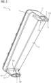
- the automation component 10 for industrial automation is shown.
- the automation component 10 is designed as an I/O peripheral module.
- the automation component 10 has a housing 3 comprising an upper part 1 and a lower part 2, wherein the upper part 1 and the lower part 2 are designed such that for fastening the automation component 10 to a mounting surface 4 of the housing 3, the housing 3 has a first fastening opening 21 and a second fastening opening 22.
- the automation component 10 has a first to eighth I/O connection I1,...,I8 for communication with sensors or actuators, for example using the I/O-Link protocol.
- I1 I/O connection
- I8 I/O connection
- a second Profinet port P2 is used to connect additional automation components to the Profinet.
- the lower part 2 has a first foot 11 and a second foot 12, wherein the feet 11, 12 are formed integrally with the lower part 2.
- the first fastening opening 21 runs through the first foot 11 and the second fastening opening 22 runs through the second foot 12.
- the first foot 11 and the second foot 12 have a fastening area 11a and 12a, respectively, for fastening to the mounting surface 4.
- a contact surface 11b and 12b respectively, is arranged within the fastening area 11a, 12a.
- a hole L in the first fastening opening 21 is in turn arranged within the first contact surface 11b.
- a hole L in the second fastening opening 22 is also arranged in the second contact surface 12b.
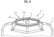
- the contact surfaces 11b, 12b are designed in such a way that they protrude from the respective fastening area 11a, 12a and thereby a recess A is formed which surrounds the contact surface 11b, 12b in a ring shape (this is particularly illustrated with FIG 5 and FIG 8 ).
- a sealing element D is inserted into each of the first foot 11 and the second foot 12.
- the sealing element D is flush with the outer surface of the first foot 11, wherein the sealing element at this point is slightly larger in thickness than the protruding contact surface in order to arrange the sealing element D in a compressed manner between a collar surface KF and the mounting surface 4 in an assembled state, so that a gap-free transition is formed therebetween.
- the FIG 5 shows a detail of the first foot 11 in a cut-out view.
- the first foot 11 has a fastening area 11a for fastening to the mounting surface 4, for this purpose a contact surface 11b is arranged within the fastening area 11a, wherein a hole L of the fastening opening 21 is in turn arranged within the contact surface 11b.
- the contact surface 11b is configured such that it protrudes from the fastening region 11a, thereby forming a recess A that surrounds the contact surface 11b in an annular manner.
- the recess A is thus arranged between the protruding contact surface 11b and an outer edge region RB of the fastening region 11a.
- the outer edge region RB is configured as a circumferential collar K around the recess A, wherein the collar K is arranged lower than the protruding contact surface 11b and has a collar surface KF directed toward the mounting surface 4.
- the annular sealing element D has a sealing lip DL, a first bearing surface A1, and a second bearing surface A2.
- the sealing element D is designed such that the sealing lip DL is arranged as a type of mounting lip in the recess A, the first bearing surface A1 is arranged on the collar surface KF, and the second bearing surface A2 is arranged towards the mounting surface 4, with the sealing element D enclosing the protruding contact surface 11b in an annular manner.
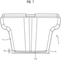
- the sealing element D has a thickness T, wherein the thickness T is selected to be slightly larger than the distance between the collar surface KF and the mounting surface 4, so that in the mounted state the sealing element D is arranged in such a compressed manner between the collar surface KF and the mounting surface 4 that a gap-free transition is formed therebetween.
- FIG 7 once again illustrates the relationship between the thickness T of the sealing element D and the distance TA to the mounting surface 4.
- the FIG 8 shows another perspective view of the first foot 11.
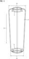
- the housing 3 and thus the upper part 1 and the lower part 2 are designed such that in a preferred installation position VE the first fastening opening 21 is at the top and the second fastening opening 22 is at the bottom.
- the fastening openings 21, 22 are positioned vertically one above the other.
- the housing 3 is tapered from the fastening opening 21 towards the second fastening opening 22.
- a width at the top bo is selected to be greater than a width at the bottom bu. Accordingly, the automation component 10 is wider at the first fastening opening 21 than at the second fastening opening 22. This means that liquids can drain away from the automation component 10 easily and quickly.
- the design of the feet 11, 12 allows for sufficiently good accessibility to all surfaces of the automation module 10 for cleaning, even using low-pressure water and a cleaning cloth.
- This means that the longitudinally extending enclosure between the first foot 11 and the second foot 12 is designed such that the surface of the lower part 2 is spaced from the mounting surface 4 such that a human hand with a cleaning agent can slide through it.
- the housing 3 has a design throughout such that all surfaces, transitions and curves are shaped in such a way that the deposition of contaminants is avoided or minimized.
Landscapes
- Engineering & Computer Science (AREA)
- Microelectronics & Electronic Packaging (AREA)
- Automation & Control Theory (AREA)
- Gasket Seals (AREA)
- Cleaning In General (AREA)
Priority Applications (3)
| Application Number | Priority Date | Filing Date | Title |
|---|---|---|---|
| EP23219354.0A EP4576952A1 (fr) | 2023-12-21 | 2023-12-21 | Composant d'automatisation |
| US18/989,269 US20250210906A1 (en) | 2023-12-21 | 2024-12-20 | Automation Component |
| CN202411894044.3A CN120201668A (zh) | 2023-12-21 | 2024-12-20 | 自动化部件 |
Applications Claiming Priority (1)
| Application Number | Priority Date | Filing Date | Title |
|---|---|---|---|
| EP23219354.0A EP4576952A1 (fr) | 2023-12-21 | 2023-12-21 | Composant d'automatisation |
Publications (1)
| Publication Number | Publication Date |
|---|---|
| EP4576952A1 true EP4576952A1 (fr) | 2025-06-25 |
Family
ID=89308689
Family Applications (1)
| Application Number | Title | Priority Date | Filing Date |
|---|---|---|---|
| EP23219354.0A Pending EP4576952A1 (fr) | 2023-12-21 | 2023-12-21 | Composant d'automatisation |
Country Status (3)
| Country | Link |
|---|---|
| US (1) | US20250210906A1 (fr) |
| EP (1) | EP4576952A1 (fr) |
| CN (1) | CN120201668A (fr) |
Citations (2)
| Publication number | Priority date | Publication date | Assignee | Title |
|---|---|---|---|---|
| US20040246686A1 (en) * | 2003-02-05 | 2004-12-09 | I F M Electronic Gmbh | Electronic module |
| EP2980923A1 (fr) * | 2014-07-30 | 2016-02-03 | Siemens Aktiengesellschaft | Bloc d'automatisation pour l'automatisation industrielle de processus |
-
2023
- 2023-12-21 EP EP23219354.0A patent/EP4576952A1/fr active Pending
-
2024
- 2024-12-20 CN CN202411894044.3A patent/CN120201668A/zh active Pending
- 2024-12-20 US US18/989,269 patent/US20250210906A1/en active Pending
Patent Citations (2)
| Publication number | Priority date | Publication date | Assignee | Title |
|---|---|---|---|---|
| US20040246686A1 (en) * | 2003-02-05 | 2004-12-09 | I F M Electronic Gmbh | Electronic module |
| EP2980923A1 (fr) * | 2014-07-30 | 2016-02-03 | Siemens Aktiengesellschaft | Bloc d'automatisation pour l'automatisation industrielle de processus |
Non-Patent Citations (1)
| Title |
|---|
| -: "Datenblatt BNI IOL-252-000-Z013", 20 December 2023 (2023-12-20), XP093167148, Retrieved from the Internet <URL:https://publications.balluff.com/pdfengine/pdf?type=pdb&id=183266&con=de> [retrieved on 20240527] * |
Also Published As
| Publication number | Publication date |
|---|---|
| US20250210906A1 (en) | 2025-06-26 |
| CN120201668A (zh) | 2025-06-24 |
Similar Documents
| Publication | Publication Date | Title |
|---|---|---|
| DE102017128229B4 (de) | Membranbaugruppe für ein Membranventil sowie Membranventil | |
| EP2443350A1 (fr) | Ensemble de raccordement par encliquetage | |
| WO2009106381A1 (fr) | Capteur de position passif magnétique | |
| WO2023030771A1 (fr) | Dispositif de réception d'un affichage pour un appareil de terrain d'automatisation | |
| DE102016121643A1 (de) | Messanordnung zur Bestimmung und/oder Überwachung zumindest einer Prozessgröße eines Mediums in einer Rohrleitung | |
| EP4028782A1 (fr) | Capteur de courant | |
| EP1699967B1 (fr) | Interface electrique concue pour des appareils menagers conduisant de l'eau | |
| DE202017000744U1 (de) | Schieberanordnung und zugehöriges Federstück | |
| EP4576953A1 (fr) | Composant d'automatisation | |
| EP0959005A3 (fr) | Robinet de dosage | |
| EP4576955A1 (fr) | Composant d'automatisation | |
| DE102008062304A1 (de) | Druckdichte Rohrweiche für Fördergüter | |
| DE102014112116A1 (de) | Vorrichtung zur Überwachung der Lage eines Werkzeugs oder Werkzeugträgers an einer Arbeitsspindel | |
| EP0741811B1 (fr) | Module a outils de tufting | |
| WO2000026930A1 (fr) | Bouton tournant pour l'actionnement de l'organe de reglage d'un potentiometre | |
| DE102004062087A1 (de) | Befestigungsvorrichtung eines Sensors | |
| BE1026757B1 (de) | Baugruppe eines Elektronikgeräts mit einem Gerätegehäuse und einer Elektronikbaugruppe | |
| DE102015226113A1 (de) | Sensorvorrichtung und Sensorsystem | |
| EP3853621B1 (fr) | Pièce moulée destinée à recevoir un élément de concentration de champ magnétique en forme de c, dispositif de concentration de champ magnétique et convertisseur de puissance | |
| WO2004026740A1 (fr) | Dispositif de bifurcation, servant notamment a faire bifurquer des flux de matieres en vrac | |
| DE102024118737B3 (de) | Bauteilanordnung für ein medizinisches Gerät | |
| EP4109046B1 (fr) | Dispositif de mesure de position | |
| EP0965821B1 (fr) | Dispositif de support pour capteur à une prise en rotation | |
| EP1049215A2 (fr) | Connecteur électrique à fiche à angles multiples | |
| DE102014118853A1 (de) | Laborgerät |
Legal Events
| Date | Code | Title | Description |
|---|---|---|---|
| PUAI | Public reference made under article 153(3) epc to a published international application that has entered the european phase |
Free format text: ORIGINAL CODE: 0009012 |
|
| STAA | Information on the status of an ep patent application or granted ep patent |
Free format text: STATUS: THE APPLICATION HAS BEEN PUBLISHED |
|
| AK | Designated contracting states |
Kind code of ref document: A1 Designated state(s): AL AT BE BG CH CY CZ DE DK EE ES FI FR GB GR HR HU IE IS IT LI LT LU LV MC ME MK MT NL NO PL PT RO RS SE SI SK SM TR |
|
| STAA | Information on the status of an ep patent application or granted ep patent |
Free format text: STATUS: REQUEST FOR EXAMINATION WAS MADE |
|
| 17P | Request for examination filed |
Effective date: 20251203 |