EP4578260A1 - Systeme und verfahren zur überwachung und anpassung des betriebs eines landwirtschaftlichen systems - Google Patents
Systeme und verfahren zur überwachung und anpassung des betriebs eines landwirtschaftlichen systems Download PDFInfo
- Publication number
- EP4578260A1 EP4578260A1 EP24221576.2A EP24221576A EP4578260A1 EP 4578260 A1 EP4578260 A1 EP 4578260A1 EP 24221576 A EP24221576 A EP 24221576A EP 4578260 A1 EP4578260 A1 EP 4578260A1
- Authority
- EP
- European Patent Office
- Prior art keywords
- mog
- header
- light
- row unit
- control system
- Prior art date
- Legal status (The legal status is an assumption and is not a legal conclusion. Google has not performed a legal analysis and makes no representation as to the accuracy of the status listed.)
- Pending
Links
Images



Classifications
-
- A—HUMAN NECESSITIES
- A01—AGRICULTURE; FORESTRY; ANIMAL HUSBANDRY; HUNTING; TRAPPING; FISHING
- A01D—HARVESTING; MOWING
- A01D41/00—Combines, i.e. harvesters or mowers combined with threshing devices
- A01D41/12—Details of combines
- A01D41/14—Mowing tables
- A01D41/141—Automatic header control
-
- A—HUMAN NECESSITIES
- A01—AGRICULTURE; FORESTRY; ANIMAL HUSBANDRY; HUNTING; TRAPPING; FISHING
- A01D—HARVESTING; MOWING
- A01D41/00—Combines, i.e. harvesters or mowers combined with threshing devices
- A01D41/12—Details of combines
- A01D41/127—Control or measuring arrangements specially adapted for combines
- A01D41/1271—Control or measuring arrangements specially adapted for combines for measuring crop flow
-
- A—HUMAN NECESSITIES
- A01—AGRICULTURE; FORESTRY; ANIMAL HUSBANDRY; HUNTING; TRAPPING; FISHING
- A01D—HARVESTING; MOWING
- A01D41/00—Combines, i.e. harvesters or mowers combined with threshing devices
- A01D41/12—Details of combines
- A01D41/127—Control or measuring arrangements specially adapted for combines
- A01D41/1271—Control or measuring arrangements specially adapted for combines for measuring crop flow
- A01D41/1272—Control or measuring arrangements specially adapted for combines for measuring crop flow for measuring grain flow
- A01D41/1273—Control or measuring arrangements specially adapted for combines for measuring crop flow for measuring grain flow for measuring grain loss
-
- G—PHYSICS
- G01—MEASURING; TESTING
- G01V—GEOPHYSICS; GRAVITATIONAL MEASUREMENTS; DETECTING MASSES OR OBJECTS; TAGS
- G01V8/00—Prospecting or detecting by optical means
- G01V8/10—Detecting, e.g. by using light barriers
- G01V8/12—Detecting, e.g. by using light barriers using one transmitter and one receiver
-
- A—HUMAN NECESSITIES
- A01—AGRICULTURE; FORESTRY; ANIMAL HUSBANDRY; HUNTING; TRAPPING; FISHING
- A01D—HARVESTING; MOWING
- A01D45/00—Harvesting of standing crops
- A01D45/02—Harvesting of standing crops of maize, i.e. kernel harvesting
- A01D45/021—Cornheaders
-
- A—HUMAN NECESSITIES
- A01—AGRICULTURE; FORESTRY; ANIMAL HUSBANDRY; HUNTING; TRAPPING; FISHING
- A01D—HARVESTING; MOWING
- A01D45/00—Harvesting of standing crops
- A01D45/02—Harvesting of standing crops of maize, i.e. kernel harvesting
- A01D45/028—Harvesting devices mounted to a vehicle
Definitions
- the present invention generally relates to an agricultural system and, more particularly, to operating an agricultural header of the agricultural system to process crop materials.
- a harvester may be used to harvest crops, such as barley, beans, beets, carrots, corn, cotton, flax, oats, potatoes, rye, soybeans, wheat, or other plant crops.
- the harvester may include or be coupled to a header, which may be designed to efficiently harvest certain types of crops.
- a corn header may be designed to efficiently harvest corn.
- the corn header may include row units that include components that operate to separate ears of corn from stalks as the harvester travels through a field.
- a conveyor carries the ears of corn toward processing machinery and/or storage compartments of the harvester, while the stalks are deposited back into the field.
- control system 120 may also analyze the "on" time and the "off' time to determine presence of the stalks between the light emitter and the light detector.
- the presence of the stalks may result in a particular pattern (e.g., a regular pattern or regular intervals, such as occurrence of the "on” time for a first length of time, then occurrence of the "off” time for a second length of time, occurrence of the "on” time for the first length of time, then occurrence of the "off' time for the second length of time, and so on over the time period).
- the presence of the stalks may result in the particular pattern, while the presence of the other MOG (e.g., leaves, husks) may result in the "off' time without the particular pattern (e.g., irregular intervals).
- the other MOG e.g., leaves, husks
- it may be expected or desired that the "off' time due to the presence of the stalks be approximately equal to or less than a third percentage (e.g., 25, 10, or 5 percent) of the time period, or that the "on" time and the "off' time indicate absence of the stalks between the light emitter and the light detector.
- control system 120 may provide outputs (e.g., control signals) based on the sensor data.
- control system 120 may provide the outputs to adjust the travel speed of the agricultural system 100 of FIG. 1 through the field and/or to adjust other components as described in greater detail herein.
- the at least one emitter-detector pair for a respective row unit 204 may include one emitter-detector pair or multiple emitter-detector pairs (e.g., 2, 3, 4, or more) spaced apart along the longitudinal axis 142 or otherwise spaced apart between a forward end portion and a rear end portion of the respective row unit 204.
- the multiple detectors may generate the sensor data that indicates more specific location or depth of the MOG, including the stalks, along the respective row unit 204.
- the control system 120 may process and utilize the sensor data to confirm proper location or depth of MOG, including the stalks, along the respective row unit 204.
- each of the row units 204 of the header 200 may include at least one emitter-detector pair, such that the control system 120 may determine the characteristics of the MOG at each of the row units 204 of the header 200.
- any portion or number of the row units 204 of the header 200 may include at least one emitter-detector pair.
- only one row unit 204 of the header 200 may include at least one emitter-detector pair, wherein the only one row unit 204 is in a middle portion (e.g., a middle row unit) of the header 200 across the width of the header 200.
- the sensor data generated by the light detector of the at least one emitter-detector pair is considered to be indicative of the characteristics of the MOG across the width of the header 200.
- two, three, four, or more row units 204 of the header 200 may each include at least one emitter-detector pair, wherein such row units 204 are distributed across the width of the header 200.
- every other row unit 204 across the width of the header 200 may each include at least one emitter-detector pair, such that the sensor data is indicative of the characteristics of the MOG across the width of the header 200.
- control system 120 may analyze the sensor data on a row unit by row unit basis. In some such cases, the control system 120 may provide the outputs to control the components on a row unit by row unit basis, such as to control respective stalk rollers 210 for a particular row unit 204 based on the sensor data indicative of the MOG at the particular row unit 204. In certain embodiments, the control system 120 may analyze the sensor data for multiple row units 204 (e.g., sensor fusion) across the width of the header 200 to determine the appropriate outputs.
- the control system 120 may provide the outputs to control the components in an effort to reduce the MOG in the rear portions. However, if the sensor data indicates excessive MOG levels in the rear portions of less than half of the row units 204 across the width of the header 200, then the control system 120 may not provide the outputs and may maintain the components to continue the harvesting operations.
- MOG levels e.g., excessive "off" time
- the control system 120 may not provide the outputs and may maintain the components to continue the harvesting operations.
- Embodiments may use machine learning to establish learned relationships between inputs (e.g., sensor data) and outputs (e.g., control signals).
- a trained machine learning model e.g., trained with training data, which may be modeled data, empirical data, or both learns many relationships that may not be readily apparent to a human observer.
- the trained machined learning model can improve result accuracy, particularly for conditions that are not well quantified through a conversion equation.
- the trained machine learning model may have unpredictable and/or dynamic outputs based on the training data.
- the trained machine learning model may be particularly useful for evaluating and responding based on the sensor data collected at multiple row units 204 across the width of the header 200, the sensor data collected over time, and/or the sensor data collected from the one or more sensors 240 and also the one or more sensors 242, 248 of FIG. 2 . Additional examples and control operations are described in greater detail herein.
- the stalk rollers 210 may be controlled to operate (e.g., rotate) at a particular speed to direct the stalk toward the field.
- the control system 120 may control a stalk roller motor 270 to adjust the particular speed at which the stalk rollers 210 rotate, such as based on the sensor data received from the sensor system, as described in greater detail herein.
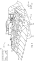
- Each row unit 204 also includes deck plates 212 that are positioned over (e.g., above) the pair of stalk rollers 210 relative to the vertical axis 144.
- Each deck plate 212 extends from a first end to a second end along the longitudinal axis 142, and the deck plates 212 are separated from one another along the lateral axis 140 to define the gap 214.
- the deck plates 212 are spaced apart so that a width of the gap 214 along the lateral axis 140 is sized to enable the stalk and the other MOG to move through the gap 214, but to block the portion of the crop (e.g., ear of corn) from moving or falling through the gap 214.
- the deck plates 212 may receive the portion of the crop (e.g., ear of corn) and block entry of the portion of the crop (e.g., ear of corn) through the gap 214.
- the control system 120 may control an actuator 268 to adjust the deck plates 212 toward and away from one another along the lateral axis 140 to change the width of the gap 214, as described in greater detail herein.
- each row unit 204 may include a pair of chains 216 (e.g., with lugs) that are configured to drive or push the portion of the crop (e.g., ear of corn) along the pair of deck plates 212 toward the conveyor 206.
- a respective hood 250 is positioned rearward of each divider 202 relative to the direction of travel 146 and between adjacent row units 204 to cover various components, such as an actuator that drives the deck plates 212, linkages, and so forth.
- the portion of the crop e.g., ear of corn
- both the stalk and the portion of the crop may pass through the gap 214 and may be discharged from the header 200 before being directed to the conveyor 206, thereby resulting in product loss (e.g., loss of the desirable crop material). If the width of the gap 214 is too small, the stalk may be prevented from passing through the gap 214, and thus the stalk may also be directed toward the conveyor 206, which may be undesirable.
- a variety of operational and/or structural factors such as a ground speed of the header 200, a rotational rate of the stalk rollers 210, and/or the width of the gap 214 between the deck plates 212 (e.g., relative to a size of the portion of the crop and the stalk), may cause undesirable levels of the MOG at the conveyor 206.
- the width of the gap 214 may be sized such that excessive butt-shelling occurs.
- butt-shelling may refer to individual kernels or particles of a crop being dislodged from the crop as the crop strikes or engages with the deck plates 212.
- the butt-shelling may be a result of, and/or may be affected by, a velocity at which the crop strikes the deck plates 212.
- butt-shelling may occur when the width of the gap 214 is sized such that only a portion of the portion of the crop (e.g., the ear of corn) may pass through the gap 214 without interference, while different portions of the portion of the crop engage with the deck plates 212.
- a variety of operational and/or structural factors such as a ground speed of the header 200, a rotational rate of the pair of stalk rollers 210, and/or the width of the gap 214 between the deck plates 212 (e.g., relative to a size of the portion of the crop), may cause butt-shelling and/or affect a rate of butt-shelling.
- Another factor for good harvesting performance is the speed at which the stalk rollers 210 direct the stalk and the portion of the crop toward the deck plates 212. For example, if the speed of the stalk rollers 210 is too high (e.g., too fast), the impact force from the portion of the crop striking the deck plates 212 as the stalk is directed through the gap 214 may be sufficient to cause kernels to dislodge from the portion of the crop (e.g., butt-shelling).
- the speed of the pair of stalk rollers 210 is too low (e.g., too slow), reduced efficiency associated with harvesting a field may occur, thereby resulting in increased costs (e.g., more gas, more time for operators to harvest a field) associated with harvesting (e.g., fuel costs increase as equipment is running for longer amount of time, an amount of time that a farmer spends on a harvester may be increased, thereby resulting in less time to perform other harvesting operations).
- a target speed e.g., speed or speed range
- control system 120 may receive the sensor data from the one or more sensors 240, 242, 248 and analyze the sensor data (e.g., via the trained machine learning model) to determine the characteristics of the MOG and/or the amount of butt-shelling. Further, the control system 120 may determine (e.g., via the trained machine learning model) the appropriate outputs to adjust the components, such as to adjust the width of the gap 214, the rotation rate of the stalk rollers 210, the travel speed of the header 200, the position and/or the orientation of the header 200, or any combination thereof.
- control system 120 may receive the sensor data from the one or more sensors 240, wherein the sensor data is indicative of excessive or undesirable "on" time, as well as excessive or undesirable level of stalks at the at least one emitter-detector pair for at least one row unit 204. Additionally, the control system 120 may receive the sensor data from the one or more sensors 242 of FIG. 2 , wherein the sensor data is indicative of excessive MOG along the conveyor 206. Additionally, the control system 120 may receive the sensor data from the one or more sensors 248, wherein the sensor data is expected or acceptable level of butt-shelling.
Landscapes
- Life Sciences & Earth Sciences (AREA)
- Environmental Sciences (AREA)
- Physics & Mathematics (AREA)
- General Life Sciences & Earth Sciences (AREA)
- General Physics & Mathematics (AREA)
- Geophysics (AREA)
- Management, Administration, Business Operations System, And Electronic Commerce (AREA)
Applications Claiming Priority (1)
| Application Number | Priority Date | Filing Date | Title |
|---|---|---|---|
| US202363615322P | 2023-12-28 | 2023-12-28 |
Publications (1)
| Publication Number | Publication Date |
|---|---|
| EP4578260A1 true EP4578260A1 (de) | 2025-07-02 |
Family
ID=93925700
Family Applications (1)
| Application Number | Title | Priority Date | Filing Date |
|---|---|---|---|
| EP24221576.2A Pending EP4578260A1 (de) | 2023-12-28 | 2024-12-19 | Systeme und verfahren zur überwachung und anpassung des betriebs eines landwirtschaftlichen systems |
Country Status (2)
| Country | Link |
|---|---|
| US (1) | US20250212728A1 (de) |
| EP (1) | EP4578260A1 (de) |
Families Citing this family (1)
| Publication number | Priority date | Publication date | Assignee | Title |
|---|---|---|---|---|
| US20240125661A1 (en) * | 2022-10-14 | 2024-04-18 | Cnh Industrial America Llc | Damping systems and methods for impact sensing on an agricultural header |
Citations (4)
| Publication number | Priority date | Publication date | Assignee | Title |
|---|---|---|---|---|
| EP2702855A1 (de) * | 2012-08-27 | 2014-03-05 | CNH Belgium N.V. | Getreidereiheneinheit |
| US20140331631A1 (en) * | 2011-11-22 | 2014-11-13 | Precision Planting Llc | Stalk sensor apparatus, systems, and methods |
| US20150082760A1 (en) * | 2013-09-23 | 2015-03-26 | Claas Selbstfahrende Erntemaschinen Gmbh | Method for operating a snapping unit having stripper plates with variable spacing |
| EP4360436A1 (de) * | 2022-10-14 | 2024-05-01 | CNH Industrial America LLC | Systeme und verfahren zur ernteguterfassung für einen landwirtschaftlichen erntevorsatz |
-
2024
- 2024-12-19 EP EP24221576.2A patent/EP4578260A1/de active Pending
- 2024-12-23 US US19/000,133 patent/US20250212728A1/en active Pending
Patent Citations (4)
| Publication number | Priority date | Publication date | Assignee | Title |
|---|---|---|---|---|
| US20140331631A1 (en) * | 2011-11-22 | 2014-11-13 | Precision Planting Llc | Stalk sensor apparatus, systems, and methods |
| EP2702855A1 (de) * | 2012-08-27 | 2014-03-05 | CNH Belgium N.V. | Getreidereiheneinheit |
| US20150082760A1 (en) * | 2013-09-23 | 2015-03-26 | Claas Selbstfahrende Erntemaschinen Gmbh | Method for operating a snapping unit having stripper plates with variable spacing |
| EP4360436A1 (de) * | 2022-10-14 | 2024-05-01 | CNH Industrial America LLC | Systeme und verfahren zur ernteguterfassung für einen landwirtschaftlichen erntevorsatz |
Also Published As
| Publication number | Publication date |
|---|---|
| US20250212728A1 (en) | 2025-07-03 |
Similar Documents
| Publication | Publication Date | Title |
|---|---|---|
| US12406387B2 (en) | Crop residue based field operation adjustment | |
| EP3284334B1 (de) | Kornverlustsensoranordnung für eine erntemaschine | |
| EP3672391B1 (de) | Verstellbares gebläse auf der grundlage des korndurchsatzes | |
| US10905045B2 (en) | Automatic chopper pan control | |
| US20250287871A1 (en) | Grain loss detectors for a combine harvester | |
| EP4360436A1 (de) | Systeme und verfahren zur ernteguterfassung für einen landwirtschaftlichen erntevorsatz | |
| EP4570052A1 (de) | Systeme und verfahren zur steuerung eines maispflückers | |
| EP4578260A1 (de) | Systeme und verfahren zur überwachung und anpassung des betriebs eines landwirtschaftlichen systems | |
| EP4353063A1 (de) | Systeme und verfahren zur erkennung von ernteverlusten in einem maispflücker | |
| EP4529758A1 (de) | System und verfahren zur erkennung von erntegutverlusten durch bildgebungsverarbeitung | |
| EP4356712A1 (de) | Maispflückerhöhensteuerungssystem | |
| EP4353062A1 (de) | Aufprallerfassungssysteme und verfahren für einen landwirtschaftlichen erntevorsatz | |
| BR102024027227A2 (pt) | Sistemas e métodos para monitorar e ajustar a operação de um sistema agrícola | |
| EP4353069B1 (de) | Stoppelneigungserkennungssystem für eine landwirtschaftliche erntemaschine | |
| EP4360435A1 (de) | Systeme und verfahren zur anpassung des betriebs eines landwirtschaftlichen systems | |
| EP4353070B1 (de) | Dämpfungssysteme und verfahren zur aufprallerfassung auf einem landwirtschaftlichen erntevorsatz | |
| US20250000024A1 (en) | Corn ear size detection | |
| EP4487673A1 (de) | System und verfahren zur steuerung von deckplatten über mittels bildgebungsverarbeitung gemessene erntegutgeometrien | |
| WO2024015556A1 (en) | Systems and methods for header height control |
Legal Events
| Date | Code | Title | Description |
|---|---|---|---|
| PUAI | Public reference made under article 153(3) epc to a published international application that has entered the european phase |
Free format text: ORIGINAL CODE: 0009012 |
|
| STAA | Information on the status of an ep patent application or granted ep patent |
Free format text: STATUS: THE APPLICATION HAS BEEN PUBLISHED |
|
| AK | Designated contracting states |
Kind code of ref document: A1 Designated state(s): AL AT BE BG CH CY CZ DE DK EE ES FI FR GB GR HR HU IE IS IT LI LT LU LV MC ME MK MT NL NO PL PT RO RS SE SI SK SM TR |
|
| STAA | Information on the status of an ep patent application or granted ep patent |
Free format text: STATUS: REQUEST FOR EXAMINATION WAS MADE |
|
| 17P | Request for examination filed |
Effective date: 20260102 |