EP4578308A1 - Ensemble de chauffage et dispositif de génération d'aérosol - Google Patents
Ensemble de chauffage et dispositif de génération d'aérosol Download PDFInfo
- Publication number
- EP4578308A1 EP4578308A1 EP24795578.4A EP24795578A EP4578308A1 EP 4578308 A1 EP4578308 A1 EP 4578308A1 EP 24795578 A EP24795578 A EP 24795578A EP 4578308 A1 EP4578308 A1 EP 4578308A1
- Authority
- EP
- European Patent Office
- Prior art keywords
- heating
- heat
- pipe
- zone
- aerosol generation
- Prior art date
- Legal status (The legal status is an assumption and is not a legal conclusion. Google has not performed a legal analysis and makes no representation as to the accuracy of the status listed.)
- Pending
Links
Images






Classifications
-
- A—HUMAN NECESSITIES
- A24—TOBACCO; CIGARS; CIGARETTES; SIMULATED SMOKING DEVICES; SMOKERS' REQUISITES
- A24F—SMOKERS' REQUISITES; MATCH BOXES; SIMULATED SMOKING DEVICES
- A24F40/00—Electrically operated smoking devices; Component parts thereof; Manufacture thereof; Maintenance or testing thereof; Charging means specially adapted therefor
- A24F40/40—Constructional details, e.g. connection of cartridges and battery parts
- A24F40/46—Shape or structure of electric heating means
-
- A—HUMAN NECESSITIES
- A24—TOBACCO; CIGARS; CIGARETTES; SIMULATED SMOKING DEVICES; SMOKERS' REQUISITES
- A24F—SMOKERS' REQUISITES; MATCH BOXES; SIMULATED SMOKING DEVICES
- A24F40/00—Electrically operated smoking devices; Component parts thereof; Manufacture thereof; Maintenance or testing thereof; Charging means specially adapted therefor
- A24F40/40—Constructional details, e.g. connection of cartridges and battery parts
- A24F40/48—Fluid transfer means, e.g. pumps
- A24F40/485—Valves; Apertures
-
- A—HUMAN NECESSITIES
- A24—TOBACCO; CIGARS; CIGARETTES; SIMULATED SMOKING DEVICES; SMOKERS' REQUISITES
- A24F—SMOKERS' REQUISITES; MATCH BOXES; SIMULATED SMOKING DEVICES
- A24F40/00—Electrically operated smoking devices; Component parts thereof; Manufacture thereof; Maintenance or testing thereof; Charging means specially adapted therefor
- A24F40/20—Devices using solid inhalable precursors
Definitions
- Heat-not-burn aerosol generation devices are gaining increasing attention and favor due to their advantages of safety, convenience, health, and environmental friendliness. These devices generate aerosol by heating and baking various forms of aerosol generation substrates and deliver the aerosol to users for inhalation. This "heat-not-burn" method ensures that the aerosol generation substrate is heated at a relatively low temperature without combustion and without producing an open flame, effectively avoiding the generation of harmful substances caused by the aerosol generation substrate.
- the objective of the present application is to provide a heating assembly that forms relatively independent heating zones to avoid excessively high heating temperatures that produce high-temperature aerosol, thereby improving user experience.
- the present application aims to provide an aerosol generation device using the aforementioned heating assembly.
- an embodiment provides a heating assembly including a heating element configured to heat an aerosol generation substrate, where the heating element includes at least two heating zones.
- a thermal barrier structure is provided between at least one pair of adjacent heating zones, the thermal barrier structure being configured to reduce heat transfer between the adjacent heating zones.
- the heating element includes at least two heating zones, and a thermal barrier structure is provided between at least one pair of adjacent heating zones.
- the thermal barrier structure is used to prevent heat conduction between adjacent heating zones, reducing the heat transfer speed between different heating zones, improving the thermal insulation performance between adjacent heating zones, and forming relatively independent heating zones between adjacent heating zones. This allows for selective heating of the heating zones as needed, thereby helping to reduce the overall temperature of the heating element and consequently lowering the temperature of the aerosol generated by the aerosol generation substrate, improving user experience.
- the heating element uses an insulating body embedded in the heat-insulating zone to separate different heating zones, employing physical blocking to prevent heat transfer between the heating zones.
- the heating element heats a certain heating zone, the heat transfer from that heating zone to other heating zones is reduced, achieving localized heating of the aerosol generation substrate.
- local heating can be controlled, and the temperature of the aerosol will not be too high, allowing the user to feel a lower temperature during the first few puffs, reducing the risk of burning the mouth and improving user experience.
- the heating element includes a heating pipe configured to heat the aerosol generation substrate.
- the pipe wall of the heating pipe includes at least two heating zones, each capable of heating the aerosol generation substrate.
- a thermal insulation interval is provided between adjacent heating zones to prevent heat transfer between the adjacent heating zones, with the thermal insulation interval penetrating the pipe wall of the heating pipe in the radial direction.
- the heating zones form the heating zones, and the thermal insulation interval forms the thermal barrier structure.
- the heating assembly includes a thermoplastic sealing layer provided on the heating pipe and covering the thermal insulation interval to prevent airflow within the heating pipe from flowing out through the thermal insulation interval.
- the thermal insulation interval is used to prevent heat conduction between adjacent heating zones, reducing the heat transfer speed between different heating zones. Consequently, when the heating requirements of adjacent heating zones differ, mutual influence is minimized, and heat loss is reduced. Meanwhile, by covering the thermal insulation interval with a thermoplastic sealing layer, airflow within the heating pipe is prevented from flowing out through the thermal insulation interval, further reducing heat loss.
- the heating element includes a thermally conductive pipe and electric heating elements provided on the thermally conductive pipe.
- the thermally conductive pipe has a heating chamber for inserting the aerosol generation substrate, and the pipe wall of the thermally conductive pipe includes at least two heating zones.
- the number of electric heating elements is at least two, with each heating zone corresponding to at least one electric heating element, and the electric heating element is configured to heat the corresponding heating zone.
- a pipe wall thinning portion is provided on the pipe wall of the thermally conductive pipe between at least one pair of adjacent heating zones, and the wall thickness of the pipe wall thinning portion is less than the wall thickness of the heating zones.
- the heating zones form the heating zones, and the pipe wall thinning portion forms the thermal barrier structure.
- the pipe wall thinning portion slows down the heat transfer speed between adjacent heating zones.
- the heat is more concentrated in the heated area of the working heating zone, resulting in higher heat utilization efficiency, less heat loss, and improved independent heating efficiency of the heating zones.
- connection and “couple” in the present application, unless otherwise specified, include both direct and indirect connections (couplings).
- the heating assembly includes a heating element configured to heat an aerosol generation substrate, and the heating element includes at least two heating zones.
- a thermal barrier structure is provided between at least one pair of adjacent heating zones, the thermal barrier structure being configured to prevent heat transfer between the adjacent heating zones.
- the heating assembly is an aerosol generation substrate heating assembly.
- the aerosol generation device includes a power supply and the heating assembly, with the power supply powering the heating assembly.
- the aerosol generation device is also referred to as an aerosol generation device, an electronic atomizer, or an atomization device.
- the present application provides a heating assembly and an aerosol generation device, where the heating assembly is applied to the aerosol generation device.
- the aerosol generation device can generate aerosol by heating the aerosol generation substrate, which is a colloidal dispersion system where solid or liquid particles are dispersed and suspended in a gaseous medium.
- the aerosol generation device generates aerosol by heating the aerosol generation substrate without combustion, utilizing a special heat source to heat the aerosol generation substrate.
- various substances in the aerosol generation substrate volatilize to produce aerosol, without open flame generation, making it environmentally friendly and providing a good user experience while reducing harmful substances produced by high-temperature pyrolysis of conventional atomization substrates during combustion.
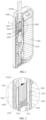
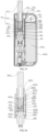
- the heating assembly provided in this embodiment includes: a thermally conductive body 1010, a heating structure 1020, and a heat exchange structure 1030.
- the thermally conductive body 1010 forms an open-ended accommodating cavity 1011, with axially distributed first thermal conductive zone 1012 and second thermal conductive zone 1013.
- the portion of the accommodating cavity 1011 corresponding to the first thermal conductive zone 1012 is for inserting the aerosol generation substrate 10100.
- the heat exchange structure 1030 is mounted at the portion of the accommodating cavity 1011 corresponding to the second thermal conductive zone 1013.
- the heating structure 1020 is positioned at the first thermal conductive zone 1012, generating heat.
- the first thermal conductive zone 1012 conducts heat generated by the heating structure 1020 to the second thermal conductive zone 1013, and the heat exchange structure 1030 is configured to perform heat exchange with the second thermal conductive zone 1013 to preheat incoming gas.
- the present application provides a heating assembly 2010, which can be specifically used to accommodate the aerosol generation substrate 2020 and heat the aerosol generation substrate 2020 when electrified.
- the aerosol generation substrate 2020 can specifically include plant leaf substrates, such as tobacco substrates.
- the aerosol generation substrate 2020 can also include a protective sleeve, which can wrap the plant leaf substrate, for example, the plant leaf substrate can be wrapped inside aluminum foil or paper for use.
- the heating assembly 2010 includes a heating element 2011 and a thermal insulation body 2012.
- the heating element 2011 is used to accommodate the aerosol generation substrate 2020 and includes a heating material.
- the heating element 2011 can support the aerosol generation substrate 2020 accommodated therein and can generate heat when electrified to heat the aerosol generation substrate 2020 accommodated therein, thereby forming an aerosol for user use.
- the heating element 2011 can be entirely made of conductive material, such as conductive ceramics, or it can include an insulating substrate and a conductive heating layer provided on the surface of the insulating substrate.
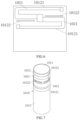
- the heating element 2011 includes a substrate 20111 and a heating layer 20112.
- the heating layer 20112 is used to generate heat when electrified to heat the aerosol generation substrate 2020. Both ends of the heating layer 20112 can be connected to two electrodes 20113, which can be electrically connected to the power supply assembly 2040 and the controller 2050 through external wires.
- the electrodes 20113 can be conductive coatings applied to the substrate 20111, such as metal coatings, conductive silver paste, or conductive tape, etc., or they can be metal conductive sheets provided on the substrate 20111 or metals deposited on the substrate 20111, such as gold film, aluminum film, or copper film, etc.
- the heating element 2011 can be a tubular structure.
- the substrate 20111 is a cylindrical tubular structure, and the accommodating cavity 201111 is also cylindrical, with the wall thickness of the side wall of the substrate 20111 being a fixed value, allowing the heating element 2011 to heat the aerosol generation substrate 2020 evenly.
- the heating element 2011 has a heat-insulating zone 20114 and at least two independent heating zones 20115.
- the independent heating zones 20115 refer to each heating zone 20115 being capable of heating independently.
- the heat-insulating zone 20114 is provided between two adjacent heating zones 20115, and the thermal insulation body 2012 is embedded in the heat-insulating zone 20114 to block heat transfer between the adjacent heating zones 20115.
- the number of heating zones 20115 is the same as the number of heating layers 20112, and the heating zones 20115 correspond one-to-one with the heating layers 20112, meaning one heating layer 20112 corresponds to one heating zone 20115.
- At least part of the thermal insulation body 2012 is provided between two adjacent heating layers 20112 to block heat transfer between the two adjacent heating layers 20112. It can be as shown in FIGs. 9-11 , where the entire thermal insulation body 2012 is provided between two adjacent heating layers 20112, or it can be a section of the thermal insulation body 2012 provided between two adjacent heating layers 20112.
- the material of the thermal insulation body 2012 needs to meet the conditions of high-temperature resistance and low thermal conductivity.
- the thermal conductivity of the thermal insulation body 2012 is less than 8W/(m•K)
- the material of the thermal insulation body 2012 includes at least one of microcrystalline glass, zirconia ceramics, polyether ether ketone, and polyimide.
- the heating element 2011 of the present application uses the thermal insulation body 2012 embedded in the heat-insulating zone 20114 to separate different heating zones 20115, using physical blocking to prevent heat transfer between the heating zones 20115. Therefore, when the heating element 2011 heats in a certain heating zone 20115, the heat transfer from that heating zone 20115 to other heating zones 20115 is reduced, thereby achieving local heating of the aerosol generation substrate 2020. During the first few puffs of the user, local heating can be controlled, and the temperature of the aerosol will not be too high, allowing the user to feel a lower temperature during the first few puffs, reducing the risk of burning the mouth and improving the user experience.
- some existing heating assemblies 2010 set two heating elements, meaning the existing independent heating zones 20115 are respectively set on two heating elements, and the two heating elements are respectively connected to the two ends of the thermal insulation body to achieve thermal insulation.
- the existing structure has more parts, the assembly steps are cumbersome, and the reliability of the connection strength of the two heating elements fixedly connected by the thermal insulation body is poor.
- the independent heating zones 20115 and the heat-insulating zone 20114 in the present application are all set on the same heating element, and the heat-insulating zone 20114 achieves thermal insulation by embedding the thermal insulation body 2012.
- the thermal insulation body 2012 is embedded in the heating element 2011, which does not excessively affect the structural strength of the heating element 2011, and the reliability of the structural strength of the heating element 2011 is strong.
- the heat-insulating zone 20114 has a hollow structure 201141, and the thermal insulation body 2012 can be filled in the hollow structure 201141.
- the hollow structure 201141 refers to a through groove or through hole in the heat-insulating zone 20114 that penetrates the side wall of the heating element 2011 along the thickness direction of the heating element 2011.
- the thermal insulation body 2012 can be filled in the hollow structure 201141 through processes such as coating, spraying, or dispensing.
- the hollow structure 201141 prevents energy diffusion between different heating zones 20115 through physical blocking, improving the independence of each heating zone 20115.
- the thermal insulation body 2012 filled in the hollow structure 201141 can maintain a certain degree of sealing of the heating element 2011, making it difficult for the aerosol generated by the heating element 2011 to escape from the hollow structure 201141, improving energy utilization efficiency.
- the hollow structure 201141 can be an insulating hole 201141a, which is a linear hole structure.
- the insulating hole 201141a can also be a bent structure, a zigzag structure, or other regular or irregular shapes.
- the hollow structure 201141 can be an intermittently spaced hollow structure 201141.
- the hollow structure 201141 includes multiple intermittently spaced insulating holes 201141a. Setting the hollow structure 201141 as intermittently spaced can improve the structural strength of the heat-insulating zone 20114 compared to a continuous hollow structure 201141.
- each heating zone 20115 is arranged in parallel along the circumferential direction of the heating element 2011, and the insulating hole 201141a can extend along the axial direction to block adjacent heating zones 20115.
- each heating zone 20115 can also be arranged in parallel along the axial direction of the heating element 2011, and the insulating hole 201141a can extend along the circumferential direction to block adjacent heating zones 20115.
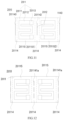
- the heating element 2011 has a first heating zone 201151 and a second heating zone 201152.
- the number of heat-insulating zones 20114 is two, and the number of insulating holes 201141a is two, namely the first insulating hole 201142 and the second insulating hole 201143. Both the first insulating hole 201142 and the second insulating hole 201143 extend along the axial direction.
- the first heating zone 201151 has opposite first and second ends along the circumferential direction
- the second heating zone 201152 has opposite first and second ends along the circumferential direction. The first end of the first heating zone 201151 is close to the second end of the second heating zone 201152.
- the first insulating hole 201142 is provided between the first end of the first heating zone 201151 and the second end of the second heating zone 201152, and the second insulating hole 201143 is provided between the second end of the first heating zone 201151 and the first end of the second heating zone 201152.
- the heat-insulating zone 20114 may not have a hollow structure 201141, and the heat-insulating zone 20114 has a groove, which is a blind groove, with the thermal insulation body 2012 provided in the groove.
- the groove structure of the heat-insulating zone 20114 can better prevent aerosol leakage, maintaining better sealing of the heating element 2011.
- the heat-insulating zone 20114 can include both a hollow structure 201141 and a groove.
- the heating assembly 2010 further includes a housing assembly 2013, a thermal insulation layer 2014, a flow guide 2015, and a heat exchange core 2016.
- the housing assembly 2013 includes an upper housing 20131 and a lower housing 20132.
- the upper housing 20131 has an installation cavity 201311 and an insertion passage 201312.
- the insertion passage 201312 is provided at one end of the installation cavity 201311 and communicates with the installation cavity 201311.
- the lower housing 20132 is provided at the end of the installation cavity 201311 away from the insertion passage 201312 and blocks the end of the installation cavity 201311 away from the insertion passage 201312.
- the heating element 2011 is provided in the installation cavity 201311, and one end of the heating element 2011 close to the lower housing 20132 is detachably connected to the lower housing 20132.
- the end of the heating element 2011 close to the insertion passage 201312 is detachably connected to the side wall of the insertion passage 201312.
- the aerosol generation substrate 2020 is inserted into the accommodating cavity 201111 of the heating element 2011 through the insertion passage 201312.
- the lower housing 20132 has an air intake channel 201321, which communicates with the air intake port of the heating assembly 2010.
- the airflow enters the air intake channel 201321 of the lower housing 20132 from the air intake port of the heating assembly 2010 and flows into the heating element 2011 from the air intake channel 201321.
- the heating element 2011 heats the aerosol generation substrate 2020 to generate aerosol, which flows out from the air outlet of the heating assembly 2010 for user use.
- the present application adds a flow guide 2015, which guides the hot airflow into the central area of the aerosol generation substrate 2020 through the flow guide 2015, allowing the hot airflow to carry out the nicotine in the central area of the aerosol generation substrate 2020, thereby achieving a gradual release process of nicotine, improving the uniformity of suction, and extending the use time of the aerosol generation substrate 2020, enhancing the user experience.
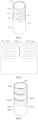
- the heating pipe 302 has a heating chamber 3021 for inserting the aerosol generation substrate 301 to heat the aerosol generation substrate 301 (please refer to FIG. 17 ).
- both ends of the heating pipe 302 are open, with one end of the heating pipe 302 being the insertion end 3022 for inserting the aerosol generation substrate 301, and the other end being the ventilation end 3023 for airflow to enter the heating pipe 302.
- the heating pipe 302 can use any feasible method.
- the wall of the heating pipe 302 includes at least two heating zones 3024, each heating zone 3024 being capable of heating the aerosol generation substrate 301 inserted into the heating chamber 3021.
- a thermal insulation interval 3025 is provided between adjacent heating zones 3024 to prevent heat transfer between the adjacent heating zones 3024.
- the thermal insulation interval 3025 penetrates the wall of the heating pipe 302 in the radial direction.
- the thermal insulation interval 3025 is transparent in the thickness direction of the wall of the heating pipe 302, meaning that the thermal insulation interval is a hollow structure for blocking heat transfer.
- the thermal insulation interval 3025 can reduce heat transfer between adjacent heating zones 3024, reducing heat loss.
- the heating zones 3024 on the heating pipe 302 can independently heat the aerosol generation substrate 301. In actual use, it is not limited to only part of the heating zones 3024 being turned on for heating. According to actual needs, all heating zones 3024 can be turned on for heating at the same time, in which case the heating pipe 302 as a whole heats the aerosol generation substrate 301.
- a heating strategy for the aerosol generation substrate 301 is as follows.
- the aerosol generated after heating contains water vapor. If the temperature of the aerosol is too high at this time, the water vapor can easily burn the mouth when inhaling the aerosol. Therefore, when starting to heat the aerosol generation substrate 301, only part of the heating zones 3024 is used to heat the aerosol generation substrate 301. After the moisture in the aerosol generation substrate 301 is expelled, all heating zones 3024 work simultaneously, and the heating pipe 302 as a whole heats the aerosol generation substrate 301.
- heating zones 3024 on the heating pipe 302 can use any feasible form.
- the heating zones 3024 are arranged in the circumferential direction of the heating pipe 302; for example, the heating zones 3024 can also be arranged in the axial direction of the heating pipe 302; and for example, there are four or more heating zones 3024, with at least two arranged in the circumferential direction of the heating pipe 302 and at least two arranged in the axial direction of the heating pipe 302.
- the thermal insulation interval 3025 can be arranged in any feasible manner.
- a straight-line thermal insulation interval 3025 can be used; multiple thermal insulation intervals 3025 can be arranged in a continuous interval, in which case the blocking interval can be in a strip shape, square shape, circular shape, or any shape; and a curved thermal insulation interval 3025 can also be used.
- the material of the heat-shrinkable sealing layer is required to be heat-resistant above 250°C.
- this heat resistance requirement can be reduced or increased.
- the electric heating element 303 is fixed on the outer surface of the heating pipe 302, making it less likely to separate from the heating pipe 302 and more convenient for the thermoplastic sealing layer 304 to be heat-shrunk on the heating pipe 302.
- the electric heating element 303 is a heating film formed on the outer surface of the heating pipe 302, in which case the electric heating element 303 and the heating pipe 302 together form a thick film pipe, with an insulating layer outside the heating film, and the heating pipe 302 uses a metal pipe with good thermal conductivity.
- the electric heating element 303 can also be embedded in the heating pipe 302 or a heating wire wound on the outer peripheral surface of the heating pipe 302.
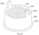
- a heat exchanger 305 is provided inside the airflow heating section 3026, and the airflow heating section 3026 is in thermal contact with the heat exchanger 305.
- the heat exchanger 305 has multiple airflow channels 3051, which allow airflow to pass through to heat the passing airflow. By uniformly heating the airflow through the heat exchanger 305, the airflow heating efficiency is improved.
- the airflow channels 3051 of the heat exchanger 305 extend along the axial direction of the heating pipe 302, and multiple airflow channels 3051 are evenly spaced. In some other embodiments, the heat exchanger 305 may not be provided, in which case the airflow is directly heated after passing through the airflow heating section 3026.
- the generation stick blocking structure is a flow guide seat 306 located on one side of the heat exchanger 305.
- the flow guide seat 306 has a generation stick blocking surface 3061 for blocking cooperation with the aerosol generation substrate 301.
- the generation stick blocking surface 3061 is located on the side of the flow guide seat 306 facing away from the heat exchanger 305.
- the center of the flow guide seat 306 has a flow guide hole 3062, which is used to guide airflow into the aerosol generation substrate 301 from the center of the end face of the aerosol generation substrate 301.
- an annular protrusion can be provided in the heating pipe 302 to block the end face of the aerosol generation substrate 301.
- the heat exchanger 305 can also form a generation stick blocking structure, blocking the end face of the aerosol generation substrate 301.
- FIGs. 15 and 16 are both interference-fitted in the heating pipe 302.
- the aerosol generation substrate heating assembly includes a first heating pipe seat 307 and a second heating pipe seat 308.
- the heating pipe 302 is clamped between the first heating pipe seat 307 and the second heating pipe seat 308.
- the first heating pipe seat 307 has a first pipe seat hole 3071 for the aerosol generation substrate 301 to pass through and insert into the heating chamber 3021.
- the second heating pipe seat 308 has a second pipe seat hole 3081 for the airflow entering the aerosol generation substrate 301 to pass through.
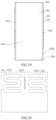
- At least one pair of adjacent heating zones 3024 has a pipe wall thinning portion 3028 provided on the wall of the heating pipe 302.
- the wall thickness of the pipe wall thinning portion 3028 is less than the wall thickness of the heating zones 3024, allowing the heat conduction speed between adjacent heating zones 3024 to be slowed down.
- the wall thickness of the pipe wall thinning portion 3028 in the present application is less than the wall thickness of the heating zones 3024, allowing the heat conduction speed through the pipe wall thinning portion 3028 to decrease.
- the heat transferred to the non-working heating zone 3024 is reduced, reducing energy waste.
- the temperature of the independently heating working heating zone rises faster, and the heating efficiency is higher.
- each heating zone 3024 can independently heat the aerosol generation substrate 301 inserted into the heating chamber 3021.
- the heating zones include a first heating zone 30241 and a second heating zone 30242.
- the first heating zone 30241 and the second heating zone 30242 are adjacent, with a pipe wall thinning portion 3028 provided between the first heating zone 30241 and the second heating zone 30242.
- the wall thickness of the pipe wall thinning portion 3028 is less than the wall thickness of the first heating zone 30241 and less than the wall thickness of the second heating zone 30242, allowing the heat conduction speed between the first heating zone 30241 and the second heating zone 30242 to be slowed down.
- the wall thickness of the pipe wall thinning portion 3028 in the present application is less than the wall thickness of the first heating zone 30241 and less than the wall thickness of the second heating zone 30242, allowing the heat conduction speed through the pipe wall thinning portion 3028 to decrease.
- the heat transferred to the second heating zone 30242 is reduced.
- the heat transferred to the first heating zone 30241 is reduced, reducing energy waste.
- the temperature of the independently heating working heating zone rises faster, and the heating efficiency is higher.
- the heating zones 3024 on the heating pipe 302 in the present application can independently heat the aerosol generation substrate 301. In actual use, it is not limited to only the first heating zone 30241 or only the second heating zone 30242 being turned on for heating. According to actual needs, the first heating zone 30241 and the second heating zone 30242 can be turned on for heating at the same time, in which case the heating pipe 302 as a whole heats the aerosol generation substrate 301.
- a heating strategy for the aerosol generation substrate 301 is as follows.
- the aerosol generated after heating contains water vapor. If the temperature of the aerosol is too high at this time, the water vapor can easily burn the mouth when inhaling the aerosol. Therefore, when starting to heat the aerosol generation substrate 301, only the first heating zone 30241 is used to heat the aerosol generation substrate 301. After the moisture in the aerosol generation substrate 301 is expelled, the first heating zone 30241 and the second heating zone 30242 work simultaneously, and the heating pipe 302 as a whole heats the aerosol generation substrate 301.
- a heating strategy for the aerosol generation substrate 301 is as follows: arrange the first heating zone 30241 and the second heating zone 30242 vertically, with the first heating zone 30241 heating one section of the aerosol generation substrate 301, and then the second heating zone 30242 heating another section of the aerosol generation substrate 301.
- the first heating zone 30241 and the second heating zone 30242 work in different time periods to heat the aerosol generation substrate 301 in sections, which can extend the number of puffs of the aerosol generation substrate 301.
- the outer side surface of the pipe wall thinning portion 3028 is recessed toward the inside of the heating pipe 302. In some other embodiments, the inner side surface of the pipe wall thinning portion 3028 is recessed toward the outside of the heating pipe 302. In some other embodiments, the outer side surface of the pipe wall thinning portion 3028 is recessed toward the inside of the heating pipe 302, and the inner side surface of the pipe wall thinning portion 3028 is recessed toward the outside of the heating pipe 302.
- the first heating zone 30241 and the second heating zone 30242 are arranged adjacent to each other in the circumferential direction of the heating pipe 302, with the pipe wall thinning portion 3028 extending along the axial direction of the heating pipe 302.
- the arrangement of heating zones 3024 on the heating pipe 302 can use any feasible form.
- the first heating zone 30241 and the second heating zone 30242 can also be arranged adjacent to each other in the axial direction of the heating pipe 302, with the pipe wall thinning portion 3028 extending along the circumferential direction of the heating pipe 302.
- there are four or more heating zones 3024 with at least two arranged adjacent to each other in the circumferential direction of the heating pipe 302 and at least two arranged adjacent to each other in the axial direction of the heating pipe 302.
- the blocking edge 3053 is clamped between the heating pipe 302 and the second heating pipe seat 308.
Landscapes
- Resistance Heating (AREA)
- Instantaneous Water Boilers, Portable Hot-Water Supply Apparatuses, And Control Of Portable Hot-Water Supply Apparatuses (AREA)
Applications Claiming Priority (5)
| Application Number | Priority Date | Filing Date | Title |
|---|---|---|---|
| CN202321010093.7U CN220441923U (zh) | 2023-04-26 | 2023-04-26 | 加热组件和气溶胶产生装置 |
| CN202320979949.5U CN220000826U (zh) | 2023-04-26 | 2023-04-26 | 一种加热组件和电子雾化器 |
| CN202321482372.3U CN220343694U (zh) | 2023-06-12 | 2023-06-12 | 一种用于生成气溶胶的雾化装置及加热组件 |
| CN202321484335.6U CN220343695U (zh) | 2023-06-12 | 2023-06-12 | 气溶胶产生基质加热组件及气溶胶生成装置 |
| PCT/CN2024/078829 WO2024222190A1 (fr) | 2023-04-26 | 2024-02-27 | Ensemble de chauffage et dispositif de génération d'aérosol |
Publications (1)
| Publication Number | Publication Date |
|---|---|
| EP4578308A1 true EP4578308A1 (fr) | 2025-07-02 |
Family
ID=93255510
Family Applications (1)
| Application Number | Title | Priority Date | Filing Date |
|---|---|---|---|
| EP24795578.4A Pending EP4578308A1 (fr) | 2023-04-26 | 2024-02-27 | Ensemble de chauffage et dispositif de génération d'aérosol |
Country Status (3)
| Country | Link |
|---|---|
| EP (1) | EP4578308A1 (fr) |
| JP (1) | JP7850867B2 (fr) |
| WO (1) | WO2024222190A1 (fr) |
Family Cites Families (16)
| Publication number | Priority date | Publication date | Assignee | Title |
|---|---|---|---|---|
| CN108601397A (zh) * | 2015-08-17 | 2018-09-28 | 菲利普莫里斯生产公司 | 气溶胶生成系统和用于这类系统的气溶胶生成制品 |
| JP7528069B2 (ja) * | 2018-10-12 | 2024-08-05 | ジェイティー インターナショナル エスエイ | エアロゾル発生装置及びそのための加熱チャンバ |
| EP3871533B1 (fr) * | 2018-10-26 | 2024-09-11 | Japan Tobacco Inc. | Appareil de chauffage et inhalateur d'arôme qui en est pourvu |
| EP3993651B1 (fr) * | 2019-07-04 | 2023-08-02 | Philip Morris Products S.A. | Agencement de chauffage inductif comprenant un élément de chauffage inductif segmenté perméable aux gaz |
| KR20220058885A (ko) * | 2019-09-06 | 2022-05-10 | 제이티 인터내셔널 소시에떼 아노님 | 박막 히터 |
| CN114727665A (zh) * | 2019-11-18 | 2022-07-08 | 日本烟草国际股份有限公司 | 气溶胶产生制品和气溶胶产生系统 |
| CN216315588U (zh) * | 2021-07-28 | 2022-04-19 | 深圳麦克韦尔科技有限公司 | 一种气溶胶生成制品 |
| EP4404778A1 (fr) * | 2021-09-20 | 2024-07-31 | Nicoventures Trading Limited | Dispositif de fourniture d'aérosol |
| CN216453385U (zh) * | 2021-12-03 | 2022-05-10 | 北京温致科技有限公司 | 发热体及气溶胶生成装置 |
| CN218354679U (zh) * | 2022-08-01 | 2023-01-24 | 深圳麦时科技有限公司 | 气溶胶产生装置及其发热组件 |
| CN115530438A (zh) * | 2022-09-21 | 2022-12-30 | 深圳麦时科技有限公司 | 气溶胶产生装置及其加热装置 |
| CN218354684U (zh) * | 2022-09-27 | 2023-01-24 | 深圳市基克纳科技有限公司 | 一种气溶胶产生装置及其加热结构 |
| CN220441923U (zh) * | 2023-04-26 | 2024-02-06 | 深圳市基克纳科技有限公司 | 加热组件和气溶胶产生装置 |
| CN220343694U (zh) * | 2023-06-12 | 2024-01-16 | 深圳市基克纳科技有限公司 | 一种用于生成气溶胶的雾化装置及加热组件 |
| CN220343695U (zh) * | 2023-06-12 | 2024-01-16 | 深圳市基克纳科技有限公司 | 气溶胶产生基质加热组件及气溶胶生成装置 |
| CN220000826U (zh) * | 2023-04-26 | 2023-11-14 | 深圳市基克纳科技有限公司 | 一种加热组件和电子雾化器 |
-
2024
- 2024-02-27 EP EP24795578.4A patent/EP4578308A1/fr active Pending
- 2024-02-27 JP JP2025514601A patent/JP7850867B2/ja active Active
- 2024-02-27 WO PCT/CN2024/078829 patent/WO2024222190A1/fr not_active Ceased
Also Published As
| Publication number | Publication date |
|---|---|
| JP2025528579A (ja) | 2025-08-28 |
| WO2024222190A1 (fr) | 2024-10-31 |
| JP7850867B2 (ja) | 2026-04-23 |
Similar Documents
| Publication | Publication Date | Title |
|---|---|---|
| JP7591610B2 (ja) | エアロゾル発生装置及びその加熱モジュール | |
| JP7499968B2 (ja) | エアロゾル発生装置 | |
| WO2024055731A1 (fr) | Ensemble de chauffage et dispositif de génération d'aérosol | |
| CN207784280U (zh) | 一种发热体 | |
| JP7835912B2 (ja) | 加熱アセンブリ及びエアロゾル生成装置 | |
| CN220441923U (zh) | 加热组件和气溶胶产生装置 | |
| CN216983602U (zh) | 发热体和气雾生产装置 | |
| CN216135176U (zh) | 一种气溶胶生成制品 | |
| CN216220206U (zh) | 加热组件和气溶胶产生装置 | |
| EP4578308A1 (fr) | Ensemble de chauffage et dispositif de génération d'aérosol | |
| CN216135179U (zh) | 一种气溶胶生成制品 | |
| EP3970529B1 (fr) | Dispositif de récupération d'énergie thermique, et dispositif de chauffage de cigarette électronique de type à chauffage d'air sans contact le comprenant | |
| WO2024055720A1 (fr) | Ensemble de chauffage et dispositif de génération d'aérosol | |
| CN220343695U (zh) | 气溶胶产生基质加热组件及气溶胶生成装置 | |
| CN220343694U (zh) | 一种用于生成气溶胶的雾化装置及加热组件 | |
| CN112244367B (zh) | 一种发热体及其制备方法和具有该发热体的抽烟设备 | |
| CN219108733U (zh) | 热交换器以及电子雾化装置 | |
| CN113598424A (zh) | 一种气溶胶生成制品 | |
| KR20260014007A (ko) | 가열 장치 및 가열식 비연소 흡연 세트 | |
| CN222017726U (zh) | 气溶胶产生装置和加热组件 | |
| WO2024051376A1 (fr) | Ensemble à fumer à chauffage sans combustion | |
| CN103921315B (zh) | 电加热辐射打孔孔隙膜设备及打孔方法 | |
| WO2024008162A1 (fr) | Dispositif de chauffage, dispositif de génération d'aérosol et système de génération d'aérosol | |
| CN217958771U (zh) | 气溶胶产生装置及其加热组件 | |
| CN222340588U (zh) | 气溶胶产生装置及其加热组件 |
Legal Events
| Date | Code | Title | Description |
|---|---|---|---|
| STAA | Information on the status of an ep patent application or granted ep patent |
Free format text: STATUS: THE INTERNATIONAL PUBLICATION HAS BEEN MADE |
|
| PUAI | Public reference made under article 153(3) epc to a published international application that has entered the european phase |
Free format text: ORIGINAL CODE: 0009012 |
|
| STAA | Information on the status of an ep patent application or granted ep patent |
Free format text: STATUS: REQUEST FOR EXAMINATION WAS MADE |
|
| 17P | Request for examination filed |
Effective date: 20250326 |
|
| AK | Designated contracting states |
Kind code of ref document: A1 Designated state(s): AL AT BE BG CH CY CZ DE DK EE ES FI FR GB GR HR HU IE IS IT LI LT LU LV MC ME MK MT NL NO PL PT RO RS SE SI SK SM TR |