EP4578353A1 - Reinigungsvorrichtung - Google Patents
Reinigungsvorrichtung Download PDFInfo
- Publication number
- EP4578353A1 EP4578353A1 EP24196559.9A EP24196559A EP4578353A1 EP 4578353 A1 EP4578353 A1 EP 4578353A1 EP 24196559 A EP24196559 A EP 24196559A EP 4578353 A1 EP4578353 A1 EP 4578353A1
- Authority
- EP
- European Patent Office
- Prior art keywords
- handheld
- cleaning device
- positioning
- device body
- operating handle
- Prior art date
- Legal status (The legal status is an assumption and is not a legal conclusion. Google has not performed a legal analysis and makes no representation as to the accuracy of the status listed.)
- Pending
Links
Images






Classifications
-
- A—HUMAN NECESSITIES
- A47—FURNITURE; DOMESTIC ARTICLES OR APPLIANCES; COFFEE MILLS; SPICE MILLS; SUCTION CLEANERS IN GENERAL
- A47L—DOMESTIC WASHING OR CLEANING; SUCTION CLEANERS IN GENERAL
- A47L5/00—Structural features of suction cleaners
- A47L5/12—Structural features of suction cleaners with power-driven air-pumps or air-compressors, e.g. driven by motor vehicle engine vacuum
- A47L5/22—Structural features of suction cleaners with power-driven air-pumps or air-compressors, e.g. driven by motor vehicle engine vacuum with rotary fans
- A47L5/28—Suction cleaners with handles and nozzles fixed on the casings, e.g. wheeled suction cleaners with steering handle
-
- A—HUMAN NECESSITIES
- A47—FURNITURE; DOMESTIC ARTICLES OR APPLIANCES; COFFEE MILLS; SPICE MILLS; SUCTION CLEANERS IN GENERAL
- A47L—DOMESTIC WASHING OR CLEANING; SUCTION CLEANERS IN GENERAL
- A47L5/00—Structural features of suction cleaners
- A47L5/12—Structural features of suction cleaners with power-driven air-pumps or air-compressors, e.g. driven by motor vehicle engine vacuum
- A47L5/22—Structural features of suction cleaners with power-driven air-pumps or air-compressors, e.g. driven by motor vehicle engine vacuum with rotary fans
- A47L5/24—Hand-supported suction cleaners
Definitions
- the present application relates to the technical field of electrical cleaning devices for household use, and in particular, to a cleaning device.
- the cleaning device there is an air passage in the handheld body, two ends of which form respectively an air inlet located in the center of an end face of the inserting end, and an air outlet located in a side face of the inserting end;
- the device body has an air admission passage and an air discharge passage, an air outlet of the air admission passage being located in the center of the supporting groove and correspondingly in communication with the air inlet, an air inlet of the air discharge passage being located in a side wall of the supporting groove and correspondingly in communication with the air outlet.
- the handheld body comprises a housing, a support, and a driving element used for providing a suction force; the support is partially inserted into the housing and provided inside with a chamber in which the driving element is arranged, at least part of the support and the housing adjacent to the support forming the inserting end.
- the support provides a mounting position for the driving element, and on the other hand, part of the support and the housing adjacent to the support form the inserting end, putting it to multiple uses, which helps reduce costs while causing the overall structure to have a high stability.
- a part of the chamber forms the air passage
- an end face of the support facing the device body forms the end face of the inserting end
- the air inlet corresponds to a suction opening of the driving element
- the air outlet is located in a side face of the support.
- the overall structure is simple and compact, resulting in a high space utilization rate.
- a side face of the support has a slot, an opening of the slot facing a side wall of the supporting groove and forming the air outlet, the slot having a first side wall and a second side wall that are opposite to each other, the first side wall facing the handheld body; the second side wall is provided with at least one through hole that puts the air passage and the slot in communication.
- the first side wall is provided with a notch in communication with an end face of the support facing the device body, so as to cause the opening to have an inclined form.
- a cleaning device comprises a device body and a handheld structure removably connected to the device body.
- the handheld structure is used for providing a suction force and can be used separately after being removed.
- the device body has a mounting part, an upper part of which is provided with a handheld part for being held, and a lower part of which is provided with a cleaning element, such as a roller brush or scrubber disc, forming a floor scrubber part. Between the handheld part and the floor scrubber part, the mounting part is further removably mounted with a dust cup assembly, a water tank assembly, etc. in addition to a handheld structure.
- a cleaning element such as a roller brush or scrubber disc
- a side of the device body is provided with a loading slot used for loading the handheld structure.
- the loading slot is generally adapted to the structure and size of a part of the handheld structure.
- the handheld structure has a connecting end inserted in the loading slot so as to connect the handheld structure to the device body.
- the present application provides a cleaning device comprising a device body and a handheld structure.
- a cleaning device comprising a device body and a handheld structure.
- an inserting end of the handheld body is completely enveloped by a supporting groove of the device body, a part of a side face of the handheld body is located in a positioning groove, and at least a part of the operating handle is also located in the positioning groove.
- the supporting groove can guide the insertion of the inserting end and protect a part of the inserting end connected to the device body.
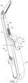
- the operating handle 220 is arranged on the handheld body 210 of the handheld structure 200.
- the operating handle 200 is arranged at only one end of the handheld body 210 with its extension direction consistent with that of the handheld body 210, its projection towards the handheld body 210 being within the handheld body 210, an end of the handheld structure 200 opposite the operating handle 220 being the inserting end 211.
- various parts of the handheld structure 200 can be arranged in the same direction, resulting in an overall styling that is smooth, aesthetic, simple, and compact.
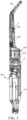
- the device body 100 can comprise a first mounting part 170 and a handheld part 130 removably connected to the first mounting part 170.
- the handheld part 130 is configured to be held by a user to facilitate control of the device body 100's position.
- partial structures of the handheld part 130 and the first mounting part 170 ca be configured together as groove-shaped structures, forming the positioning groove 110 and the supporting groove 120 that match the handheld structure 200.
- the positioning groove 110 is arranged at a side face of the device body 100 and comprises a receiving section 111 and an abutting section 112 in communication with each other. The abutting section 112 is located above the receiving section 111.
- the receiving section 111 and the abutting section 112 support the handheld structure 200 together, which helps improve the stability of the handheld structure 200 and thus can ensure the structural stability of the cleaning device.
- the supporting groove 120 in communication with the positioning groove 110, when mounting the handheld structure 200, the inserting end 211 can be inserted into the supporting groove 120 and enveloped by the supporting groove 120 so as to limit the inserting end 211's movement.
- a mounting space that opens sideways can be formed by the positioning groove 110 and the supporting groove 120, which facilitates mounting and removal of the handheld structure 200 from one side of the device body 100.
- the mounting space can partially envelope the handheld structure 200 to hide it, resulting in a smooth and sleek exterior styling.
- the partial structure of the handheld structure 200 located outside the mounting space can be configured to transition smoothly to the exterior structure of the positioning groove 110 and the supporting groove 120, so as to render the overall styling of the cleaning device more smooth and aesthetic.
- the inserting end 211 of the handheld body 210 is completely enveloped by the supporting groove 120 of the device body 100, a part of a side face of the handheld body 210 is located in the positioning groove 110, and at least a part of the operating handle 220 is also located in the positioning groove 110.
- the partial structure of the handheld structure 200 exposed outside the positioning groove 110 and the supporting groove 120 can smoothly transition to an outer surface of the supporting groove 120 and an outer surface of the positioning groove 110, enabling the handheld structure 200 to be stably mounted in the device body 100 in a hidden way, so that the cleaning device has a smooth overall styling, a compact structure, and improved aesthetics.
- a cleaning tool such as a brush can be further provided on the first mounting part 170.
- the brush is made to enter into contact with a surface to be cleaned, so that the cleaning device can be used as a dust removal device capable of removing dust from a surface to be cleaned such as a floor.
- a dirty water tank and a clean water tank can be arranged in the first mounting part 170, wherein the clean water tank is configured for distributing water to a cleaning tool such as a brush to clean a surface to be cleaned, so that the cleaning device is used as a floor scrubber and performs cleaning while removing dust from a floor.
- a cleaning tool such as a brush to clean a surface to be cleaned
- the position of a user when using the cleaning device is always at the side towards which the handheld part 130 tilts.
- the handheld structure 200 and the user can both be located at the same side of the device body 100, so as to facilitate a user's performing operations of mounting, removing, and holding the handheld structure 200 from the same side of the handheld part 130 when using the cleaning device, without the need to repeatedly adjusting his or her position, which further facilitates use of the cleaning device and improvement of user experience.
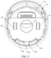
- the cleaning device further comprises a locking assembly 300 comprising a pressing element 310 and a locking element 320.
- the pressing element 310 is inserted in the device body 100.
- the locking element 320 is located in the mounting chamber 140.
- the locking element 320 is partially located outside the mounting chamber 140 and snap-fit with the operating handle 220.
- the pressing element 310 is configured to, when being pressed, drive the locking element 320 to move away from the operating handle 220 so as to disengage the locking element 320 from being snap-fit with the operating handle 220.
- the operating handle 220 is provided with a snap-fit slot 221, and the locking element 320 has a snap-fit tab 321 matching the snap-fit slot 221.
- the snap-fit tab 321 of the locking element 320 will partially extend into the positioning groove 110 via the second mounting hole 142 and be snap-fit with the operating handle 220.
- the handheld structure 200 and the device body 100 are fixed together reliably, which increases the reliability of the connection between the handheld structure 200 and the device body 100 and improves user experience.
- the pressing element 310 can be provided with an insertion block 311, and a face of the locking element 320 facing the insertion block 311 can be provided with an insertion slot 322.
- An end face of the insertion block 311 facing the insertion slot 322 has a second slope 3111 that matches the first slope 3221.
- the first slope 3221 is slidably connected to the second slope 3111.
- the locking assembly 300 further comprises a reset element 330 located in the mounting chamber 140. Specifically, the reset element 330 abuts between the locking element 320 and an inner wall of the mounting chamber 140 and maintains an extended state.
- the pressing element 310 when the pressing element 310 is pressed, it moves towards the receiving chamber via the first mounting hole 141, and under the interaction of the first slope 3221 of the insertion slot 322 and the second slope 3111 of the insertion block 311, drives the locking element 320 to move away from the positioning groove 110 and return into the receiving chamber, so as to disengage from being snap-fit with the operating handle 220, while at the same time compressing the reset element 330 so that the reset element 330 undergoes elastic deformation.
- the reset element 330 extends to restore its shape and drives the locking element 320 to move in the opposite direction until extending into the positioning groove 110 via the second mounting hole 142 and, when the handheld structure 200 is inserted in the positioning groove 110, being snap-fit with the operating handle 220, while at the same time driving the pressing element 310 to return to position by the interaction between the first slope 3221 and the second slope 3111.
- the reset element 330 can be arranged to be a spring.
- the cleaning device further comprises at least one elastic assembly 400 located in the device body 100 and partially protruding into the positioning groove 110 so as to abut against the operating handle 220.
- the elastic assembly 400 is configured to, when the operating handle 220 disengages from being snap-fit with the device body 100, drive the part of the operating handle 220 in the positioning groove 110 to disengage from the positioning groove 110.
- the elastic assembly 400 located in the device body 100 is configured to cooperate with a user to accomplish mounting and removal of the handheld structure 200.
- the elastic assembly 400 comprises a push pin 410 and an elastic element 420 connected to the push pin 410.
- the elastic element 420 can be a spring element.
- a wall of the positioning groove 110 is provided with a passage hole 411 corresponding to the push pin 410.
- the push pin 410 can protrude into the positioning groove 110 via the passage hole 411 so as to abut against the operating handle 220.
- the operating handle 220 is snap-fit with the locking element 320
- the operating handle 220 pushes the push pin 410 into the device body 100 and drives the elastic element 420 to be compressed.
- the elastic element 420 extends and drives the push pin 410 to extend into the positioning groove 110, pushing the operating handle 220 to detach from the positioning groove 110.
- the push pin 410 can push the operating handle 220 to be exposed at an angle relative to the positioning groove 110 so as to facilitate full holding by a user and render it effortless to remove it from inside the positioning groove 110, resulting in a simple structure and convenient removal.
- the specific position of the elastic assembly 400 in the device body 100 need ensure the movement direction of the elastic assembly 400 is consistent with the direction in which the operating handle 220 detaches from the positioning groove 110.
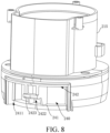
- an end face of the inserting end 211 of the cleaning device provided by the present application has a first electrical connector 2111.
- a bottom of the supporting groove 120 has a second electrical connector 121.
- the first electrical connector 2111 is configured to, when the inserting end 211 is inserted into the supporting groove 120, be electrically connected to the second electrical connector 121.
- the first electrical connector 2111 is a female mating element arranged at the side of an end face of the inserting end 211
- the second electrical connector 121 is a male mating element arranged at the same side as the bottom of the supporting groove 120.
- the female mating element is depressed relative to the end face, and the male mating element protrudes relative to the bottom, insertion connection and positioning of the inserting end 211 can be facilitated, and structural protrusion of the inserting end 211 when the handheld structure 200 is used separately can be reduced, so as to render the overall structure compact and reliable.
- the male and female mating elements can be reversed. This is not limited by the present application.
- an electrical connection between the handheld structure 200 and the device body 100 can be realized by means of the first electrical connector 2111 and the second electrical connector 121.
- electrical control of the handheld structure 200's operating state can be realized by means of an operating panel arranged on the device body 100 when the handheld structure 200 is connected to the device body 100 for use, without the need to control the cleaning device's operation from the handheld structure 200, so that the cleaning device is more flexible and convenient to use.
- one is a positioning slot
- the other is a positioning block that matches the positioning slot.
- not providing the air inlet of the air discharge passage 160 in the end face of the supporting groove 120 means the integrity of the end face of the supporting groove 120 is not damaged too much, which can improve the supporting strength of the end face of the supporting groove 120.
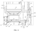
- the cleaning device further comprises a first sealing element 230 arranged between the air admission passage 150 and the air inlet 212, a second sealing element 231 arranged between a side wall of the supporting groove 120 and a side face of the inserting end 211, and a connector 232.
- the first sealing element 230 can be a rubber sealing ring
- the second sealing element 231 can be a rubber sealing stripe.
- the rubber sealing ring is glued to the inserting end 211 in a circumferential direction of the air inlet 212.
- the rubber sealing stripe is glued to a side face of the inserting end 211 in a circumferential direction of the air outlet 213.
- the connector 232 can be two rubber stripes, which can be glued to the inserting end 211.
- one end is connected to the first sealing element 230, and another end is respectively connected to two opposite ends of the second sealing element 231, so that the first sealing element 230, the second sealing element 231, and the connector 232 are formed integrally, which facilitates the mounting and manufacturing of the first sealing element 230, the second sealing element 231, and the connector 232.
- the handheld body 210 comprises a housing 214, a support 215, and a driving element 216 used for providing a suction force.
- the support 215 is partially inserted into the housing 214.
- the support 215 has a chamber inside.
- the driving element 216 is arranged in the chamber. At least part of the support 215 and the housing 214 adjacent to the support 215 form the inserting end 211.
- a part of the chamber forms the air passage.
- An end face of the support 215 facing an end face of the device body 100 forms the end face of the inserting end 211.
- the air inlet 212 corresponds to a suction opening of the driving element 216.
- the air outlet 213 is located in a side face of the support 215.
- a side face of the support 215 has a slot 240.
- An opening of the slot 240 faces a side wall of the supporting groove 120 and forms the air outlet 213.
- the slot 240 has a first side wall 241 and a second side wall 242 that are opposite to each other.
- the first side wall 241 faces the handheld body 210.
- the second side wall 242 is provided with at least one through hole that puts the air passage and the slot 240 in communication.
- the second side wall 242 is provided with two first through holes 2421 that put the air passage and the slot 240 in communication. Air is blown out of the air outlet 213 via the first through holes 2421.
- the opening of the slot 240 faces a side wall of the supporting groove 120.
- a snap-fit part 2423 is arranged in the slot 240.
- a face of the snap-fit part 2423 facing the notch 2411 is provided with a second through hole 2422, which also puts the air passage and the slot 240 in communication, so as to increase the air flow surface of the slot 240, increasing air flow.
- the opening by causing the opening to be inclined by means of the notch 2411, the direction of air blown out of the air outlet 213 is inclined axially outwards relative to the handheld body 210, which reduces wind resistance while at the same time fully making use of the structure's space, and is equivalent to blowing towards the air discharge passage 160 at an angle.
- the cleaning device further comprises an outer connection structure (not illustrated) configured to, when the handheld structure 200 detaches from the device body 100, be connected to the handheld structure 200 and form, together with the handheld structure 200, a cleaning executing device.
- an outer connection structure (not illustrated) configured to, when the handheld structure 200 detaches from the device body 100, be connected to the handheld structure 200 and form, together with the handheld structure 200, a cleaning executing device.
- the outer connection structure to connect with the separate handheld structure 200 to form a cleaning executing device, the functions of the handheld structure 200 can be completed when using the handheld structure 200 separately, so as to improve user experience when separately using the handheld structure 200.
- the outer connection structure is configured to, when the handheld structure 200 detaches from the device body 100, be connected to the handheld structure 200, and form, together with the handheld structure 200, a cleaning executing device.
- the handheld structure 200 When the handheld structure 200 is used separately, it is connected to the outer connection structure and forms a cleaning executing device, which puts it to multiple uses, increases the utilization scenarios of the handheld structure 200, and improves the handheld structure 200's functionality and applicability.
- the outer connection structure is a dust cup structure.
- the dust cup structure is snap-fit with the snap-fit part 2423.
- the dust cup structure is a relevant technology in the art. Its structure is not limited here. Removable connection between the dust cup structure and the handheld structure 200 is achieved by means of the snap-fit part 2423, which facilitates utilization.
- the dust cup structure can be used to receive dust and dirt sucked in by the handheld structure 200, which improves the handheld structure 200's cleaning efficiency and optimizes a user's utilization experience.
- the inserting end 211 of the handheld body 210 is completely enveloped by the supporting groove 120 of the device body 100, a part of a side face of the handheld body 210 is located in the positioning groove 110, and at least a part of the operating handle 220 is also located in the positioning groove 110.
- the supporting groove 120 can guide the insertion of the inserting end 211 and protect the connection between the inserting end 211 and the device body 100.
- the partial structure of the handheld structure 200 exposed outside the positioning groove 110 and the supporting groove 120 can smoothly transition to an outer surface of the supporting groove 120 and an outer surface of the positioning groove 110, enabling the handheld structure 200 to be stably mounted in the device body 100 in a hidden way, so that the cleaning device has a smooth overall styling, a compact structure, and improved aesthetics.
- the locking assembly 300 and its structure it is further ensured that the handheld structure 200 and the device body 100 are connected stably. And by providing the elastic assembly 400, holding of the handheld structure 200 after being unlocked is facilitated. Moreover, by appropriately arranging the opposite positions of the air inlet 212 and the air outlet 213 of the inserting end 211, the relative position and structure of the air admission passage 150 and the air discharge passage 160 of the device body 100 is changed so as to increase available space in the device body 100, rendering the cleaning device more compact as a whole.
Landscapes
- Brushes (AREA)
Applications Claiming Priority (2)
| Application Number | Priority Date | Filing Date | Title |
|---|---|---|---|
| CN202311844512.1A CN120226957A (zh) | 2023-12-28 | 2023-12-28 | 清洁设备 |
| CN202323628625.6U CN222055329U (zh) | 2023-12-28 | 2023-12-28 | 清洁设备 |
Publications (1)
| Publication Number | Publication Date |
|---|---|
| EP4578353A1 true EP4578353A1 (de) | 2025-07-02 |
Family
ID=92582782
Family Applications (1)
| Application Number | Title | Priority Date | Filing Date |
|---|---|---|---|
| EP24196559.9A Pending EP4578353A1 (de) | 2023-12-28 | 2024-08-27 | Reinigungsvorrichtung |
Country Status (1)
| Country | Link |
|---|---|
| EP (1) | EP4578353A1 (de) |
Citations (3)
| Publication number | Priority date | Publication date | Assignee | Title |
|---|---|---|---|---|
| US20100083459A1 (en) * | 2007-01-19 | 2010-04-08 | Aktiebolaget Electrolux | Air Flow Losses in Vacuum Cleaners |
| US8671510B2 (en) * | 2010-05-31 | 2014-03-18 | Samsung Electronics Co., Ltd. | Hand-held and stick vacuum cleaner |
| US9757001B2 (en) * | 2014-08-21 | 2017-09-12 | Lg Electronics Inc. | Vacuum cleaner |
-
2024
- 2024-08-27 EP EP24196559.9A patent/EP4578353A1/de active Pending
Patent Citations (3)
| Publication number | Priority date | Publication date | Assignee | Title |
|---|---|---|---|---|
| US20100083459A1 (en) * | 2007-01-19 | 2010-04-08 | Aktiebolaget Electrolux | Air Flow Losses in Vacuum Cleaners |
| US8671510B2 (en) * | 2010-05-31 | 2014-03-18 | Samsung Electronics Co., Ltd. | Hand-held and stick vacuum cleaner |
| US9757001B2 (en) * | 2014-08-21 | 2017-09-12 | Lg Electronics Inc. | Vacuum cleaner |
Similar Documents
| Publication | Publication Date | Title |
|---|---|---|
| CN105455725B (zh) | 真空吸尘器 | |
| US6311366B1 (en) | Battery power combination vacuum cleaner | |
| EP0192624B1 (de) | Leichter, batteriebetriebener Staubsauger | |
| US4841594A (en) | Cordless vacuum cleaner with power brush | |
| US5561885A (en) | Portable hand-held vacuum cleaner | |
| KR102321633B1 (ko) | 청소기 및 이를 갖는 청소장치 | |
| CN215227297U (zh) | 清洁基站及清洁装置 | |
| KR100804806B1 (ko) | 진공청소기 | |
| KR100545266B1 (ko) | 진공청소기의 접이식 브러시 | |
| EP4578353A1 (de) | Reinigungsvorrichtung | |
| CN211511623U (zh) | 复合吸尘器 | |
| US20250339004A1 (en) | Cleaner | |
| CN222055329U (zh) | 清洁设备 | |
| KR100640920B1 (ko) | 진공 청소기용 흡입구체 | |
| CN120226957A (zh) | 清洁设备 | |
| CN216020788U (zh) | 一种水箱、清洁地刷及清洁设备 | |
| CN209733839U (zh) | 刷头及吸尘器 | |
| CN217488525U (zh) | 一种清洁设备 | |
| CN221813814U (zh) | 用于清洁设备的吸入清洁模块和清洁设备 | |
| CN222323478U (zh) | 一种吸尘器 | |
| CN216602726U (zh) | 一种清洁地刷及清洁设备 | |
| CN223817477U (zh) | 清洁设备 | |
| CN110974086A (zh) | 复合吸尘器 | |
| CN221285644U (zh) | 排液结构及地刷 | |
| CN220631977U (zh) | 一种清洁器及具有其的清洁基站 |
Legal Events
| Date | Code | Title | Description |
|---|---|---|---|
| PUAI | Public reference made under article 153(3) epc to a published international application that has entered the european phase |
Free format text: ORIGINAL CODE: 0009012 |
|
| STAA | Information on the status of an ep patent application or granted ep patent |
Free format text: STATUS: THE APPLICATION HAS BEEN PUBLISHED |
|
| AK | Designated contracting states |
Kind code of ref document: A1 Designated state(s): AL AT BE BG CH CY CZ DE DK EE ES FI FR GB GR HR HU IE IS IT LI LT LU LV MC ME MK MT NL NO PL PT RO RS SE SI SK SM TR |
|
| STAA | Information on the status of an ep patent application or granted ep patent |
Free format text: STATUS: REQUEST FOR EXAMINATION WAS MADE |
|
| 17P | Request for examination filed |
Effective date: 20250827 |
|
| RAP3 | Party data changed (applicant data changed or rights of an application transferred) |
Owner name: ZHEJIANG SHAOXING SUPORDOMESTIC ELECTRICAL APPLIANCE CO., LTD. |
|
| GRAP | Despatch of communication of intention to grant a patent |
Free format text: ORIGINAL CODE: EPIDOSNIGR1 |
|
| STAA | Information on the status of an ep patent application or granted ep patent |
Free format text: STATUS: GRANT OF PATENT IS INTENDED |
|
| INTG | Intention to grant announced |
Effective date: 20260227 |