EP4578406A2 - System und verfahren zur bestimmung struktureller eigenschaften eines objekts - Google Patents
System und verfahren zur bestimmung struktureller eigenschaften eines objekts Download PDFInfo
- Publication number
- EP4578406A2 EP4578406A2 EP25177006.1A EP25177006A EP4578406A2 EP 4578406 A2 EP4578406 A2 EP 4578406A2 EP 25177006 A EP25177006 A EP 25177006A EP 4578406 A2 EP4578406 A2 EP 4578406A2
- Authority
- EP
- European Patent Office
- Prior art keywords
- force
- contact
- sleeve
- energy application
- application tool
- Prior art date
- Legal status (The legal status is an assumption and is not a legal conclusion. Google has not performed a legal analysis and makes no representation as to the accuracy of the status listed.)
- Pending
Links
Images


Classifications
-
- A—HUMAN NECESSITIES
- A61—MEDICAL OR VETERINARY SCIENCE; HYGIENE
- A61B—DIAGNOSIS; SURGERY; IDENTIFICATION
- A61B5/00—Measuring for diagnostic purposes; Identification of persons
- A61B5/06—Devices, other than using radiation, for detecting or locating foreign bodies ; Determining position of diagnostic devices within or on the body of the patient
- A61B5/065—Determining position of the probe employing exclusively positioning means located on or in the probe, e.g. using position sensors arranged on the probe
-
- A—HUMAN NECESSITIES
- A61—MEDICAL OR VETERINARY SCIENCE; HYGIENE
- A61B—DIAGNOSIS; SURGERY; IDENTIFICATION
- A61B5/00—Measuring for diagnostic purposes; Identification of persons
- A61B5/45—For evaluating or diagnosing the musculoskeletal system or teeth
- A61B5/4533—Ligaments
-
- A—HUMAN NECESSITIES
- A61—MEDICAL OR VETERINARY SCIENCE; HYGIENE
- A61B—DIAGNOSIS; SURGERY; IDENTIFICATION
- A61B5/00—Measuring for diagnostic purposes; Identification of persons
- A61B5/45—For evaluating or diagnosing the musculoskeletal system or teeth
- A61B5/4538—Evaluating a particular part of the muscoloskeletal system or a particular medical condition
- A61B5/4542—Evaluating the mouth, e.g. the jaw
- A61B5/4547—Evaluating teeth
-
- A—HUMAN NECESSITIES
- A61—MEDICAL OR VETERINARY SCIENCE; HYGIENE
- A61B—DIAGNOSIS; SURGERY; IDENTIFICATION
- A61B50/00—Containers, covers, furniture or holders specially adapted for surgical or diagnostic appliances or instruments, e.g. sterile covers
-
- A—HUMAN NECESSITIES
- A61—MEDICAL OR VETERINARY SCIENCE; HYGIENE
- A61C—DENTISTRY; APPARATUS OR METHODS FOR ORAL OR DENTAL HYGIENE
- A61C17/00—Devices for cleaning, polishing, rinsing or drying teeth, teeth cavities or prostheses; Saliva removers; Dental appliances for receiving spittle
- A61C17/16—Power-driven cleaning or polishing devices
- A61C17/22—Power-driven cleaning or polishing devices with brushes, cushions, cups, or the like
- A61C17/224—Electrical recharging arrangements
-
- A—HUMAN NECESSITIES
- A61—MEDICAL OR VETERINARY SCIENCE; HYGIENE
- A61C—DENTISTRY; APPARATUS OR METHODS FOR ORAL OR DENTAL HYGIENE
- A61C19/00—Dental auxiliary appliances
- A61C19/04—Measuring instruments specially adapted for dentistry
-
- G—PHYSICS
- G01—MEASURING; TESTING
- G01M—TESTING STATIC OR DYNAMIC BALANCE OF MACHINES OR STRUCTURES; TESTING OF STRUCTURES OR APPARATUS, NOT OTHERWISE PROVIDED FOR
- G01M7/00—Vibration-testing of structures; Shock-testing of structures
- G01M7/08—Shock-testing
-
- G—PHYSICS
- G01—MEASURING; TESTING
- G01N—INVESTIGATING OR ANALYSING MATERIALS BY DETERMINING THEIR CHEMICAL OR PHYSICAL PROPERTIES
- G01N3/00—Investigating strength properties of solid materials by application of mechanical stress
- G01N3/30—Investigating strength properties of solid materials by application of mechanical stress by applying a single impulsive force, e.g. by falling weight
-
- G—PHYSICS
- G06—COMPUTING OR CALCULATING; COUNTING
- G06F—ELECTRIC DIGITAL DATA PROCESSING
- G06F1/00—Details not covered by groups G06F3/00 - G06F13/00 and G06F21/00
- G06F1/26—Power supply means, e.g. regulation thereof
- G06F1/32—Means for saving power
- G06F1/3203—Power management, i.e. event-based initiation of a power-saving mode
-
- A—HUMAN NECESSITIES
- A61—MEDICAL OR VETERINARY SCIENCE; HYGIENE
- A61B—DIAGNOSIS; SURGERY; IDENTIFICATION
- A61B50/00—Containers, covers, furniture or holders specially adapted for surgical or diagnostic appliances or instruments, e.g. sterile covers
- A61B2050/005—Containers, covers, furniture or holders specially adapted for surgical or diagnostic appliances or instruments, e.g. sterile covers with a lid or cover
-
- A—HUMAN NECESSITIES
- A61—MEDICAL OR VETERINARY SCIENCE; HYGIENE
- A61B—DIAGNOSIS; SURGERY; IDENTIFICATION
- A61B90/00—Instruments, implements or accessories specially adapted for surgery or diagnosis and not covered by any of the groups A61B1/00 - A61B50/00, e.g. for luxation treatment or for protecting wound edges
- A61B90/06—Measuring instruments not otherwise provided for
- A61B2090/064—Measuring instruments not otherwise provided for for measuring force, pressure or mechanical tension
-
- A—HUMAN NECESSITIES
- A61—MEDICAL OR VETERINARY SCIENCE; HYGIENE
- A61B—DIAGNOSIS; SURGERY; IDENTIFICATION
- A61B2560/00—Constructional details of operational features of apparatus; Accessories for medical measuring apparatus
- A61B2560/02—Operational features
- A61B2560/0266—Operational features for monitoring or limiting apparatus function
- A61B2560/028—Arrangements to prevent overuse, e.g. by counting the number of uses
- A61B2560/0285—Apparatus for single use
-
- A—HUMAN NECESSITIES
- A61—MEDICAL OR VETERINARY SCIENCE; HYGIENE
- A61B—DIAGNOSIS; SURGERY; IDENTIFICATION
- A61B2560/00—Constructional details of operational features of apparatus; Accessories for medical measuring apparatus
- A61B2560/04—Constructional details of apparatus
- A61B2560/0406—Constructional details of apparatus specially shaped apparatus housings
- A61B2560/0418—Pen-shaped housings
-
- A—HUMAN NECESSITIES
- A61—MEDICAL OR VETERINARY SCIENCE; HYGIENE
- A61B—DIAGNOSIS; SURGERY; IDENTIFICATION
- A61B2560/00—Constructional details of operational features of apparatus; Accessories for medical measuring apparatus
- A61B2560/04—Constructional details of apparatus
- A61B2560/0406—Constructional details of apparatus specially shaped apparatus housings
- A61B2560/0425—Ergonomically shaped housings
-
- A—HUMAN NECESSITIES
- A61—MEDICAL OR VETERINARY SCIENCE; HYGIENE
- A61B—DIAGNOSIS; SURGERY; IDENTIFICATION
- A61B2562/00—Details of sensors; Constructional details of sensor housings or probes; Accessories for sensors
- A61B2562/02—Details of sensors specially adapted for in-vivo measurements
- A61B2562/0233—Special features of optical sensors or probes classified in A61B5/00
-
- A—HUMAN NECESSITIES
- A61—MEDICAL OR VETERINARY SCIENCE; HYGIENE
- A61B—DIAGNOSIS; SURGERY; IDENTIFICATION
- A61B2562/00—Details of sensors; Constructional details of sensor housings or probes; Accessories for sensors
- A61B2562/02—Details of sensors specially adapted for in-vivo measurements
- A61B2562/0247—Pressure sensors
-
- A—HUMAN NECESSITIES
- A61—MEDICAL OR VETERINARY SCIENCE; HYGIENE
- A61B—DIAGNOSIS; SURGERY; IDENTIFICATION
- A61B5/00—Measuring for diagnostic purposes; Identification of persons
- A61B5/0048—Detecting, measuring or recording by applying mechanical forces or stimuli
- A61B5/0051—Detecting, measuring or recording by applying mechanical forces or stimuli by applying vibrations
-
- A—HUMAN NECESSITIES
- A61—MEDICAL OR VETERINARY SCIENCE; HYGIENE
- A61B—DIAGNOSIS; SURGERY; IDENTIFICATION
- A61B5/00—Measuring for diagnostic purposes; Identification of persons
- A61B5/0048—Detecting, measuring or recording by applying mechanical forces or stimuli
- A61B5/0057—Detecting, measuring or recording by applying mechanical forces or stimuli by applying motion other than vibrations, e.g. rolling, rubbing, applying a torque, tribometry
-
- A—HUMAN NECESSITIES
- A61—MEDICAL OR VETERINARY SCIENCE; HYGIENE
- A61B—DIAGNOSIS; SURGERY; IDENTIFICATION
- A61B5/00—Measuring for diagnostic purposes; Identification of persons
- A61B5/103—Measuring devices for testing the shape, pattern, colour, size or movement of the body or parts thereof, for diagnostic purposes
- A61B5/11—Measuring movement of the entire body or parts thereof, e.g. head or hand tremor or mobility of a limb
- A61B5/1111—Detecting tooth mobility
-
- A—HUMAN NECESSITIES
- A61—MEDICAL OR VETERINARY SCIENCE; HYGIENE
- A61B—DIAGNOSIS; SURGERY; IDENTIFICATION
- A61B5/00—Measuring for diagnostic purposes; Identification of persons
- A61B5/68—Arrangements of detecting, measuring or recording means, e.g. sensors, in relation to patient
- A61B5/6801—Arrangements of detecting, measuring or recording means, e.g. sensors, in relation to patient specially adapted to be attached to or worn on the body surface
- A61B5/6843—Monitoring or controlling sensor contact pressure
-
- A—HUMAN NECESSITIES
- A61—MEDICAL OR VETERINARY SCIENCE; HYGIENE
- A61B—DIAGNOSIS; SURGERY; IDENTIFICATION
- A61B9/00—Instruments for examination by percussion; Pleximeters
-
- A—HUMAN NECESSITIES
- A61—MEDICAL OR VETERINARY SCIENCE; HYGIENE
- A61B—DIAGNOSIS; SURGERY; IDENTIFICATION
- A61B90/00—Instruments, implements or accessories specially adapted for surgery or diagnosis and not covered by any of the groups A61B1/00 - A61B50/00, e.g. for luxation treatment or for protecting wound edges
- A61B90/06—Measuring instruments not otherwise provided for
-
- G—PHYSICS
- G01—MEASURING; TESTING
- G01N—INVESTIGATING OR ANALYSING MATERIALS BY DETERMINING THEIR CHEMICAL OR PHYSICAL PROPERTIES
- G01N2203/00—Investigating strength properties of solid materials by application of mechanical stress
- G01N2203/0058—Kind of property studied
- G01N2203/0076—Hardness, compressibility or resistance to crushing
- G01N2203/0083—Rebound strike or reflected energy
-
- G—PHYSICS
- G01—MEASURING; TESTING
- G01N—INVESTIGATING OR ANALYSING MATERIALS BY DETERMINING THEIR CHEMICAL OR PHYSICAL PROPERTIES
- G01N2203/00—Investigating strength properties of solid materials by application of mechanical stress
- G01N2203/02—Details not specific for a particular testing method
- G01N2203/06—Indicating or recording means; Sensing means
- G01N2203/067—Parameter measured for estimating the property
- G01N2203/0676—Force, weight, load, energy, speed or acceleration
Definitions
- the sensor for example the force sensor, may be in physical proximity and/or contact and/or coupled with at least a portion of the device other than the energy application tool, for example, it may be in physical proximity and/or contact and/or coupled with the housing and/or sleeve portion, if the open end of the sleeve portion includes an object contacting portion, as noted above.
- the sensor may include at least one strain gauge for sensing.
- the strain gauges may be attached or mounted to a cantilever between the device housing and the sleeve portion so that when the object contacting portion of the sleeve portion is pressed on the object it also deforms the cantilever which is measured by the strain gauge, thus providing a force measurement.
- strain gauges mounted to a single or to separate cantilevers may be utilized.
- the cantilever(s) may also, for example, be present on a separate component from the rest of the housing or sleeve portion, such as, for example, on a mounting device.
- the sensor may include a sensing pad which may be positioned between a rigid surface and a sliding part so that when the pad is pressed or squeezed as the sliding part moves towards the rigid surface, the force is measured.
- the rigid surface may be, for example, a coil interface that holds the electromagnetic coil in the drive mechanism within the device housing.
- the sliding part may be a force transfer sleeve like component disposed inside the housing and coupled to the object contacting portion of the sleeve portion and adapted to slide inside the housing when a force is exerted by the object contacting portion of the sleeve portion on an object. In some embodiments, it may be disposed inside the sleeve portion.
- the sliding distance may be very small, for example, in the order of about (in millimeters or mm) .3mm to about 1mm, more for example about .5mm.
- the sensing pad may include a layer structure, which may be generally referred to as a "Shunt Mode FSR (force sensing resistor) that may change resistance depending on the force applied to the pad, to provide a force measurement.
- the force transfer sleeve like component may be biased forward by a spring, so that when force is applied by the object contacting portion of the sleeve portion on the object, the force transfer sleeve like portion may transfer the force against the spring.
- the force sensing may be done by a linear position sensor, which would know, for example, that if the force transfer sleeve like portion is at position X, a force of Y has to be applied to it (against the reaction force of the spring) to move it to that position.
- the force sensing may be performed by an optical sensor, for optically sensing the position of the moving part, when it is pushed against a spring
- the relative position of the object contacting portion of the sleeve portion on the object may be determined by having one or more strain gauges which may be attached at one end to a moving part, for example, the force sensor sleeve like component, and the other end to a static element, for example, the housing.
- the device may include piezoelectric elements for directly measuring the force.
- a hall effect sensor may be used to detect a change in the magnetic field when a magnet (attached to the moving element) is moving relative to the position of the sensor.
- a capacitive linear encoder system like that found in digital calipers may be used to measure the force.
- the senor is not physically or mechanically coupled to the energy application tool, it may be in electronic communication with the energy application tool and may act as an on/off switch for the device or instrument, as noted above.
- the sensor may act as an on/off switch for the device or instrument, as noted above.
- a proper force is exerted on the object by the object contacting portion of the sleeve, it may trigger the activation mechanism of the device or instrument to activate the movement of the energy application tool to start a measurement.
- no external switches or push buttons are needed to activate the on and off of the system, as noted above.
- the indication of the proper force may be indicated by visible or audible signals.
- the instrument may be instantaneously turned on once a proper contact force is exerted by the object contacting portion of the sleeve on the object, as indicated by visible or audible signals. In another embodiment, there may be a delay prior to turning on the instrument once a proper contact force is exerted by the object contacting portion of the sleeve on the object, as indicated by visible or audible signals. In a further embodiment, once a certain push force between the object contacting portion of the sleeve portion and the object is detected and maintained for a period of time, for example, about 1 second, more for example, about 0.5 seconds, the instrument may be turned on to start measurement. In this embodiment, a green light lights up the tip, and percussion will begin approximately 1 second, more for example, 0.5sec after a force in the correct range is maintained.
- the proper force exerted by the operator on the object acts as a switch of the system.
- the force measurement may be connected to a visual output, such as lights.
- Lights may be mounted at any convenient location on the device or instrument, for example, one or multiple LEDs may be mounted at the front of the device or instrument. In one aspect, a multiple light system may be included. For example, two LEDs may be used. When the force is in the correct range, the green light may be lit. If too much force is detected, the LEDs may change to red, and the instrument will not work unless the push force is reduced.
- the light may change first to amber, then to red. If the push force is sufficient to change the light to red, percussion may either not be started, or be interrupted if it has already started. In addition, there may be an amber LED state which warns when the user is approaching too much push force. At that stage, the instrument may still operate when the LEDs are lit amber.
- no light may indicate too little force
- a green light may indicate the right amount of force
- a red light may indicate too much force.
- a one light system may be included. For example, no light may give a signal of too little force and a red light may give a signal of too much force.
- a flashing red light may indicate too much force and no light may indicate too little force.
- the force measurement may be connected to an audible output.
- the audible output may include a beeping sound to indicate too little force and a multiple beep to indicate too much force.
- the audible output may include a beeping sound to indicate too little force and a beeping sound with a flashing red light to indicate too much force.
- the force measurement may be connected to a voice alert system for alerting too much force or too little force.
- the force measurement may be connected to a voice alert system to alert too little force and a voice alert and a flashing red light for alerting too much force.
- the force sensor When the force sensor acts as an on/off switch, it may also act to monitor that a proper force is exerted by the object contacting portion of the sleeve portion during measurement and/or a proper alignment of the object contacting portion of the sleeve portion against the object during measurement is obtained.
- An inclinometer may be present, for example, as part of an electronic control system, which may trigger an audible warning when the device is outside of the angular range of operation, for example, for a tapping rod, it may trigger the warning when it is plus/minus approximately 45 degrees, more for example, 30 degrees from horizontal.
- the device is oriented such that the axis of operation is greater than about 45 degrees, more for example, greater than about 30 degrees from horizontal when a push force is sensed on the object contacting portion of the sleeve portion, it may result in a warning sound being emitted by a speaker located on the device, such as the printed circuit board (PCB) within the device. In such circumstances, the percussion action will not begin until the device is returned to an acceptable angle. In some instances, if the percussion action has started when the above-mentioned departure from the range is detected, the device may not actually stop operation, but may simply be sounding an alarm, so that corrections may be made.
- PCB printed circuit board
- the energy application tool has a length with a resting configuration and an active configuration.
- the movement may be axial movement along the longitudinal axis of the housing, or for oscillatory movement about the longitudinal axis of the housing.
- the resting configuration may be a retracted form and the active configuration may be an extended form when the energy application tool moves axially along the longitudinal axis of the housing, and the retracted form being retracted from the extended form.
- the movement of the energy application tool for example, a tapping rod, may be effected by a drive mechanism mounted inside the housing for driving it axially within the housing between a retracted position and an extended position during operation.
- the free end of the energy tool may extend or protrude from the open end of the housing or sleeve portion, if one is present, and substantially extended to contact the object undergoing measurement.
- the instrument may be of any size including a size that enables measurements be undertaken at locations which are relatively inaccessible such as, for example, in the molar area of a patient's teeth.
- the movement of the energy application tool for example, a tapping rod
- a drive mechanism mounted inside the housing for driving the tapping rod from a substantially parallel position to the longitudinal axis of the housing to a position making an acute angle with the axis at a pivot point and back again, while the tip oscillates up and down in turn.
- measurements may be undertaken at locations which are relatively inaccessible such as, for example, in the molar area of a patient's teeth.
- the sleeve portion may attach and/or surround at least a length of the free end of the housing and protrudes from the housing for a distance substantially coextensive with the end of the energy application tool, for example, the tapping rod in its extended form if the tapping rod moves axially.
- the length of the sleeve portion in this embodiment may be somewhat dependent on the length of protrusion of the extended tapping rod desired.
- the free end of the sleeve may be placed against an object undergoing measurement. The contact by the sleeve portion on the object helps to stabilize the device on the object, as noted above.
- the sleeve portion may be attached to the end of the housing and being substantially perpendicular to it when the energy application tool, for example, the tapping rod moves from being substantially parallel to making an acute angle with the longitudinal axis of the housing at a pivot when in operation.
- the sleeve portion may be substantially cylindrical in shape.
- the sleeve may be an extension of the housing and being of substantially a half cylindrical shape to allow the energy application tool, for example, the tapping rod to freely move when the tapping rod moves from being substantially parallel to making an acute angle with the longitudinal axis of the housing in operation.
- measurements may be undertaken at locations which are relatively inaccessible such as, for example, in the molar area of a patient's teeth.
- the system described above may also include disposable features for aiding in eliminating or minimizing contamination of the object undergoing the measurement through transfer from the system or cross-contamination from previous objects undergoing the measurements, without interfering with the measurement or the capability of the system.
- the disposable feature may include any of those described below or as disclosed in U.S. publication no. 20130174639 , entitled “System and Method For Determining Structural Characteristics Of An Object", the contents of which is hereby incorporated by reference in its entirety.
- the present invention also relates to a system and method for measuring structural characteristics using an energy application tool and includes disposable features for aiding in eliminating or minimizing contamination of the object undergoing the measurement through transfer from the system or cross-contamination from previous objects undergoing the measurements, without interfering with the measurement or the capability of the system.
- the instrument includes a housing having a hollow interior with an open end and an energy application tool, for example, a tapping rod, or impact rod mounted inside the housing for movement inside the housing.
- the system provides a non-destructive method of measurement with some contact with the object undergoing such measurement without the need for wiping or autoclaving of the energy application tool, and at the same time without disposing of the energy application tool and/or the housing and whatever may be housed inside the housing of the instrument.
- the housing has a longitudinal axis and the energy application tool has a length with a resting configuration and an active configuration.
- the housing includes a sleeve portion extending therefrom.
- the sleeve portion is open at its free end, and has an object resting or contacting portion for resting on, pressing or contacting an object just prior and during measurement.
- the energy application tool is driven by a drive mechanism.
- the drive mechanism may be an electromagnetic mechanism, and may include an electromagnetic coil and a permanent magnet secured to the back end of the energy application tool, for example, the tapping rod.
- the electromagnetic coil may lie axially behind the permanent magnet, for example.
- the resting configuration may be a retracted form and the active configuration may be an extended form and the energy application tool moves axially along the longitudinal axis of the housing, with the retracted form being retracted from the extended form.
- the movement of the energy application tool for example, a tapping rod, may be effected by a drive mechanism mounted inside the housing for driving it axially within the housing between a retracted position and an extended position during operation.
- the free end of the energy tool may extend or protrude from the open end of the housing or sleeve portion, if one is present, and substantially extended to contact the object undergoing measurement.
- the instrument may be of any size including a size that enables measurements be undertaken at locations which are relatively inaccessible such as, for example, in the molar area of a patient's teeth.
- the resting configuration of the energy application tool may be a form that is substantially parallel to the longitudinal axis of the housing, and the active configuration may be a form making an acute angle with the longitudinal axis of the housing.
- the energy application tool oscillates from the substantially parallel position to the longitudinal axis of the housing to a position making an acute angle with the longitudinal axis of the housing about a pivot point.
- the energy application tool may be held either horizontally or in other positions during measurement, and may have a tip portion that is substantially perpendicular to the major portion of the tool and maintains a constant length either at rest or at impact.
- the movement of the energy application tool may be effected by a drive mechanism mounted inside the housing for driving the tapping rod from a substantially parallel position to the longitudinal axis of the housing to a position making an acute angle with the axis at a pivot point and back again, while the tip oscillates up and down in turn.
- measurements may be undertaken at locations which are relatively inaccessible such as, for example, in the molar area of a patient's teeth.
- the disposable feature may include a covering for enveloping a part of the system that may come into proximity or contact with the object undergoing the measurement without interfering with the sensitivity, reproducibility, if desired, or general operation of the instrument to any substantial degree.
- the covering may include a sleeve portion extending from and/or enveloping the open end of the housing.
- the sleeve portion includes a hollow interior and an open free end with an object resting or contacting portion for resting on, pressing or contacting an object during measurement at its open end.
- a feature such as a contact feature having a length and disposed towards the open end of the sleeve portion, fits snuggly inside the sleeve portion, for example, by friction.
- the contact feature may be, for example, a short tubular section, or a ring, and is adapted for freely moving or sliding inside the sleeve portion, substantially along the longitudinal axis of the sleeve portion, and may include a closed end for substantially closing the off the free end of the sleeve portion.
- the contact feature may be positioned in between the tip of the energy application tool and the surface of the object undergoing measurement and by being freely moving or sliding, may adjust itself to various surface configurations of an object undergoing measurement.
- the freely moving or sliding contact feature may vary in size and/or otherwise be adapted to move a desired predetermined distance along the longitudinal axis of the sleeve portion.
- movement stops such as small ridges, stops or other obstacles, may be present inside the sleeve portion to prevent sliding or movement inside the sleeve portion outside of a desired range.
- at least a portion of the closed end may be in the proximity of the surface of the object, and may or may not be in contact with the surface of the object just prior to impact by the energy application tool on the contact feature.
- at least a portion of the outside surface of the closed end or object contacting surface of the closed end of the contact feature is in close contact with the surface of the object.
- the closed end of the contact feature may include at least a portion that may have a substantially flat portion facing the object to substantially mirror a flat surface of an object.
- the closed end of the contact feature may include at least a portion that may be contoured to mirror the surface of an object it comes into contact with if the object surface is contoured.
- the back part of the housing if the device is a handpiece, and any electrical supply lines, the electromagnetic coil form a structural unit which may be integrally operational and which may be connected to the remaining device permanently.
- the energy application tool such as the tapping rod, is located in the front part of the housing and the mounting mechanism for the tapping rod may include frictionless bearings. These bearings may include one or more axial openings so that the neighboring chambers formed by the housing and the tapping rod are in communication with one another for the exchange of air.
- the drive mechanism may include a measuring device, for example, a piezoelectric force sensor, located within the housing for coupling with the energy application tool, such as the tapping rod.
- the measuring device is adapted for measuring the deceleration of the tapping rod upon impact with an object during operation, or any vibration caused by the tapping rod on the specimen.
- the piezoelectric force sensor may detect changes in the properties of the object and may quantify objectively its internal characteristics. Data transmitted by the piezoelectric force sensor may be processed by a system program, to be discussed further below.
- changes in the structure of the tooth that reduce its ability to dissipate the mechanical energy associated with an impact force, and thus reduce overall tooth structural stability, can be detected by evaluation of the energy return data as compared to an ideal non-damaged sample.
- the present invention also contributes to the accuracy of the location of detection of defects, cracks, micro-cracks, fractures, microfracture, leakage, lesions, loss of cement seal; microleakage; decay; structural integrity in cement failure; bond failure; general or structural stability in general.
- each device may be accompanied by its own charging base station. This may avoid the possibility of the wrong device communicating with the wrong base station, in a multiple device environment. This may be important in any testing setting, for example, a dental office.
- the device During preparation of the system just prior to performing a measurement on an object, the device is docked in the charging base to pair that device with that base station as part of the usage protocol, for example, prior to starting a patient testing session in a dental office.
- the usage protocol may be controlled by the software.
- the disposable portion is generally removed from the device prior to placing the device in the charging base. In other embodiments, the disposable portion may be physically accommodated in the interface between the device and the base.
- the present invention yet further relates to a non-reusable and disposable assembly or feature in a healthcare setting.
- the disposable feature or assembly is for aiding in eliminating or minimizing contamination of the object undergoing the measurement through transfer from the system or cross-contamination from previous objects undergoing the measurements, without having to carry out a decontaminating process prior to moving to a different test object.
- the disposable features or assemblies may be programmed to be one use.
- a computer chip may be used. The chip may be present on a PCB located on the disposable feature or assembly, for example, in the back of the disposable assembly, may serves to ensure that once used, it cannot be or is not reused, so that any unwanted material may not be transferred from one patient to another.
- the chip in the assembly or feature is interrogated by the device with a challenge and response system to ensure authenticity. Once authenticated, it is permanently marked as 'used'. If a used assembly or feature is placed on the device again, whether it is the same device or a different one, the challenge and response will fail, and the device will not be able to function as intended.
- a timeout function may also be used to prevent the reuse of the disposable assembly or feature after a certain period of coupled time.
- the chip as well as the timeout function may be used for further insurance.
- the attachment mechanism of the disposable feature or assembly may include a part that once removed from the device is either snapped off or is warp to render it no longer attachable to a device.
- better lighting of the object undergoing measurement may be provided, such as with light pipes or other illumination which may be used to enable better lighting of the object and enhance the visualization by the user.
- the light pipes may also be utilized to aid in coupling between components, such as between the handpiece and the disposable feature.
- the present invention may be used to test objects of practically any size and shape, to obtain information on their structural characteristics.
- the measuring device may come in any sizes also, for example, it may be a handpiece useful for testing objects that may be difficult to measure with usual tools.
- the system may be used to conduct non-destructive measurements.
- Such structural characteristics not only include the physical characteristics of an object or the foundation the object may be anchored to, but also information as to their locations, compatibility or suitability of a material for use in dental work prior to the actual work, whether a tooth structure is restorable prior to the actual work, whether a restorative procedure is successful, when the tooth structure that underwent any procedure has been remodeled, the looseness of tooth structure before and after dental work, and combinations thereof.
- the system and method of the present invention is a non-destructive method. This is applicable to a system that may or may not have disposable parts and/or features for aiding in repositionability.
- the device may be part of a system that includes computerized hardware and instrumentation software that may be programmed to activate, input and track the action and response of the device for determining the structural characteristics of the object.
- the hardware may include a computer for controlling the device and for analyzing any data collected, for example, the deceleration of the energy applying tool, for example, the tapping rod, upon impact with an object.
- the device and hardware may communicate via wired connection(s), wireless connection(s) and/or a combination.
- the energy application tool for example, the tapping rod extends at a speed toward an object and the deceleration of the tapping rod upon impact with the object may be measured by a measuring device, for example, a piezoelectric force sensor, installed in the device, and transmitted to the rest of the system for analysis.
- the tapping rod may be programmed to repeatedly strike an object, for example, a certain number of times per second or minute at substantially the same speed and the deceleration information is recorded or compiled for analysis by the system.
- the object may be struck 4 times per second.
- the object may be subjected to an energy application processes provided via a device, for example, a handpiece, which forms a part of a computerized system capable of collecting and analyzing any data animating from the object.
- a device for example, a handpiece, which forms a part of a computerized system capable of collecting and analyzing any data animating from the object.
- many different structural characteristics may be determined using the system and methods of the present invention, including vibration damping capacities, acoustic damping capacities, structural integrity or structural stability of both mechanical and anatomical objects and any foundations they may be anchored thereon, as noted above.
- examples of the structural characteristics as defined herein may include vibration damping capacities, acoustic damping capacities, or structural stabilities and may indicate the health of the object.
- the health of the object may also be correlated to bone densities or a level of osseointegration; structural integrity such as defects or cracks, noted above.
- structural integrity such as defects or cracks
- examples of the structural characteristics as defined herein may include vibration damping capacities, acoustic damping capacities, or structural stabilities and may indicate the health of the structural integrity of the object.
- the present invention provides an effective and repeatable measurement of the structural characteristics of an object, mentioned above and/or below.
- the instrument of the present invention may be used to such purposes and may be useful to predict the suitability of a material prior to construction in addition in for example, an anatomical object, to detection of loss of cement seal; cement failure; bond failure; microleakage; decay and so on after the construction, as mentioned above.
- the present invention is useful in distinguishing between defects inherent in the material making up the structure or object, and cracks or fractures as discussed above due to trauma or wear or repeated loadings. Defects inherent in the bone or material construction of an implant, or a physical structure, for example, may include lesions in the bone, similar defects in the implant construction or polymer, polymer composites or alloys, any type of ceramics, or metallic composites or alloys.
- the system may include an instrument which houses an energy application tool for generating an applied force on an object, such as through physical impact, percussion or repeated tapping impact, and a sensing mechanism for detecting characteristics of the resulting applied force, such as, for example, the deceleration of the energy application tool upon impact, energy back-propagated from the impact, physical deformation of the energy application tool, and/or any other appropriate characteristic or combination thereof.
- an energy application tool for generating an applied force on an object, such as through physical impact, percussion or repeated tapping impact
- a sensing mechanism for detecting characteristics of the resulting applied force, such as, for example, the deceleration of the energy application tool upon impact, energy back-propagated from the impact, physical deformation of the energy application tool, and/or any other appropriate characteristic or combination thereof.
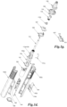
- the instrument may include a handpiece 100 having a housing 102 which houses the energy application tool and sensing mechanism, as illustrated in the block diagram of FIG. 1 and the exploded view of FIGs. 1d .
- a handpiece may refer to a handheld device, but may also include, without limitation, any other appropriate form for the desired application, such as mounted devices or tool/mechanically/robotically articulated devices.
- the handpiece 100 may also be referred to, for example, as a device or instrument interchangeably herein.
- the energy application tool 110 as illustrated, may be mounted within the housing 102 for axial movement in the direction A toward an object, and such axial movement may be accomplished via a drive mechanism 140.
- Drive mechanism 140 may generally be a linear motor or actuator, such as an electromagnetic mechanism which may affect the axial position of the energy application tool 110, such as by producing a magnetic field which interacts with at least a portion of the energy application tool 110 to control its position, velocity and/or acceleration through magnetic interaction.
- an electromagnetic coil disposed at least partially about the energy application 110 may be energized to propel the energy application tool 110 forward toward the object to be measured, as illustrated with the electromagnetic coil 140, which may be retained by a wrapping 140b, as illustrated in the exploded view of FIG. 1e .
- the electromagnetic coil may also, for example, be alternatively energized to propel the energy application tool 110 backward to prepare for a subsequent impact.
- the drive mechanism 140 and/or other portions of the instrument may generally be powered by a power source, as shown with power source 146, which may be a battery, capacitor, solar cell, transducer, connection to an external power source and/or any appropriate combination.
- power source 146 which may be a battery, capacitor, solar cell, transducer, connection to an external power source and/or any appropriate combination.
- An external connection to a power source, either to power the handpiece 100 or to charge the internal power source, such as the power source 146, may be provided, such as a power interface 147 in FIG. 1 , which may include, for example, a power contact 113a as in FIG. 1c and 1d for direct conductive charging, or the power interface 147 may utilize wireless charging, such as inductive charging.
- the energy application tool 110 may be utilized to move substantially in a direction A which may be perpendicular or substantially perpendicular to the longitudinal axis of the housing 102, as illustrated in the block diagram of a handpiece 100 in FIG. 1f .
- the energy application tool 110 may, for example, be substantially L-shaped to accommodate the interaction with the drive mechanism 140 and protrude in direction A, substantially perpendicular to the axis of the housing 102.
- the drive mechanism 140 may act on the energy application tool 110 to cause it to rock on a pivot 110a, causing it to move in direction A at its tip.
- the drive mechanism 140 may utilize, for example, an alternating magnetic element which may act on the energy application tool 110 to cause it to move alternatingly in two directions, such as up and down.
- the bend portion of the L-shaped energy application tool 110 such as shown with bend 110b, may include a flexing and/or deformable construction such that a linear force applied by the drive mechanism 140 may push the energy application tool 110 in the direction A at the tip by conveying the forward motion around bend 110b.
- the bend 110b may include a braided, segmented, spring-like and/or otherwise bendable section that may also convey motion and/or force around a bend.
- a support or bearing may be utilized that the energy application tool 110 may slide freely in, but is constrained from moving off axis, as shown with slide retainer 112b in FIGs. 1d and 1e .
- the handpiece 100 may further house a sensing mechanism 111 for detecting characteristics of the effects from the impact of the energy application tool 110 with the object.
- the sensing mechanism 111 may be physically coupled to, functionally coupled to or otherwise in contact with the energy application tool 110 such that it may detect characteristics of the impact.
- the sensing mechanism 111 may include a piezoelectric sensing element which may generally produce an electrical signal or change in response to mechanical energy, such as a change in pressure on the piezoelectric sensing element, may be utilized for analysis of the object.
- a piezoelectric wire may, for example, be loaded into the energy application tool 110, as shown with the sensing mechanism 111 being inserted in FIG. 1e .
- the sensing mechanism 111 may also include other forms of sensing elements, such as, for example, a linear variable differential transformer which may sense the position of the energy application tool 110 due to changes in voltage in the transformer due to positioning of the energy application tool 110 which may be metal or otherwise affect the induction in the transformer, accelerometers, resistive pressure sensors, strain gauges, and/or any other appropriate type of sensor or combination of sensors.
- the position of the sensing mechanism 111 or portions thereof may be determined for optimal sensing of the desired characteristic.
- a piezoelectric sensing element may generally be placed as close to the point of impact as practicable, such as near the tip that impacts the object, such that a greater amount of physical deformation of the energy application tool 110 may be detected.
- the sensing mechanism 111 may be adapted for measuring the deceleration of the energy application tool 110 upon impact with an object during operation, or any vibration caused by the impact.
- the sensing mechanism 111 may detect changes in the properties of the object and may quantify objectively its internal characteristics. Data transmitted by the sensing mechanism 111 may be processed by a system program, to be discussed further below.
- communication between the drive mechanism 140 or portions of the drive mechanism, for example, the energy application tool 110, the sensing mechanism 111 or the electronics assembly 144 may be via a lead or line of electrically conductive, insulated wire which may be wound spirally in a concentric fashion around the tapping rod and has spring-elastic properties. This may also allow a minimum space requirement with respect to the line management.
- a strand of wires wound concentrically around the energy application tool 110 may be utilized to carry signals to and/or from the sensing mechanism 111.
- One purpose of concentrically winding the wire is to minimize the stress on the wire from repeated forward and back movement of the energy application tool 110.
- a helical spring which may be formed by the spirally wound wire, may help to avoid or prevent looping or twisting of the wire connection.
- the communication between the drive mechanism 140 and the energy application tool 110 may be transmitted wirelessly via any suitable wireless connections.
- the energy application tool 110 such as the tapping rod may be propelled forward by energizing the electromagnetic coil and creating a magnetic field that repels the magnet in the end of the energy application tool, for example, the tapping rod.
- the rod is retracted by reversing the polarity of the voltage applied to the electromagnetic coil.
- the magnet may also serve to hold the rod in its retracted position when the electromagnetic coil is not energized, through its magnetic attraction to the steel core of the coil.
- the handpiece 100 may include features, such as in the electronics assembly 144, which may generally control the drive mechanism 140 and may also store, process and/or transmit data from the sensing mechanism 111.
- the electronics assembly 144 may include, for example, wired or wireless transmission features to relay data to a computer or other device for analysis or viewing.
- the electronics assembly 144 may interface with an outside device, such as via electronics contacts 113 in FIG. 1c , to transmit data.
- the sensing mechanism 111 may connect to the electronics assembly in a wired manner, such as through a wired connection carried in a conduit 111a, which may be flexible, for example, to accommodate the movement of the energy application tool 110.
- the conduit 111a may also provide protection to the wired connection from moving components in the handpiece 100, such as the energy application tool 110.
- FIGs. 5 and 5a illustrate a base station 200 which contains a handpiece receptacle 202 for receiving the handpiece 100.
- the base station 200 may be a separate independent station or it may be part of the system of the present invention.
- any existing station may be applicable.
- the charging mechanism may be wired or wireless.
- For these charging base only electrical current to charge the device may be provided.
- For a base station that may be part of the system more than electrical current to charge the device may be provided.
- the present invention still further relates to a base station that may be part of the system of the present invention and may be plugged into the computer, for example, a PC via a USB cable.
- This connection may provide both data transfer between the PC and the base station, and electrical current to charge the device during the charging process when the device is docked.
- the base station may also serve to act as a wireless transceiver for the PC in the communication with the wireless transceiver in the device.
- the handpiece 100 may include a housing with a hollow interior with an open end, as illustrated in FIGs. 1a, 1b and 1c with housing 102, applicator end 102a with aperture 102c and distal end 102b.
- the energy application tool 110 or at least a portion thereof may emerge from an opening in the housing 102, as shown in FIG. 1c with aperture 102c.
- the housing 102 may also include handling features, such as gripping features 103 as illustrated.
- the housing 102 may also include other features such as to access portions of the interior, such as battery access cover 104.
- the forward end cap 105 may include apertures for portions of the device to emerge, such as the aperture 102c to allow the energy application tool 110 and/or its associated components to emerge.
- FIGs. 1 and 2a illustrate a device coupled to the sleeve 120 which may be utilized to interface with the electronics of the handpiece 100, such as via electronic interface 142, which may utilize contact pins such as electronic contacts 113 in FIG. 1c , or other forms of electronic interface, such as Radio Frequency ID (RFID), Near Field Communication (NFC), Bluetooth, and/or any other appropriate form of interface.
- RFID Radio Frequency ID
- NFC Near Field Communication
- Bluetooth any other appropriate form of interface.
- the sleeve portion may be attached to or at the end of the housing 102 and being substantially perpendicular to it when the energy application tool 110, for example, a tapping rod, moves from being substantially parallel to making an acute angle with the longitudinal axis of the housing 102 at a pivot 110a when in operation.
- the sleeve portion may be substantially cylindrical in shape.
- the sleeve may be an extension of the housing and being of substantially a half cylindrical shape to allow the energy application tool, for example, the tapping rod to freely move when the tapping rod moves from being substantially parallel to making an acute angle with the longitudinal axis of the housing in operation.
- measurements may be undertaken at locations which are relatively inaccessible such as, for example, in the molar area of a patient's teeth.
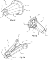
- the contact feature 121 may be a separate component from the rest of the sleeve 120, as illustrated with the contact feature 121 in FIGs. 2b, 2d and 2e .
- a separate contact feature 121 may be desirable, for example, such that it may move at least semi-independently from the rest of the sleeve 120, as discussed further below.
- the separate contact feature 121 may be slidably and/or otherwise translatably disposed in the sleeve 120, as illustrated in the cross-sectional view of FIG. 2b , with the contact tubular portion 121a may rest in the sleeve 120, such as with a semi-frictional fit such that it is partially retained but may still move.
- the contact tubular portion 121a may also include features which may interact with corresponding features of the sleeve 120, such as to provide a limited range of motion, as illustrated with slots 121c and stop tabs 120a.
- the contact feature 121 may be constrained by stops, ridges, bumps or other obstacles to prevent movement beyond a desired range along the longitudinal axis of the sleeve 120, such as illustrated with movement stops 120b, 120c in FIG. 2h .
- the contact feature 121 may include a thin membrane portion which may be of a thickness, deformability and/or shape such that it produces minimal effects on the transmission of forces through it.
- FIG. 2d illustrates an embodiment of a contact feature with a movable contact portion 121a which may include a thin membrane or other layer, as shown with separate contact portion 121b, which may move and/or deform freely, such as a thin plastic film or metal foil.
- the contact feature 121 may be formed with an integral portion which may deform, flex and/or otherwise transmit the forces of the energy application tool 110, such as with a flexible plastic forming the contact feature 121 with a deforming contact portion 121b'.
- the movable contact portion 121a may also be formed to conform to the shape of the energy application tool 110, or vice versa, for optimal transfer of force/energy.
- the movable contact portion 121a may be constructed from metallic foil, for example, stainless steel foil or sheet, and may, for example, be stamped and/or molded, for example, to conform to the end of energy application tool 110, such as with a domed shape.
- metallic foil or sheet such as stainless steel and similar materials may be desirable, for example, due to its high strength characteristics such as rigidity or stiffness, ease of molding/forming, low dampening of transmitted energy or force through it, desirable properties for use in medical or dental applications and/or its commonality or low cost.
- thin stainless steel foil or sheet such as about 0.1mm in thickness, may be utilized.
- the closed end of the contact feature 121 may be integral to the contact feature 121.
- the contact feature 121 may be formed from a material which may be shaped into a tubular or ring structure with a closed end of a desired thickness, such as by stamping a metal (e.g. stainless steel, aluminum, copper, or other appropriate metal).
- a metal e.g. stainless steel, aluminum, copper, or other appropriate metal.
- the contact feature 121 may take the form resembling a thimble or cup, with the closed end being of a thickness to provide deformable or movable characteristics.
- metallic material suitable for the, for example, foil or sheet such as stainless steel and similar metallic material may be austenitic, work hardened, electro-polished, annealed prior to being formed into the desired shape, or superplastically formed into the desired shape.
- the contact feature 121 may be utilized to aid in producing consistent contact of the energy application tool 110 with the surface of an object, such as with surfaces with irregular or inconsistent surface features.
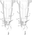
- FIGs. 3 and 3a illustrate the use of the handpiece 100 with an object 90, where the object 90 has non-flat surface features, such as the object 90 with a convex contact surface 95 in FIG. 3 and another object 90 with a concave contact surface 96 in FIG. 3a .
- the object contact surface 123 which rests on the contact surface 94 of the object 90, may sit about an irregular or inconsistent surface feature which may provide a contact point for the energy application tool 110 either ahead or behind the plane of the object contact portion 123, as illustrated with the convex contact surface 95 protruding behind the plane in FIG. 3 and the concave contact surface 96 remaining ahead of the plane in FIG. 3a .
- the contact feature 121 being movable with respect to the object contact surface 123, it may move and/or remain in an unextended or retracted position C, as shown in FIG. 3 , to provide contact with the convex contact surface 95. Further, as shown in FIG.
- the movable contact feature 121 may move to an extended position D to provide contact with the concave contact surface 96.
- the energy application tool 110 may make an initial impact which may push the contact feature 121 to the proper position depending on the shape of the contact surface 94, and may remain substantially in that position or adjust to a different position in subsequent impacts or positionings of the handpiece 100.
- the contact or impact of the energy application tool 110 may be controlled such that it does not cause deformation or damage to the object 90, but rather applies energy through properly accommodated contact as described.
- the sleeve 120 may include a feature for additional stability, such as providing stability substantially perpendicular or orthogonal to the direction A of the energy application tool 110.
- FIGs. 1a, 1b and 2- 2b illustrate sleeve portions with a tab 124 protruding from the sleeve 120 near the object contact portion 123, such that when the object contact portion 123 is in contact with a surface of the object undergoing the measurement, the tab 124 may be resting on a portion of the top of the object, as shown with tab 124 resting on perpendicular surface 92 and object contact portion 123 resting on contact surface 94 of an object 90 in FIGs. 3 and 3a .
- the tab 124 and the object contact portion 123 may thus both assist in the repeatable positioning of the handpiece 100 with respect to the object 90 and the object contact portion 123 may be placed substantially at the same distance from the top of the object at perpendicular surface 92 during subsequent measurements for better reproducibility.
- the object 90 may include an anatomical structure or a physical or industrial structure, though an anatomical structure is shown with a human tooth in FIGs. 3 and 3a .
- the corners of the tab 124 may be smooth or rounded or substantially smooth or rounded to avoid any catching on the object 90 they may be resting on. In other embodiments, the tab 124 may be smooth, though the corners may not necessarily be rounded.
- the sleeve 120 may generally be constructed to withstand multiple sterilization procedures, such as by autoclave, if desired, unless a disposable covering is used, as discussed below.
- the sleeve 120 may be disposable, and if no sleeve is present, along with disposable coverings, if used, and thus may be constructed of any material that may be formed into a sleeve 120. Examples of appropriate materials may include, but are not limited to, for example, a polymer that may be molded, thermoformed or cast.
- any polymeric composite such as engineering prepregs or composites, which are polymers filled with pigments, carbon particles, silica, glass fibers, or mixtures thereof may also be used.
- a blend of polycarbonate and ABS (Acrylonitrile Butadiene Styrene) may be used for the sleeve 120.
- ABS Acrylonitrile Butadiene Styrene
- carbon-fiber and/or glass-fiber reinforced plastic may also be used.
- FIGs. 1 , 1d and 1e illustrate an arrangement where the contact of a portion of the handpiece 100, such as the sleeve portion 120, may push (e.g. through contact at contact points 129 shown in FIGs. 2b and 4 ) on a force transfer member 130, such as a force transfer sleeve or sleeve-like component, which may then exert a force by pushing in direction B on a force sensor 143.
- a force transfer member 130 such as a force transfer sleeve or sleeve-like component
- the force sensor 143 for example, is sandwiched between a relative fixed component, as illustrated with the drive mechanism interface member 141, which itself is rigidly mounted to the drive mechanism 140 as discussed further below, and components that transfer force to the force sensor 143, as shown with the stacking of sleeve 120 (if present), transfer sleeve 112 and the sleeve mount 112a/force transfer member 130, which may pass through the apertures of the portions of the housing, as shown with forward end cap 105 and/or the sleeve mount PCB 108 and its retainer 107.
- a sleeve portion 120 may be mounted onto the force transfer member 130, such as onto sleeve mount 112a which may be coupled to or form a portion of force transfer member 130 and may extend out of the housing 102 via aperture 102a.
- the force from contact with the object may then be transferred, such as illustrated in FIG. 4, 4a and 4b .
- the force transfer member 130 may include separate parts transfer sleeve 112, sleeve mount 112a and force transfer base portion 130b, which may attach or at least contact to provide force transfer, such as at transfer member contacts 130a.
- a biasing member such as the force sensor bias 143a, may further be provided between the force transfer member 130 and the force sensor 143, such as to, for example, distribute the force on the force sensor 143 evenly and/or to serve as a return bias to return the force transfer member 130 to its original position along direction B when the contact with the object ceases, such as via a bias or leaf spring, or elastic cushion.
- the movement such as the sliding distance
- the movement may be very small, for example, in the order of about .3mm to about 1mm, more for example about .5mm.
- the sensor for example the force sensor 143, may be in physical proximity and/or contact and/or coupled with at least a portion of the handpiece 100 other than the energy application tool 110, for example, it may be in physical proximity and/or contact and/or coupled with the sleeve portion 120, if the open end of the sleeve portion 120 may include an object contacting portion 123, as noted above.
- the sensor may include at least one strain gauge for sensing.
- the strain gauges may be attached or mounted to a cantilever between the device housing and the sleeve portion so that when the object contacting portion of the sleeve portion is pressed on the object it also deforms the cantilever which is measured by the strain gauge, thus providing a force measurement.
- a hall effect sensor may be used to detect a change in the magnetic field when a magnet (attached to the moving element) is moving relative to the position of the sensor.
- a capacitive linear encoder system like that found in digital calipers may be used to measure the force.
- the sensing pad may include a layer structure, which may be generally referred to as a "Shunt Mode" FSR (force sensing resistor) that may change resistance depending on the force applied to the pad, to provide a force measurement.
- FSRs typically consist of a conductive polymer, which changes resistance in a predictable manner following application of force to its surface.
- the sensing film of the FSR typically includes both electrically conducting and non-conducting particles suspended in a matrix. Applying a force to the surface of the FSR causes particles to touch the conducting electrodes, changing the resistance of the FSR.
- FSRs may be desirable for their low size, such as with a thickness typically less than 0.5 mm, low cost and good shock resistance.
- Piezoelectric sensors may also be utilized that convert pressure exerted on the force sensor 143 into a change in electrical characteristics, such as a voltage across the piezoelectric element.
- a strain gauge or other similar element may also be included on a leaf spring or other biasing member, such as the force sensor bias 143a.
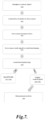
- the contact of the handpiece 100 with the object 90 (300), such as with the sleeve portion 120 may transfer contact force, such as the normal force E from the contact, to the force sensor 143 (301).
- the force sensor 143 may measure the contact force or a transferred force and produce a signal or change in characteristic, such as resistance, voltage, etc. (302).
- the signal or change in characteristic may then be relayed to the control mechanism, such as in the electronics assembly 144 (303).
- the control mechanism may then determine if the contact force is in an acceptable range, for example 5-8 N (304).
- the control mechanism may enable the energy application tool 110 to operate (305) and/or output a signal to the user that the contact force is acceptable (306). If the contact force is out of the acceptable range, the control mechanism may output a signal to the user to change the pressure (307) and/or disable or keep disabled the energy application tool 110 (308). If acceptable, the control mechanism may also initiate the energy application tool 110 automatically and perform a measurement (309). Afterwards, the control mechanism may be reset for a new measurement.
- the proper force exerted by the operator on the object acts as a switch of the system.
- the light may change first to amber, then to red, such as indicated via output from the light sources 114. If the push force is sufficient to change the light to red, percussion may either not be started, or be interrupted if it has already started.
- there may be an amber LED state which warns when the user is approaching too much push force. At that stage, the instrument may still operate when the LEDs are lit amber.
- no light may indicate too little force
- a green light may indicate the right amount of force
- a red light may indicate too much force
- a one light system may be included.
- no light may give a signal of too little force and a red light may give a signal of too much force.
- a flashing red light may indicate too much force and no light may indicate too little force.
- the LEDs may be mounted on the surface of the handpiece 100, or they may be internal to the housing 102 and light may be conveyed via light pipes or fiber optic channels, which may present at the surface of the housing 102, such as at the light sources 114 shown as light pipes in FIG. 1d .
- the light pipes 114 may be integral or attached to a portion of the handpiece 100, such as being integral or attached to the retainer 107' in FIG. 1g , which may be substitute retainer 107 in FIG. 1d .
- the handpiece 100 may also include a reset button, such as shown with reset control 144b in FIG. 1d , such as to reset the handpiece 100 to re-attempt placement with a proper force after an initial incorrect placement.
- the reset button 144b may press onto an appropriate control on the electronics assembly 144 to place the handpiece 100 in a renewed state.
- the instrument may be useful in aiding in the selection of material, such as mechanically biocompatible material, or biomemetically compatible material used in the construction of and/or selection of a material for an anatomical structure, for example, an implant.
- material such as mechanically biocompatible material, or biomemetically compatible material used in the construction of and/or selection of a material for an anatomical structure, for example, an implant.
- the percussive energy generated by mastication is attenuated by the periodontal ligament at the healthy bone-natural tooth interface.
- the ligament is generally lost and the implant may transmit the percussive forces directly into the bone.
- Several materials such as composites, gold, zirconia and so on, used to fabricate the implant abutment have been shown to be effective in numerous studies.
- the instrument of the present invention may be used for such purposes and may be useful to predict the suitability or compatibility prior to implantation, or to choose suitable materials to protect natural teeth adjacent the implants. Thus, the choice of materials may minimize the disparity between the way the implants and natural teeth respond to impact.
- the instrument may be useful in aiding in the selection of material, such as mechanically or chemically durable or compatible material, used in the construction of and/or selection of a material for, for example, a plane, an automobile, a ship, a bridge, a building, any industrial structures including, but limited to power generation facilities, arch structures, or other similar physical structures or damping material suitable to aid in the construction of such structures.
- the instrument of the present invention may be used to such purposes and may be useful to predict the suitability of a material prior to construction in addition to detection of cracks, fractures, microcracks, cement failures, bond failures or defect location, etc., after the construction.
- the present invention is also useful in distinguishing between defects inherent in the material making up the structure or object, and cracks or fractures, etc., as discussed above due to trauma or wear or repeated loading.
- Defects inherent in the bone or material construction of an implant, or a physical structure, for example, may include lesions in the bone, similar defects in the implant construction or manufacturing of polymer, polymer composites or alloys, or metallic composites or alloys.
- the stabilization of the instrument by the sleeve portion or contact feature, and/or tab or the tab and/or component may also minimize any jerky action that may confound the testing results, for example, any defects inherent in the bone structure or physical or industrial structure may be masked by jerky action of the tester.
- This type of defect detection is important because the location and extent of the defect may impact dramatically upon the stability of the implant or physical or industrial structures. Generally when lesions are detected, for example, in an implant, such as a crestal or apical defect, the stability of the implant may be affected if both crestal and apical defect are present. In the past, there is no other way of gathering this type of information other than costly radiation intensive processes. With the present invention, this type of information may be gathered, and may be done in an unobtrusive manner.
- the present invention further represents a new form of precision of risk assessment in dental health or structural integrity of physical structures and an opportunity to diagnose in a new manner.
- the present invention provides for the administering of kinetic energy to the specimen, loading and displacement rates that may be determined by the specimen, deceleration measured upon impact and analysis of dynamic mechanical response for more accurate prediction of cracks, fractures, microcracks, microfractures; loss of cement seal; cement failure; bond failure; microleakage; lesions; decay; structural integrity in general; structural stability in general or defect location.
- LC loss coefficient
- ERG energy return graph
- Buccal loading is important in that it is typically the more dangerous type of loading encountered by, for example, a tooth.
- vertical loading induces relatively low stresses in teeth.
- working and/or nonworking motion produces side loading as a result of the lateral motion of the jaw and inclined geometries of the occlusal surfaces of teeth and restorations. This side loading may induce much higher stress concentrations at external and internal surfaces and below the margin. Thus, using the system of the present invention, such tests may be easily performed.
- the system not only is adapted for detection of structural stability, integrity, cracks, etc., of a prosthetic dental implant structure, a dental structure, an orthopedic structure, or an orthopedic implant, but may also be adapted for use in the actual construction and replacement process through testing under stresses that may be encountered later after implantation.
- Natural loading is typically pulsatile (as opposed to for example sinusoidal). Muscular, cardiovascular, running, jumping, clenching/bruxing, so on, all may produce loading, for example, pulsatile loading.
- Percussion loading is pulsatile and therefore physiological. Percussion loading may be used to measure visco-elastic properties and detect damage in a structure.
- the present invention further relates to a system and method for measuring structural characteristics that minimizes impact, even minute impact on the object undergoing measurement, without compromising the sensitivity of the measurement or operation of the system.
- the system includes an energy application tool 110 that is light weight and/or capable of moving at a slower velocity such that it minimizes the force of impact on the object during measurement while exhibits or maintains better sensitivity of measurement.
- the energy application tool 110 for example, the tapping rod, may be made of lighter material to minimize the weight of the handpiece, if the device is a handpiece.
- the present invention provides the ease and speed of application and may be employed to detect and assess microleakage, gross recurrent decay, loose post/build-up, decay in post space, whether tooth is non-restorable, gross decay, near pulp exposure, enamel and dentinal cracks, internal alloy fracture, or even any bioengineering mismatch, any defect that create movement within the structure, and so on in a non-destructive manner.
- This is also true of industrial or physical structures noted above.
- the terms “comprises,” “comprising,” “includes,” “including,” “has,” “having,” or any other variation thereof, are intended to cover a non-exclusive inclusion.
- a process, product, article, or apparatus that comprises a list of elements is not necessarily limited only those elements but may include other elements not expressly listed or inherent to such process, process, article, or apparatus.
- the term "or” as used herein is generally intended to mean “and/or” unless otherwise indicated. For example, a condition A or B is satisfied by any one of the following: A is true (or present) and B is false (or not present), A is false (or not present) and B is true (or present), and both A and B are true (or present).
- a term preceded by “a” or “an” includes both singular and plural of such term, unless clearly indicated within the claim otherwise (i.e., that the reference “a” or “an” clearly indicates only the singular or only the plural).
- the meaning of "in” includes “in” and “on” unless the context clearly dictates otherwise.
Landscapes
- Health & Medical Sciences (AREA)
- Life Sciences & Earth Sciences (AREA)
- General Health & Medical Sciences (AREA)
- Engineering & Computer Science (AREA)
- Veterinary Medicine (AREA)
- Animal Behavior & Ethology (AREA)
- Public Health (AREA)
- Physics & Mathematics (AREA)
- Biomedical Technology (AREA)
- Pathology (AREA)
- Surgery (AREA)
- Biophysics (AREA)
- Molecular Biology (AREA)
- Medical Informatics (AREA)
- Heart & Thoracic Surgery (AREA)
- Dentistry (AREA)
- Oral & Maxillofacial Surgery (AREA)
- General Physics & Mathematics (AREA)
- Epidemiology (AREA)
- Orthopedic Medicine & Surgery (AREA)
- Rheumatology (AREA)
- Immunology (AREA)
- Chemical & Material Sciences (AREA)
- Analytical Chemistry (AREA)
- Biochemistry (AREA)
- Physical Education & Sports Medicine (AREA)
- Theoretical Computer Science (AREA)
- Nuclear Medicine, Radiotherapy & Molecular Imaging (AREA)
- Physiology (AREA)
- General Engineering & Computer Science (AREA)
- Human Computer Interaction (AREA)
- Rehabilitation Therapy (AREA)
- Force Measurement Appropriate To Specific Purposes (AREA)
- Investigating Or Analyzing Materials By The Use Of Ultrasonic Waves (AREA)
- Investigating Strength Of Materials By Application Of Mechanical Stress (AREA)
- Dental Tools And Instruments Or Auxiliary Dental Instruments (AREA)
- Analysing Materials By The Use Of Radiation (AREA)
- Measuring And Recording Apparatus For Diagnosis (AREA)
Applications Claiming Priority (3)
| Application Number | Priority Date | Filing Date | Title |
|---|---|---|---|
| US201662441085P | 2016-12-30 | 2016-12-30 | |
| EP17885862.7A EP3562429B1 (de) | 2016-12-30 | 2017-12-30 | System und verfahren zur bestimmung der strukturellen eigenschaften eines objekts |
| PCT/US2017/069164 WO2018126244A1 (en) | 2016-12-30 | 2017-12-30 | System and method for determining structural characteristics of an object |
Related Parent Applications (2)
| Application Number | Title | Priority Date | Filing Date |
|---|---|---|---|
| EP17885862.7A Division-Into EP3562429B1 (de) | 2016-12-30 | 2017-12-30 | System und verfahren zur bestimmung der strukturellen eigenschaften eines objekts |
| EP17885862.7A Division EP3562429B1 (de) | 2016-12-30 | 2017-12-30 | System und verfahren zur bestimmung der strukturellen eigenschaften eines objekts |
Publications (2)
| Publication Number | Publication Date |
|---|---|
| EP4578406A2 true EP4578406A2 (de) | 2025-07-02 |
| EP4578406A3 EP4578406A3 (de) | 2025-07-23 |
Family
ID=62710748
Family Applications (2)
| Application Number | Title | Priority Date | Filing Date |
|---|---|---|---|
| EP25177006.1A Pending EP4578406A3 (de) | 2016-12-30 | 2017-12-30 | System und verfahren zur bestimmung struktureller eigenschaften eines objekts |
| EP17885862.7A Active EP3562429B1 (de) | 2016-12-30 | 2017-12-30 | System und verfahren zur bestimmung der strukturellen eigenschaften eines objekts |
Family Applications After (1)
| Application Number | Title | Priority Date | Filing Date |
|---|---|---|---|
| EP17885862.7A Active EP3562429B1 (de) | 2016-12-30 | 2017-12-30 | System und verfahren zur bestimmung der strukturellen eigenschaften eines objekts |
Country Status (13)
| Country | Link |
|---|---|
| US (3) | US11493415B2 (de) |
| EP (2) | EP4578406A3 (de) |
| JP (3) | JP7148520B2 (de) |
| KR (2) | KR102327863B1 (de) |
| CN (3) | CN118329356A (de) |
| AU (2) | AU2017388999C1 (de) |
| BR (1) | BR112019013572B1 (de) |
| CA (1) | CA3048985A1 (de) |
| ES (1) | ES3035093T3 (de) |
| MX (3) | MX2019007883A (de) |
| MY (1) | MY204351A (de) |
| TW (2) | TWI782026B (de) |
| WO (1) | WO2018126244A1 (de) |
Families Citing this family (13)
| Publication number | Priority date | Publication date | Assignee | Title |
|---|---|---|---|---|
| US9869606B2 (en) * | 2011-06-18 | 2018-01-16 | Perimetrics, Llc | System and method for determining structural characteristics of an object |
| EP4578406A3 (de) * | 2016-12-30 | 2025-07-23 | Perimetrics, Inc. | System und verfahren zur bestimmung struktureller eigenschaften eines objekts |
| GB201713169D0 (en) * | 2017-08-16 | 2017-09-27 | Nordson Corp | Bond test apparatus and method |
| CA3072097A1 (en) * | 2017-08-21 | 2019-02-28 | Dentsply Sirona Inc. | Root canal apex locator |
| US20220087597A1 (en) * | 2019-01-03 | 2022-03-24 | Monash University | Method and system for assessing the state of healing of a fractured long bone |
| GB201904010D0 (en) | 2019-03-22 | 2019-05-08 | Univ Tartu | Method and device for measuring or determining at least one biomechanical parameter of soft biological tissues |
| CN112006800B (zh) * | 2019-05-29 | 2025-08-05 | 上海携福电器有限公司 | 声波类电动清洁护理器具 |
| US12257119B2 (en) * | 2019-06-30 | 2025-03-25 | Perimetrics, Inc. | Determination of structural characteristics of an object |
| CN110448385B (zh) * | 2019-09-06 | 2024-03-29 | 雅客智慧(北京)科技有限公司 | 种植手机夹持装置 |
| KR102240875B1 (ko) * | 2021-01-26 | 2021-04-16 | 에스케이씨 주식회사 | 무선충전 장치 및 이를 포함하는 이동 수단 |
| KR102475085B1 (ko) * | 2021-05-12 | 2022-12-07 | 연세대학교 원주산학협력단 | 박막 압력 측정 장치 |
| US12413913B2 (en) * | 2021-07-30 | 2025-09-09 | Neptune Technology Group Llc | Method and system for transducer validation |
| JP2024172626A (ja) * | 2023-05-31 | 2024-12-12 | 国立大学法人東北大学 | 切削訓練補助システム |
Citations (12)
| Publication number | Priority date | Publication date | Assignee | Title |
|---|---|---|---|---|
| US4482324A (en) | 1982-04-26 | 1984-11-13 | Siemens Aktiengesellschaft | Percussion instrument |
| US4689011A (en) | 1984-12-13 | 1987-08-25 | Siemens Aktiengesellschaft | Dental percussion instrument |
| US6120466A (en) | 1996-12-27 | 2000-09-19 | James C. Earthman | System and method for quantitative measurements of energy damping capacity |
| US6242063B1 (en) | 1997-09-10 | 2001-06-05 | Scimed Life Systems, Inc. | Balloons made from liquid crystal polymer blends |
| US6274242B1 (en) | 1998-04-06 | 2001-08-14 | Kuraray Co., Ltd. | Liquid crystal polymer film, laminate, method of making them and multi-layered parts-mounted circuit board |
| US6643552B2 (en) | 2001-05-30 | 2003-11-04 | Foster-Miller, Inc. | Implantable devices having a liquid crystal polymer substrate |
| US6730377B2 (en) | 2002-01-23 | 2004-05-04 | Scimed Life Systems, Inc. | Balloons made from liquid crystal polymer blends |
| US6797198B1 (en) | 1999-10-08 | 2004-09-28 | Polyplastics Co., Ltd. | Liquid-crystalline polymer composition |
| US6997887B2 (en) | 2002-09-27 | 2006-02-14 | Earthman James C | Evaluation of reflected time-energy profile for determination of damping capacity |
| US7008385B2 (en) | 2002-09-27 | 2006-03-07 | Earthman James C | Evaluation of reflected time-energy profile for evaluation of osseointegration and density |
| US20130174639A1 (en) | 2011-06-18 | 2013-07-11 | Perimetrics, Llc | System and method for determining structural characteristics of an object |
| US9358089B2 (en) | 2010-06-19 | 2016-06-07 | Perimetrics, Llc | System and method for determining structural characteristics of an object |
Family Cites Families (94)
| Publication number | Priority date | Publication date | Assignee | Title |
|---|---|---|---|---|
| US2428689A (en) * | 1946-02-23 | 1947-10-07 | Albert E Sykes | Dental instrument |
| US3176505A (en) * | 1962-08-13 | 1965-04-06 | Boeing Co | Vibration energy transfer techniques using stretched line element |
| US3833115A (en) * | 1972-02-24 | 1974-09-03 | R Schapker | Clinical probe and disposable sheath |
| US4157709A (en) * | 1977-05-09 | 1979-06-12 | Ovutime, Inc. | Probe for obtaining cervical mucus and process thereof |
| US4231259A (en) * | 1978-08-11 | 1980-11-04 | Thiruvengadam Alagu P | Method and apparatus for non-destructive evaluation utilizing the internal friction damping (IFD) technique |
| US4314519A (en) * | 1979-03-13 | 1982-02-09 | Yamashita-Shinnihon Steamship Co., Ltd. | Ballast pumping system |
| DE3008297C2 (de) * | 1980-03-04 | 1982-12-16 | Kaltenbach & Voigt Gmbh & Co, 7950 Biberach | Zahnärztliches oder zahntechnisches Vibrations-Winkelstück |
| FR2506602A1 (fr) * | 1981-05-26 | 1982-12-03 | Centre Nat Rech Scient | Procede de mesure dynamique de la mobilite dentaire et dispositif pour la mise en oeuvre de ce procede |
| JPS5819250A (ja) * | 1981-07-28 | 1983-02-04 | 株式会社 モリタ製作所 | 歯牙動揺度診断装置の探触器 |
| JPS6017532B2 (ja) * | 1981-07-29 | 1985-05-04 | シ−メンス・アクチエンゲゼルシヤフト | 歯科用ハンドピ−ス装置 |
| DE3215530A1 (de) * | 1982-04-26 | 1983-10-27 | Siemens AG, 1000 Berlin und 8000 München | Perkussionsinstrument |
| GB2136569B (en) | 1983-03-05 | 1987-02-25 | Robert Joseph Savage | Testing of structures |
| US4519245A (en) * | 1983-04-05 | 1985-05-28 | Evans Herbert M | Method and apparatus for the non-destructive testing of materials |
| US4764114A (en) * | 1986-01-13 | 1988-08-16 | Foster-Miller, Inc. | Analysis system |
| US4897789A (en) | 1986-02-27 | 1990-01-30 | Mcneilab, Inc. | Electronic device for authenticating and verifying disposable elements |
| CH678392A5 (de) * | 1988-09-20 | 1991-09-13 | Mikrona Ag | |
| US4963095A (en) * | 1989-02-17 | 1990-10-16 | Bernard Weissman | Dental packing instruments |
| US4995403A (en) * | 1989-02-24 | 1991-02-26 | Bausch & Lomb Professional Dental Products, Inc. | Periodontal probe |
| US4979898A (en) * | 1989-04-13 | 1990-12-25 | Abraham Rand | Measuring instruments particularly useful as dental implements |
| US5143069A (en) * | 1989-04-24 | 1992-09-01 | Orthosonics, Inc. | Diagnostic method of monitoring skeletal defect by in vivo acoustic measurement of mechanical strength using correlation and spectral analysis |
| US5066142A (en) * | 1990-03-08 | 1991-11-19 | Ivac Corporation | Protective apparatus for a biomedical probe |
| US5145369A (en) | 1990-04-23 | 1992-09-08 | L. Paul Lustig | Dental tool driving apparatus having rotating and roto-reciprocating motions |
| US5119803A (en) * | 1990-08-06 | 1992-06-09 | John Fishman | Disposable medicinal applicator and gum massage tip |
| US5144753A (en) * | 1991-03-25 | 1992-09-08 | Murphy Gordon J | Probe instrument |
| GB9107700D0 (en) * | 1991-04-11 | 1991-05-29 | Imperial College | Testing implants |
| JPH05285162A (ja) * | 1992-04-09 | 1993-11-02 | Osada Chuo Kenkyusho:Kk | 歯牙動揺度測定装置及びハンマーユニット |
| US5318442A (en) * | 1992-05-18 | 1994-06-07 | Marjorie K. Jeffcoat | Periodontal probe |
| DE4218683C2 (de) * | 1992-06-05 | 1995-08-31 | Kaltenbach & Voigt | Handstückkopf für ein zahnärztliches Handstück, mit einem Gehäuse, in dem ein Behandlungswerkzeug axial längs seiner Mittelachse hin und her verschiebbar gelagert ist |
| US5402781A (en) * | 1993-03-03 | 1995-04-04 | Washington University | Method and apparatus for determining bone density and diagnosing osteoporosis |
| US5476009A (en) * | 1993-03-03 | 1995-12-19 | Washington University | Method and apparatus for determining material fatigue by measuring damping factors |
| US5652386A (en) * | 1993-03-03 | 1997-07-29 | Washington University | Method and apparatus for predicting sturctural integrity by estimating modal damping factor |
| US5423677A (en) * | 1993-11-04 | 1995-06-13 | Brattesani; Steven J. | Periodontal probe tip and method for using |
| US5518008A (en) * | 1994-08-25 | 1996-05-21 | Spectral Sciences Research Corporation | Structural analyzer, in particular for medical implants |
| US7078075B1 (en) * | 1995-02-23 | 2006-07-18 | H.B. Fuller Licensing & Financing Inc. | Method for producing a continuous thermoplastic coating and articles constructed therefrom |
| US5893833A (en) * | 1995-06-06 | 1999-04-13 | Exergen Corporation | Axillary infrared thermometer and cover therefor |
| JPH0993067A (ja) | 1995-09-26 | 1997-04-04 | Nippon Cement Co Ltd | 圧電セラミック振動子の製造方法 |
| US5882194A (en) * | 1995-11-27 | 1999-03-16 | Davis; Warren | Illuminated suction tool with a disposable tip |
| US5882197A (en) * | 1995-11-27 | 1999-03-16 | Davis; Warren | Illuminated suction tool with disposable tip |
| US6213958B1 (en) * | 1996-08-29 | 2001-04-10 | Alan A. Winder | Method and apparatus for the acoustic emission monitoring detection, localization, and classification of metabolic bone disease |
| US5755571A (en) * | 1996-09-09 | 1998-05-26 | The United States Of America As Represented By The Administrator Of The National Aeronautics And Space Administration | Differential measurement periodontal structures mapping system |
| US5836891A (en) * | 1997-05-20 | 1998-11-17 | Dimarogonas; Andrew D. | Method and apparatus for determining the density and structural integrity of biological tissues, medical implants and structural parts |
| AU8775598A (en) * | 1997-08-05 | 1999-03-01 | Research Foundation Of The State University Of New York, The | Non-invasive method of physiologic vibration quantification |
| EP1041929A1 (de) * | 1997-12-22 | 2000-10-11 | Klaus Vammen | Verfahren und vorrichtung zur bestimmung der eigenschaften von knochengewebe mittels ultraschall |
| US6024711A (en) * | 1998-03-12 | 2000-02-15 | The University Of British Columbia | Diagnosis of osteoporosis using acoustic emissions |
| US5951292A (en) * | 1998-09-18 | 1999-09-14 | Lee; Sheng Yang | Method of detecting periodontal disease by detecting the natural frequency of a tooth. |
| ATE274186T1 (de) * | 1998-11-08 | 2004-09-15 | Sunlight Medical Ltd | Methode zur geschwindigkeitsmessung in knochen |
| US6149429A (en) * | 1998-12-04 | 2000-11-21 | Bukowski; Joseph S. | Dental handpiece syringe adaptor and tip |
| SE9903304L (sv) * | 1999-09-16 | 2001-03-17 | Integration Diagnostics Ltd | Anordning och metod för implantat beläget i ben |
| JP2001212087A (ja) | 2000-01-31 | 2001-08-07 | Axiom Co Ltd | 肌年齢算出装置および肌年齢算出方法 |
| US7001551B2 (en) * | 2000-07-13 | 2006-02-21 | Allograft Research Technologies, Inc. | Method of forming a composite bone material implant |
| US20020143268A1 (en) * | 2001-04-03 | 2002-10-03 | Neil Meredith | Bone implant testing |
| US6468215B1 (en) * | 2001-07-16 | 2002-10-22 | Artann Laboratories | Method and device for multi-parametric ultrasonic assessment of bone conditions |
| AU2003209641A1 (en) * | 2002-04-08 | 2003-10-27 | Verifresh Ltd. | Gum massager device |
| EP1509527B1 (de) * | 2002-06-04 | 2014-05-07 | InfaCare Pharmaceutical Corporation | Herstellung von metallmesoporphyrinhalogenid-verbindungen |
| JP3706360B2 (ja) * | 2002-07-12 | 2005-10-12 | 藤栄電気株式会社 | 歯牙動揺度測定装置、同装置の動作方法、及び同装置に使用されるノズル |
| CA2496935C (en) * | 2002-08-28 | 2011-09-13 | Wayne State University | System and method for acoustic chaos in sonic infrared imaging |
| TWI238053B (en) * | 2002-11-19 | 2005-08-21 | Miracle One Technology Co Ltd | Device for detecting stability of tooth or artificial implant |
| US7217128B2 (en) * | 2002-12-12 | 2007-05-15 | Discus Dental Impressions, Inc. | Ultrasonic dental insert having interchangeable plastic and metal tips |
| DE102004001856B4 (de) * | 2003-01-14 | 2019-05-23 | J. Morita Mfg. Corp. | Bilderstellungsgerät für Diagnosezwecke |
| JP4272917B2 (ja) | 2003-04-01 | 2009-06-03 | 株式会社アドバンス | 歯牙動揺測定器 |
| WO2005023093A2 (en) * | 2003-09-05 | 2005-03-17 | William Marsh Rice University | Noninvasive tissue assessment |
| US7766656B1 (en) * | 2004-08-27 | 2010-08-03 | Hu-Friedy Mfg. Co., Inc. | Dental delivery device |
| US20060161074A1 (en) * | 2005-01-20 | 2006-07-20 | Chi-Hong Liao | Temperature sensing device |
| US7607972B2 (en) * | 2006-06-13 | 2009-10-27 | Boaz Barry Groman | Self-contained disposable micro-abrasive blasting tip for dental applications |
| AU2006230551A1 (en) | 2005-03-31 | 2006-10-05 | Perio-Imaging Inc. | Ultrasonic periodontal system and method of using |
| JP2006317348A (ja) * | 2005-05-13 | 2006-11-24 | Meiji Electric Industries Co Ltd | インパクトハンマー及びインパクトハンマー装置 |
| JP2007024606A (ja) | 2005-07-13 | 2007-02-01 | Shiseido Co Ltd | 粘弾性特性の測定方法及び装置 |
| ATE513511T1 (de) * | 2005-10-08 | 2011-07-15 | Hoffmann La Roche | Stechsystem |
| US20070179353A1 (en) * | 2005-10-19 | 2007-08-02 | Jacob Fraden | Medical probe with consistent action |
| CN100445710C (zh) * | 2005-12-23 | 2008-12-24 | 廖啟鸿 | 温度感测装置 |
| US20120292367A1 (en) * | 2006-01-31 | 2012-11-22 | Ethicon Endo-Surgery, Inc. | Robotically-controlled end effector |
| US20110290856A1 (en) * | 2006-01-31 | 2011-12-01 | Ethicon Endo-Surgery, Inc. | Robotically-controlled surgical instrument with force-feedback capabilities |
| WO2007091671A1 (ja) * | 2006-02-09 | 2007-08-16 | Matsushita Electric Industrial Co., Ltd. | 血液検査装置 |
| US8529313B2 (en) * | 2006-06-13 | 2013-09-10 | Boaz Barry Groman | Powder blasting device, method and system for dental applications |
| US8448516B2 (en) * | 2006-08-17 | 2013-05-28 | Covenant Health | Apparatus and method for assessing percutaneous implant integrity |
| US8684253B2 (en) * | 2007-01-10 | 2014-04-01 | Ethicon Endo-Surgery, Inc. | Surgical instrument with wireless communication between a control unit of a robotic system and remote sensor |
| WO2008092125A2 (en) | 2007-01-25 | 2008-07-31 | Dentatek Corporation | Apparatus and methods for monitoring a tooth |
| JP2010523974A (ja) * | 2007-04-03 | 2010-07-15 | ザ リージェンツ オブ ザ ユニバーシティ オブ カリフォルニア | 材料試験のための改良された方法及び機器 |
| US8435034B2 (en) * | 2008-03-18 | 2013-05-07 | Zila, Inc. | Rotatable ultrasonic dental tool |
| US8277442B2 (en) * | 2008-05-05 | 2012-10-02 | Zila, Inc. | Disposable tip apparatus for laser surgical device |
| US8535300B2 (en) * | 2008-10-24 | 2013-09-17 | Zila, Inc. | Surgical laser tip apparatus with alignment assembly |
| US9198605B2 (en) * | 2009-03-20 | 2015-12-01 | Christine Contant | Eating utensil to monitor and regulate dietary intake |
| WO2012015592A2 (en) * | 2010-07-28 | 2012-02-02 | The Regents Of The University Of California | Method and device for reference point indentation without a reference probe |
| BR112013005086B1 (pt) * | 2010-09-20 | 2020-12-15 | The Gillette Company Llc | Escova de dentes manual |
| KR101215735B1 (ko) * | 2011-09-26 | 2012-12-26 | 경희대학교 산학협력단 | 타이포돈트와 로드셀을 이용한 교정력 측정기 |
| AU2012351969B2 (en) * | 2011-12-16 | 2015-11-19 | Perimetrics, Inc. | System and method for determining structural characteristics of an object |
| CN104955418B (zh) * | 2012-12-24 | 2017-10-13 | 牙医技术G·P·L·有限公司 | 用在龈下测量的装置及方法 |
| US20150248320A1 (en) * | 2014-02-28 | 2015-09-03 | Red Hat Israel, Ltd. | Host-storage connectivity monitoring |
| EP3027141B1 (de) | 2014-05-21 | 2017-03-15 | Koninklijke Philips N.V. | Orales pflegesystem und verfahren zu dessen betrieb |
| JP6341057B2 (ja) * | 2014-10-29 | 2018-06-13 | 村田機械株式会社 | 訓練装置 |
| GB2534679B (en) * | 2014-12-22 | 2017-01-18 | Rolls Royce Plc | An output member |
| CN107615040B (zh) | 2015-06-25 | 2020-03-13 | 麦克赛尔株式会社 | 硬度计 |
| EP4578406A3 (de) * | 2016-12-30 | 2025-07-23 | Perimetrics, Inc. | System und verfahren zur bestimmung struktureller eigenschaften eines objekts |
| ES2989733T3 (es) * | 2017-12-30 | 2024-11-27 | Perimetrics Inc | Determinación de las características estructurales de un objeto |
-
2017
- 2017-12-30 EP EP25177006.1A patent/EP4578406A3/de active Pending
- 2017-12-30 EP EP17885862.7A patent/EP3562429B1/de active Active
- 2017-12-30 MY MYPI2019003754A patent/MY204351A/en unknown
- 2017-12-30 KR KR1020207036080A patent/KR102327863B1/ko active Active
- 2017-12-30 MX MX2019007883A patent/MX2019007883A/es unknown
- 2017-12-30 CN CN202410107236.9A patent/CN118329356A/zh active Pending
- 2017-12-30 JP JP2019534945A patent/JP7148520B2/ja active Active
- 2017-12-30 US US16/475,101 patent/US11493415B2/en active Active
- 2017-12-30 CN CN201780081491.9A patent/CN110139625A/zh active Pending
- 2017-12-30 CN CN202311598156.XA patent/CN117629558A/zh active Pending
- 2017-12-30 ES ES17885862T patent/ES3035093T3/es active Active
- 2017-12-30 KR KR1020197021577A patent/KR102327864B1/ko active Active
- 2017-12-30 AU AU2017388999A patent/AU2017388999C1/en active Active
- 2017-12-30 BR BR112019013572-3A patent/BR112019013572B1/pt active IP Right Grant
- 2017-12-30 CA CA3048985A patent/CA3048985A1/en active Pending
- 2017-12-30 WO PCT/US2017/069164 patent/WO2018126244A1/en not_active Ceased
-
2018
- 2018-05-28 TW TW107118079A patent/TWI782026B/zh active
- 2018-05-28 TW TW111140282A patent/TWI806791B/zh active
-
2019
- 2019-06-28 MX MX2025008947A patent/MX2025008947A/es unknown
- 2019-06-28 MX MX2024009351A patent/MX2024009351A/es unknown
-
2022
- 2022-09-22 JP JP2022150984A patent/JP7422475B2/ja active Active
- 2022-09-26 US US17/952,539 patent/US11906484B2/en active Active
- 2022-12-22 AU AU2022291554A patent/AU2022291554B2/en active Active
-
2024
- 2024-01-12 JP JP2024002925A patent/JP7667890B2/ja active Active
- 2024-02-20 US US18/581,703 patent/US12372446B2/en active Active
Patent Citations (12)
| Publication number | Priority date | Publication date | Assignee | Title |
|---|---|---|---|---|
| US4482324A (en) | 1982-04-26 | 1984-11-13 | Siemens Aktiengesellschaft | Percussion instrument |
| US4689011A (en) | 1984-12-13 | 1987-08-25 | Siemens Aktiengesellschaft | Dental percussion instrument |
| US6120466A (en) | 1996-12-27 | 2000-09-19 | James C. Earthman | System and method for quantitative measurements of energy damping capacity |
| US6242063B1 (en) | 1997-09-10 | 2001-06-05 | Scimed Life Systems, Inc. | Balloons made from liquid crystal polymer blends |
| US6274242B1 (en) | 1998-04-06 | 2001-08-14 | Kuraray Co., Ltd. | Liquid crystal polymer film, laminate, method of making them and multi-layered parts-mounted circuit board |
| US6797198B1 (en) | 1999-10-08 | 2004-09-28 | Polyplastics Co., Ltd. | Liquid-crystalline polymer composition |
| US6643552B2 (en) | 2001-05-30 | 2003-11-04 | Foster-Miller, Inc. | Implantable devices having a liquid crystal polymer substrate |
| US6730377B2 (en) | 2002-01-23 | 2004-05-04 | Scimed Life Systems, Inc. | Balloons made from liquid crystal polymer blends |
| US6997887B2 (en) | 2002-09-27 | 2006-02-14 | Earthman James C | Evaluation of reflected time-energy profile for determination of damping capacity |
| US7008385B2 (en) | 2002-09-27 | 2006-03-07 | Earthman James C | Evaluation of reflected time-energy profile for evaluation of osseointegration and density |
| US9358089B2 (en) | 2010-06-19 | 2016-06-07 | Perimetrics, Llc | System and method for determining structural characteristics of an object |
| US20130174639A1 (en) | 2011-06-18 | 2013-07-11 | Perimetrics, Llc | System and method for determining structural characteristics of an object |
Also Published As
Similar Documents
| Publication | Publication Date | Title |
|---|---|---|
| US12372446B2 (en) | Determining structural characteristics of an object | |
| AU2018395057C1 (en) | Determination of structural characteristics of an object | |
| EP3990886B1 (de) | Vorrichtung und system zur bestimmung der strukturellen eigenschaften eines objekts | |
| US20250244217A1 (en) | Determination of structural characteristics of an object | |
| US20250164368A1 (en) | Determination of structural characteristics of an object | |
| HK40106307A (zh) | 用於确定对象的结构特性的系统和方法 | |
| HK40010469A (en) | System and method for determining structural characteristics of an object |
Legal Events
| Date | Code | Title | Description |
|---|---|---|---|
| PUAI | Public reference made under article 153(3) epc to a published international application that has entered the european phase |
Free format text: ORIGINAL CODE: 0009012 |
|
| STAA | Information on the status of an ep patent application or granted ep patent |
Free format text: STATUS: THE APPLICATION HAS BEEN PUBLISHED |
|
| REG | Reference to a national code |
Ref country code: DE Ref legal event code: R079 Free format text: PREVIOUS MAIN CLASS: A61B0009000000 Ipc: A61C0008000000 |
|
| PUAL | Search report despatched |
Free format text: ORIGINAL CODE: 0009013 |
|
| AC | Divisional application: reference to earlier application |
Ref document number: 3562429 Country of ref document: EP Kind code of ref document: P |
|
| AK | Designated contracting states |
Kind code of ref document: A2 Designated state(s): AL AT BE BG CH CY CZ DE DK EE ES FI FR GB GR HR HU IE IS IT LI LT LU LV MC MK MT NL NO PL PT RO RS SE SI SK SM TR |
|
| AK | Designated contracting states |
Kind code of ref document: A3 Designated state(s): AL AT BE BG CH CY CZ DE DK EE ES FI FR GB GR HR HU IE IS IT LI LT LU LV MC MK MT NL NO PL PT RO RS SE SI SK SM TR |
|
| RIC1 | Information provided on ipc code assigned before grant |
Ipc: A61C 8/00 20060101AFI20250616BHEP Ipc: A61C 19/04 20060101ALI20250616BHEP Ipc: A61B 5/11 20060101ALI20250616BHEP Ipc: G01N 3/30 20060101ALI20250616BHEP Ipc: A61B 5/00 20060101ALI20250616BHEP Ipc: A61B 9/00 20060101ALI20250616BHEP |
|
| STAA | Information on the status of an ep patent application or granted ep patent |
Free format text: STATUS: REQUEST FOR EXAMINATION WAS MADE |
|
| 17P | Request for examination filed |
Effective date: 20260122 |
|
| STAA | Information on the status of an ep patent application or granted ep patent |
Free format text: STATUS: EXAMINATION IS IN PROGRESS |