EP4578476A2 - System und verfahren zur fluidfreisetzung unter verwendung einer druckbasierten motorsteuerung für fluidinjektoren - Google Patents
System und verfahren zur fluidfreisetzung unter verwendung einer druckbasierten motorsteuerung für fluidinjektoren Download PDFInfo
- Publication number
- EP4578476A2 EP4578476A2 EP24218987.6A EP24218987A EP4578476A2 EP 4578476 A2 EP4578476 A2 EP 4578476A2 EP 24218987 A EP24218987 A EP 24218987A EP 4578476 A2 EP4578476 A2 EP 4578476A2
- Authority
- EP
- European Patent Office
- Prior art keywords
- flow rate
- fluid
- time interval
- pressure
- programmed
- Prior art date
- Legal status (The legal status is an assumption and is not a legal conclusion. Google has not performed a legal analysis and makes no representation as to the accuracy of the status listed.)
- Pending
Links
Images


Classifications
-
- G—PHYSICS
- G16—INFORMATION AND COMMUNICATION TECHNOLOGY [ICT] SPECIALLY ADAPTED FOR SPECIFIC APPLICATION FIELDS
- G16H—HEALTHCARE INFORMATICS, i.e. INFORMATION AND COMMUNICATION TECHNOLOGY [ICT] SPECIALLY ADAPTED FOR THE HANDLING OR PROCESSING OF MEDICAL OR HEALTHCARE DATA
- G16H40/00—ICT specially adapted for the management or administration of healthcare resources or facilities; ICT specially adapted for the management or operation of medical equipment or devices
- G16H40/60—ICT specially adapted for the management or administration of healthcare resources or facilities; ICT specially adapted for the management or operation of medical equipment or devices for the operation of medical equipment or devices
- G16H40/63—ICT specially adapted for the management or administration of healthcare resources or facilities; ICT specially adapted for the management or operation of medical equipment or devices for the operation of medical equipment or devices for local operation
-
- A—HUMAN NECESSITIES
- A61—MEDICAL OR VETERINARY SCIENCE; HYGIENE
- A61M—DEVICES FOR INTRODUCING MEDIA INTO, OR ONTO, THE BODY; DEVICES FOR TRANSDUCING BODY MEDIA OR FOR TAKING MEDIA FROM THE BODY; DEVICES FOR PRODUCING OR ENDING SLEEP OR STUPOR
- A61M5/00—Devices for bringing media into the body in a subcutaneous, intra-vascular or intramuscular way; Accessories therefor, e.g. filling or cleaning devices, arm-rests
- A61M5/14—Infusion devices, e.g. infusing by gravity; Blood infusion; Accessories therefor
- A61M5/1407—Infusion of two or more substances
- A61M5/1408—Infusion of two or more substances in parallel, e.g. manifolds, sequencing valves
-
- A—HUMAN NECESSITIES
- A61—MEDICAL OR VETERINARY SCIENCE; HYGIENE
- A61M—DEVICES FOR INTRODUCING MEDIA INTO, OR ONTO, THE BODY; DEVICES FOR TRANSDUCING BODY MEDIA OR FOR TAKING MEDIA FROM THE BODY; DEVICES FOR PRODUCING OR ENDING SLEEP OR STUPOR
- A61M5/00—Devices for bringing media into the body in a subcutaneous, intra-vascular or intramuscular way; Accessories therefor, e.g. filling or cleaning devices, arm-rests
- A61M5/14—Infusion devices, e.g. infusing by gravity; Blood infusion; Accessories therefor
- A61M5/142—Pressure infusion, e.g. using pumps
- A61M5/145—Pressure infusion, e.g. using pumps using pressurised reservoirs, e.g. pressurised by means of pistons
- A61M5/1452—Pressure infusion, e.g. using pumps using pressurised reservoirs, e.g. pressurised by means of pistons pressurised by means of pistons
- A61M5/14566—Pressure infusion, e.g. using pumps using pressurised reservoirs, e.g. pressurised by means of pistons pressurised by means of pistons with a replaceable reservoir for receiving a piston rod of the pump
-
- G—PHYSICS
- G16—INFORMATION AND COMMUNICATION TECHNOLOGY [ICT] SPECIALLY ADAPTED FOR SPECIFIC APPLICATION FIELDS
- G16H—HEALTHCARE INFORMATICS, i.e. INFORMATION AND COMMUNICATION TECHNOLOGY [ICT] SPECIALLY ADAPTED FOR THE HANDLING OR PROCESSING OF MEDICAL OR HEALTHCARE DATA
- G16H20/00—ICT specially adapted for therapies or health-improving plans, e.g. for handling prescriptions, for steering therapy or for monitoring patient compliance
- G16H20/10—ICT specially adapted for therapies or health-improving plans, e.g. for handling prescriptions, for steering therapy or for monitoring patient compliance relating to drugs or medications, e.g. for ensuring correct administration to patients
- G16H20/17—ICT specially adapted for therapies or health-improving plans, e.g. for handling prescriptions, for steering therapy or for monitoring patient compliance relating to drugs or medications, e.g. for ensuring correct administration to patients delivered via infusion or injection
-
- A—HUMAN NECESSITIES
- A61—MEDICAL OR VETERINARY SCIENCE; HYGIENE
- A61M—DEVICES FOR INTRODUCING MEDIA INTO, OR ONTO, THE BODY; DEVICES FOR TRANSDUCING BODY MEDIA OR FOR TAKING MEDIA FROM THE BODY; DEVICES FOR PRODUCING OR ENDING SLEEP OR STUPOR
- A61M5/00—Devices for bringing media into the body in a subcutaneous, intra-vascular or intramuscular way; Accessories therefor, e.g. filling or cleaning devices, arm-rests
- A61M5/14—Infusion devices, e.g. infusing by gravity; Blood infusion; Accessories therefor
- A61M5/142—Pressure infusion, e.g. using pumps
- A61M2005/14208—Pressure infusion, e.g. using pumps with a programmable infusion control system, characterised by the infusion program
-
- A—HUMAN NECESSITIES
- A61—MEDICAL OR VETERINARY SCIENCE; HYGIENE
- A61M—DEVICES FOR INTRODUCING MEDIA INTO, OR ONTO, THE BODY; DEVICES FOR TRANSDUCING BODY MEDIA OR FOR TAKING MEDIA FROM THE BODY; DEVICES FOR PRODUCING OR ENDING SLEEP OR STUPOR
- A61M2205/00—General characteristics of the apparatus
- A61M2205/33—Controlling, regulating or measuring
- A61M2205/332—Force measuring means
-
- A—HUMAN NECESSITIES
- A61—MEDICAL OR VETERINARY SCIENCE; HYGIENE
- A61M—DEVICES FOR INTRODUCING MEDIA INTO, OR ONTO, THE BODY; DEVICES FOR TRANSDUCING BODY MEDIA OR FOR TAKING MEDIA FROM THE BODY; DEVICES FOR PRODUCING OR ENDING SLEEP OR STUPOR
- A61M2205/00—General characteristics of the apparatus
- A61M2205/33—Controlling, regulating or measuring
- A61M2205/3331—Pressure; Flow
- A61M2205/3334—Measuring or controlling the flow rate
-
- A—HUMAN NECESSITIES
- A61—MEDICAL OR VETERINARY SCIENCE; HYGIENE
- A61M—DEVICES FOR INTRODUCING MEDIA INTO, OR ONTO, THE BODY; DEVICES FOR TRANSDUCING BODY MEDIA OR FOR TAKING MEDIA FROM THE BODY; DEVICES FOR PRODUCING OR ENDING SLEEP OR STUPOR
- A61M2205/00—General characteristics of the apparatus
- A61M2205/50—General characteristics of the apparatus with microprocessors or computers
- A61M2205/502—User interfaces, e.g. screens or keyboards
-
- A—HUMAN NECESSITIES
- A61—MEDICAL OR VETERINARY SCIENCE; HYGIENE
- A61M—DEVICES FOR INTRODUCING MEDIA INTO, OR ONTO, THE BODY; DEVICES FOR TRANSDUCING BODY MEDIA OR FOR TAKING MEDIA FROM THE BODY; DEVICES FOR PRODUCING OR ENDING SLEEP OR STUPOR
- A61M2205/00—General characteristics of the apparatus
- A61M2205/70—General characteristics of the apparatus with testing or calibration facilities
Definitions
- This disclosure relates generally to systems, devices, products, apparatus, and methods that are used for improved fluid delivery using real-time, pressure-based control of one or more drive components of a fluid injector during a fluid injection procedure.
- a medical practitioner such as a physician or radiologist injects a patient with one or more fluids using a powered fluid injector system.
- a number of powered fluid injector systems for pressurized injection of fluids have been developed for use in procedures such as angiography, computed tomography (CT), molecular imaging (such as PET imaging), and magnetic resonance imaging (MRI).
- CT computed tomography
- MRI magnetic resonance imaging
- An actual flow rate (or delivered volume) of fluid that is delivered to the patient is targeted to be as close as possible to the programmed flow rate (or desired volume).
- the actual performance of the fluid delivery system is a function of many factors due to overall impedance, compliance, and capacitance of the fluid delivery system, such as pressure induced swelling of fluid path components and mechanical slack within the system.
- impedance, compliance, and capacitance of the fluid delivery system may cause a fluid flow over-rate or under-rate (or volume over- or under-delivery) from a programmed flow rate (or desired volume).
- there are inherent interactions between two or more fluids that have different fluid properties (e.g. viscosity, density, bulk modulus) which can cause anomalies in flow rate out of the injector as compared to flow rate set by the injector. The combination of these various interactions cannot readily be modeled into characterizations of the compliance of the fluid delivery system.
- a fluid injector system having improved fluid delivery by real-time control of a fluid injector motor in response to changes in pressure of fluid within an injection reservoir.
- Embodiments of the present disclosure allow for improved dose efficiency for contrast agent delivery and similar imaging quality with reduced contrast volume due to accuracy of contrast delivery.
- a fluid injector system for use in administering at least one fluid to a patient.
- the fluid injector system may include a memory for storing therein a programmed flow rate to be delivered during execution of a fluid delivery procedure using a fluid injector and a maximum allowable deviation in the programmed flow rate.
- the fluid injector further may include at least one sensor for measuring a pressure of the at least one fluid, wherein the pressure is generated by at least one drive component of the fluid injector during execution of the fluid delivery procedure.
- the fluid injector further may include a control device operatively associated with the at least one drive component of the fluid injector, the control device including at least one processor programmed or configured to perform an operation.
- the at least one sensor may measure the pressure by a strain on a motor of at least one drive component, for example by measuring a current of a motor.
- the operation may include determining an actual flow rate during a specified time interval of the fluid delivery procedure based on a change in pressure measured by the at least one sensor over the specified time interval, determining a deviation of the actual flow rate from the programmed flow rate over the specified time interval, and calculating a new programmed flow rate for a subsequent time interval after the specified time interval based on the programmed flow rate and the deviation of the actual flow rate from the programmed flow rate over the specified time interval.
- the deviation of the actual flow rate from the programmed flow rate may be limited by predetermined bounds.
- the flow rate correction may be equal to the maximum allowable deviation if the deviation of the actual flow rate from the programmed flow rate is greater than the maximum allowable deviation.
- a difference between the deviation of the actual flow rate from the programmed flow rate and the maximum allowable deviation may be stored as a buffer deviation for use in determining a new flow rate correction in one or more subsequent time intervals after the second time interval.
- the flow rate correction may be equal to the actual flow rate if the deviation of the actual flow rate from the programmed flow rate is less than or equal to the maximum allowable deviation.
- control device is configured to use a machine learning model designed to receive, as an input, data associated with the fluid injection procedure, and provide, as an output, instructions to drive the one or more drive components to deliver a desired volume of fluid at the programmed flow rate.
- the method further may include comparing, with the control device, the maximum allowable deviation to the deviation of the actual flow rate from the programmed flow rate over the specified time interval to determine a flow rate correction, and calculating the new programmed flow rate for the subsequent time interval based on the programmed flow rate and the flow rate correction.
- FIGS. 1 to 16 like characters refer to the same components and elements, as the case may be, unless otherwise stated.
- the terms “upper”, “lower”, “right”, “left”, “vertical”, “horizontal”, “top”, “bottom”, “lateral”, “longitudinal”, and derivatives thereof shall relate to the disclosure as it is oriented in the drawing figures.
- proximal refers to a portion of a syringe nearest a piston for delivering fluid from a syringe.
- Spatial or directional terms, such as “left”, “right”, “inner”, “outer”, “above”, “below”, and the like, are not to be considered as limiting as the invention can assume various alternative orientations.
- the term "at least one of” is synonymous with "one or more of”.
- the phrase “at least one of A, B, and C” means any one of A, B, and C, or any combination of any two or more of A, B, and C.
- "at least one of A, B, and C” includes one or more of A alone; or one or more of B alone; or one or more of C alone; or one or more of A and one or more of B; or one or more of A and one or more of C; or one or more of B and one or more of C; or one or more of all of A, B, and C.
- the term “at least two of” is synonymous with "two or more of”.
- the phrase "at least two of D, E, and F” means any combination of any two or more of D, E, and F.
- “at least two of D, E, and F” includes one or more of D and one or more of E; or one or more of D and one or more of F; or one or more of E and one or more of F; or one or more of all of D, E, and F.
- first, “second”, and the like, or a), b), c) etc. are not intended to refer to any particular order or chronology, but refer to different conditions, properties, or elements.
- the term “at least” is synonymous with "greater than or equal to.”
- Various described operations may be performed in a different order, modified, or removed. Moreover, steps may be added to described methods and still conform to the described embodiments. Further, operations described herein may occur sequentially or certain operations may be processed in parallel.
- distal refers to a portion of the fluid reservoir nearest to a patient.
- proximal refers to a portion of the fluid reservoir nearest to the injector system.
- the terms “communication” and “communicate” may refer to the reception, receipt, transmission, transfer, provision, and/or the like of information (e.g., data, signals, messages, instructions, commands, and/or the like).
- one unit e.g., a device, a system, a component of a device or system, combinations thereof, and/or the like
- to be in communication with another unit means that the one unit is able to directly or indirectly receive information from and/or transmit information to the other unit. This may refer to a direct or indirect connection that is wired and/or wireless in nature.
- two units may be in communication with each other even though the information transmitted may be modified, processed, relayed, and/or routed between the first and second unit.
- a first unit may be in communication with a second unit even though the first unit passively receives information and does not actively transmit information to the second unit.
- a first unit may be in communication with a second unit if at least one intermediary unit (e.g., a third unit located between the first unit and the second unit) processes information received from the first unit and communicates the processed information to the second unit.
- a message may refer to a network packet (e.g., a data packet and/or the like) that includes data. It will be appreciated that numerous other arrangements are possible.
- server may refer to one or more computing devices, such as processors, storage devices, and/or similar computer components that communicate with client devices and/or other computing devices over a network, such as the Internet or private networks, and, in some examples, facilitate communication among other servers and/or client devices.
- system may refer to one or more computing devices or combinations of computing devices such as, but not limited to, processors, servers, client devices, software applications, and/or other like components.
- a server or "a processor,” as used herein, may refer to a previously-recited server and/or processor that is recited as performing a previous step or function, a different server and/or processor, and/or a combination of servers and/or processors.
- a first server and/or a first processor that is recited as performing a first step or function may refer to the same or different server and/or a processor recited as performing a second step or function.
- the articles “a” and “an” are intended to include one or more items and may be used interchangeably with “one or more” and “at least one.”
- the term “set” is intended to include one or more items (e.g., related items, unrelated items, a combination of related and unrelated items, and/or the like) and may be used interchangeably with “one or more” or “at least one.” Where only one item is intended, the term “one” or similar language is used.
- the terms “has,” “have,” “having,” or the like are intended to be open-ended terms. Further, the phrase “based on” is intended to mean “based at least partially on” unless explicitly stated otherwise.
- Piston driven- and compression-based delivery technologies utilize movement of a piston or compressing surfaces at a constant or varying speed for a given duration or to a specific position to control the volume of fluid delivered and the flow profile.
- Peristaltic pump technologies utilize spinning rollers spinning at a given RPM with a known delivery volume per revolution or per minute to deliver a volume of fluid at a defined rate for a given time.
- Conventional injector technologies measure the volume of fluid delivered based on the programmed or set fluid flow rate(s) over the duration of the injection.
- the fluid injector system 100 may be a piston driven, syringe-based fluid delivery system and may include multiple components as described herein.
- fluid injector system 100 depicted in FIGS. 1-2 has a powered fluid injector or other administration device and a fluid delivery set intended to be associated with the powered fluid injector to deliver one or more fluids from one or more single- or multi-dose containers under pressure into a patient, as described herein.
- the various devices, components, and features of the fluid injector system 100 and the fluid delivery set associated therewith are described herein.
- the fluid injector system 100 includes an injector housing 102 that encloses the various mechanical drive components, electrical and power components necessary to drive the mechanical drive components, and control components, such as electronic memory, processors, and electronic control devices, used to control operation of reciprocally movable pistons (not shown) associated with the fluid injector system 100.
- Such pistons may be reciprocally operable via electro-mechanical drive components such as a ball screw shaft driven by a motor, a voice coil actuator, a rack-and-pinion gear drive, a linear motor, servo motor, stepper motor, and the like.
- Fluid injector system 100 may include at least one bulk fluid connector 118 for connection with at least one bulk fluid source 120.
- a plurality of bulk fluid connectors 118 may be provided.
- three bulk fluid connectors 118 may be provided in a side-by-side or other arrangement.
- the at least one bulk fluid connector 118 may include a spike configured for removably connecting to the at least one bulk fluid source 120, such as a vial, a bottle, or a bag.
- the at least one bulk fluid connector 118 may be formed on or part of the MUDS 130 (shown in FIG. 2 ).
- the at least one bulk fluid source 120 may be configured for receiving a medical fluid, such as saline, Ringer's lactate, an imaging contrast medium solution, or other medical fluid, for delivery to the patient by the fluid injector system 100.
- the MUDS 130 may have three syringes 132 in a side-by-side arrangement where each syringe 132 is fluidly connectable to the three corresponding bulk fluid sources 120.
- Each syringe 132 may be fluidly connectable to one of the bulk fluid sources 120 by a corresponding bulk fluid connector 118 and an associated MUDS fluid path 134.
- the MUDS fluid path 134 may have a spike element that connects to the bulk fluid connector 118 and fluid line 150.
- the bulk fluid connector 118 may be provided directly on the MUDS 130.
- the MUDS 130 may include one or more valves 136, such as stopcock valves, for controlling which medical fluid or combinations of medical fluids are withdrawn from the multi-dose bulk fluid source 120 (see FIG. 1 ) into the fluid reservoirs 132 and/or are delivered to a patient from each fluid reservoir 132 via manifold 148.
- the one or more valves 136 may be provided on a distal end of the plurality of syringes 132 or on a manifold 148.
- the manifold 148 may be in selectable fluid communication via valves 136 with the interior volume of the syringes 132.
- the injector system 100 may be used during a medical procedure to inject the at least one medical fluid F into the vasculature system of a patient by driving a plunger 14 of at least one syringe 12 with a drive member, such as the at least one piston 103 (see FIG. 4 ).
- the at least one piston may be reciprocally operable upon at least a portion of the at least one syringe, such as the plunger 14.
- the at least one piston may move the plunger 14 toward the distal end 19 of the at least one syringe, as well as retracting the plunger 14 toward the proximal end 11 of the at least one syringe 12.
- Non-limiting examples of fluid injector of FIG. 4 are described in U.S. Patent Nos., 7,540,856 .
- a tubing set 17 (e.g., first and second fluid conduits 17a and 17b, and common fluid conduit 20) may be in fluid communication with an outlet port of each syringe 12 to place each syringe in fluid communication with a catheter for delivering the fluid F from each syringe 12 to the catheter (not shown) in a patient at a vascular access site.
- the first and second fluid conduits 17a and 17b may be connected to the common fluid conduit 20 by any suitable mechanism known in the art.
- the fluid injector system 100 shown in FIG. 3 is an open system due to the lack of valves capable of isolating the syringes 12 from one another and from at least a portion of the tubing set 17. However, it is to be understood that valves, similar to the valves 136 described herein, may be added distally of the syringes 12 to convert the fluid injector system 100 of FIG. 3 to a closed system.
- fluid injector systems 100 in accordance with the present disclosure may be associated with and controlled by an electronic control device 400 configured to execute one or more injector protocols including, for example, the fluid filling, priming, and delivery operations.
- the electronic control device 400 may control the operation of various valves, stopcocks, piston members, and other elements to affect a desired gas/air removal, fluid filling, and/or fluid delivery procedure.
- the control device 400 may be integrated into the fluid injector system 100, and/or may be separated from but in communication with the fluid injector system 100.
- the electronic control device 400 may include at least one processor 404, memory 408, an input component 410, and an output component 412.
- the electronic control device further may include a bus that permits communication among the components of the electronic control device 400.
- the at least one processor 404 may be implemented in hardware, firmware, or a combination of hardware and software.
- processor 404 may include a processor (e.g., a central processing unit (CPU), a graphics processing unit (GPU), an accelerated processing unit (APU), etc.), a microprocessor, a digital signal processor (DSP), and/or any processing component (e.g., a field-programmable gate array (FPGA), an application-specific integrated circuit (ASIC), etc.) that can be programmed to perform a function.
- a processor e.g., a central processing unit (CPU), a graphics processing unit (GPU), an accelerated processing unit (APU), etc.
- DSP digital signal processor
- any processing component e.g., a field-programmable gate array (FPGA), an application-specific integrated circuit (ASIC), etc.
- Memory 408 may include a hard disk (e.g., a magnetic disk, an optical disk, a magneto-optic disk, a solid-state disk, etc.) and/or another type of computer-readable medium.
- the input component 410 may include a component that permits the electronic control device 400 to receive information, such as via user input (e.g., the user interface 124).
- the output component 412 may include a component that provides output information from the electronic control device 400 (e.g., the user interface 124).
- the electronic control device 400 may be programmed or configured to perform one or more processes and/or methods based on the at least one processor 404 executing software instructions stored by a computer-readable medium, such as memory 408. When executed, software instructions stored in memory 408 may cause the at least one processor 404 to perform one or more processes and/or methods described herein.
- a programmed flow rate profile is achieved by measuring an actual flow rate during a plurality of discrete time intervals during the fluid injection procedure. Actual flow rate is determined by measuring differences in fluid pressure during each time interval, and the actual flow rate for each time interval is then compared to the desired fluid flow rate. Pressure is adjusted dynamically after each time interval to compensate for over or under delivery of fluid volume in a subsequent time interval(s).
- the electronic control device 400 may be configured to perform flow rate control by controlling operation of the one or more drive components 510a, 510b, 510n based on pressure measurements determined by at least one sensor, such as the force sensor 540 and/or the pressure sensor 550. In further embodiments, the electronic control device 400 may be configured to perform pressure control by controlling operation of the one or more drive components 510a, 510b, 510n based on pressure measurements determined by at least one sensor, such as the force sensor 540 and/or the pressure sensor 550.
- the electronic control device 400 may be configured for determining an actual flow rate/pressure during a time interval of the fluid delivery procedure based on a change in pressure measured by the at least one sensor (such as the force sensor 540, the pressure sensor 550, and/or the current of a motor of the one or more drive components 510a, 510b, 510n) over the time interval during execution of the fluid delivery procedure.
- the time interval can be any fraction of the run time of the fluid delivery procedure. In some embodiments, the time interval can be 1 millisecond to 5000 milliseconds.
- the actual flow rate/pressure during the time interval can be determined by taking pressure measurements at a beginning (first pressure measurement) and an end (second pressure measurement) of the time interval.
- the pressure may be measured by the force required to move a servo control motor that operates a piston of a fluid injection device or a servo control motor that operates a peristaltic pump injection device.
- the force may be measured by the current necessary for the motor to move the drive component.
- a difference between the second pressure measurement and the first pressure measurement is the change in pressure that occurs during the time interval.
- the calculated change in pressure may be scaled using one or more scaling factors to account for fluid over-delivery/under-delivery caused by, for example, uptake of or release of compliance volume of fluid in the injector system.
- Such scaling factor(s) may be unique to the fluid injector system and/or the fluid injection procedure being performed.
- the scaling factor(s) may vary based on the characteristics of at least one of the one or more drive components 510a, 510b, 510n, the one or more fluid reservoirs 500a, 500b, 500n, the fluid contained in the one or more fluid reservoirs 500a, 500b, 500n, the fluid conduit 530, and the pressure required to deliver the fluid during the fluid delivery procedure.
- the scaling factor(s) may be expressed as an algorithmic equation, such as a linear algorithmic equation.
- the algorithmic equation may include non-linear functions, such as an exponential relationship between the change in pressure and the scaled pressure value.
- the electronic control device 400 may be further configured to determine an actual flow rate of fluid over the time interval during execution of the fluid delivery procedure.
- the actual flow rate may be expressed as a function of the scaled change in pressure over the duration of the time interval.
- the electronic control device 400 more particularly the at least one processor 404, may be further configured to determine a change in flow rate based on an absolute value of a difference between the actual flow rate and the programmed flow rate.
- the electronic control device 400 may determine the change in flow rate at each time interval.
- a maximum allowable deviation or change in flow rate between the actual flow rate and the programmed flow rate may also be stored in the memory 408 of the electronic control device 400.
- the maximum allowable deviation or change in flow rate represents the highest permissible difference between the actual flow rate and the programmed flow rate during each time interval of the fluid delivery procedure.
- a deviation or change in flow rate between the actual flow rate and the programmed flow rate may be limited by predetermined bounds.
- the predetermined bounds may be a preset minimum and maximum threshold, a percentage of the programmed flow rate, a function based on one or more factors including the programmed flow rate, statistical limits based on standard deviation from the programmed flow rate, a moving average of the actual flow rate relative to the programmed flow rate, and any combination thereof.
- the electronic control device 400 may be further configured to compare the maximum allowable deviation or change in the flow rate to the change in flow rate between the actual flow rate and the programmed flow rate over the time interval.
- the result of this comparison is a flow rate correction that can be used to determine a new programmed flow rate for a subsequent time interval, as discussed herein.
- the new programmed flow rate for the subsequent time interval may be adjusted to increase or decrease the programmed flow rate from the previous time interval in order to account for any under or over delivery of fluid during the previous time interval, respectively.
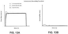
- the flow rate correction may be equal to the maximum allowable change in flow rate if the change in flow rate between the actual flow rate and the programmed flow rate is higher than the maximum allowable deviation or change. In further embodiments, the flow rate correction may be equal to the actual flow rate if the change in the flow rate between the actual flow rate and the programmed flow rate is less than or equal to the maximum allowable deviation or change. A difference between the change in flow rate and the maximum allowable deviation or change in flow rate may be stored in the memory 408 of the electronic control device 400 as a buffer deviation for use in determining a new flow rate correction in subsequent time intervals after the second time interval.
- the error in the amount of fluid that is actually delivered during the fluid delivery procedure may be spread over multiple time intervals instead of being accounted for only in a subsequent time interval to the time interval in which the error was accumulated. For example, a fraction of the difference between the change in flow rate and the maximum allowable deviation or change in flow rate may be added to each of a plurality of time intervals after the time interval in which the error was accumulated.
- the flow rate correction for each subsequent time interval may be based on a difference between the maximum allowable deviation and the deviation of the actual flow rate from the programmed flow rate over each subsequent time interval, and a buffer deviation from a previous time interval.
- the calculation of a new programmed flow rate can be repeated for each subsequent time interval, up to the last time interval of the fluid injection procedure. In this manner, the new programmed flow rate from a previous time interval is used as a programmed flow rate for the current time interval, and an updated programmed flow rate is calculated for the subsequent time interval.
- an example of injector logic that may be programmed into the at least one processor 404 of the electronic control device 400 may include the following steps:
- an example of injector logic that may be programmed into the at least one processor 404 of the electronic control device 400 may include the following steps:
- FIG. 6 illustrates a graphical relationship between the change in pressure versus the change in flow rate for one embodiment of an injector system using the injector logic described herein.
- a change in flow rate (mL/s) can be determined for the fluid injector based of an observed or determined change in pressure over a time interval (1 sec according to the embodiment of FIG. 6 ).
- FIG. 7 illustrates a graphical relationship of the resulting transformation calculation of the actual flow rate for specific programmed flow rates for one embodiment of an injector system using the injector logic of the present disclosure. Using the plot in FIG. 7 , a difference between the true flow rate output for the injector system is determined for an observed pressure change over a time interval (1 sec) for specific programmed fluid flow rates.
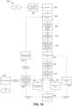
- a method 800 for improved fluid delivery using real-time, pressure-based control of one or more drive components 510a, 510b, 510n of a fluid injector system 100 during a fluid injection procedure will now be described with reference to FIG. 8 .
- a programmed flow rate for a specified time interval of the fluid delivery procedure and a maximum allowable change in the flow rate during any time interval are set at step 802.
- the programmed flow rate and the maximum allowable deviation or change in the flow rate may be stored in the memory 408 of the electronic control device 400.
- a first pressure is measured at the start of the time period and a second pressure is measured at the end of the time period.
- pressure may be measured using one or more force sensors 540 associated with the one or more drive components 510a, 510b, 510n and/or one or more pressure sensors 550 associated with one or more of fluid reservoirs 500a, 500b, 500n and/or fluid conduit 530.
- the machine learning model may be designed to receive, as an input, data associated with an injection procedure, such as a desired flow rate during execution of a fluid delivery procedure, and provide, as an output, instructions to the control device 400 to drive the one or more drive components 510a, 510b, 510n to deliver a desired volume of fluid at a desired flow rate.
- the fluid injector system 100 may store the machine learning model (e.g., for later use) in the memory of the control device 400.
Landscapes
- Health & Medical Sciences (AREA)
- Engineering & Computer Science (AREA)
- Public Health (AREA)
- General Health & Medical Sciences (AREA)
- Biomedical Technology (AREA)
- Heart & Thoracic Surgery (AREA)
- Life Sciences & Earth Sciences (AREA)
- Animal Behavior & Ethology (AREA)
- Anesthesiology (AREA)
- Vascular Medicine (AREA)
- Veterinary Medicine (AREA)
- Hematology (AREA)
- Epidemiology (AREA)
- Primary Health Care (AREA)
- Medical Informatics (AREA)
- Medicinal Chemistry (AREA)
- Bioinformatics & Cheminformatics (AREA)
- Chemical & Material Sciences (AREA)
- Business, Economics & Management (AREA)
- General Business, Economics & Management (AREA)
- Infusion, Injection, And Reservoir Apparatuses (AREA)
- Flow Control (AREA)
- Control Of Positive-Displacement Pumps (AREA)
Applications Claiming Priority (3)
| Application Number | Priority Date | Filing Date | Title |
|---|---|---|---|
| US201962938397P | 2019-11-21 | 2019-11-21 | |
| EP20824850.0A EP4062417B1 (de) | 2019-11-21 | 2020-11-20 | System und verfahren zur fluidfreisetzung unter verwendung einer druckbasierten motorsteuerung für fluidinjektoren |
| PCT/US2020/061474 WO2021102242A1 (en) | 2019-11-21 | 2020-11-20 | System and method for fluid delivery using pressure-based motor control for fluid injector devices |
Related Parent Applications (3)
| Application Number | Title | Priority Date | Filing Date |
|---|---|---|---|
| PCT/US2020/061474 Previously-Filed-Application WO2021102242A1 (en) | 2019-11-21 | 2020-11-20 | System and method for fluid delivery using pressure-based motor control for fluid injector devices |
| EP20824850.0A Division EP4062417B1 (de) | 2019-11-21 | 2020-11-20 | System und verfahren zur fluidfreisetzung unter verwendung einer druckbasierten motorsteuerung für fluidinjektoren |
| EP20824850.0A Division-Into EP4062417B1 (de) | 2019-11-21 | 2020-11-20 | System und verfahren zur fluidfreisetzung unter verwendung einer druckbasierten motorsteuerung für fluidinjektoren |
Publications (2)
| Publication Number | Publication Date |
|---|---|
| EP4578476A2 true EP4578476A2 (de) | 2025-07-02 |
| EP4578476A3 EP4578476A3 (de) | 2025-09-17 |
Family
ID=73835824
Family Applications (2)
| Application Number | Title | Priority Date | Filing Date |
|---|---|---|---|
| EP24218987.6A Pending EP4578476A3 (de) | 2019-11-21 | 2020-11-20 | System und verfahren zur fluidfreisetzung unter verwendung einer druckbasierten motorsteuerung für fluidinjektoren |
| EP20824850.0A Active EP4062417B1 (de) | 2019-11-21 | 2020-11-20 | System und verfahren zur fluidfreisetzung unter verwendung einer druckbasierten motorsteuerung für fluidinjektoren |
Family Applications After (1)
| Application Number | Title | Priority Date | Filing Date |
|---|---|---|---|
| EP20824850.0A Active EP4062417B1 (de) | 2019-11-21 | 2020-11-20 | System und verfahren zur fluidfreisetzung unter verwendung einer druckbasierten motorsteuerung für fluidinjektoren |
Country Status (6)
| Country | Link |
|---|---|
| US (2) | US12070577B2 (de) |
| EP (2) | EP4578476A3 (de) |
| JP (1) | JP7828277B2 (de) |
| CN (1) | CN114730625A (de) |
| AU (1) | AU2020386623A1 (de) |
| WO (1) | WO2021102242A1 (de) |
Families Citing this family (3)
| Publication number | Priority date | Publication date | Assignee | Title |
|---|---|---|---|---|
| EP4143840B1 (de) | 2020-04-30 | 2026-04-22 | Bayer HealthCare LLC | System, vorrichtung und verfahren zur sicherung des wohlbefindens von patienten zur flüssigkeitsinjektion |
| CN114810567B (zh) * | 2022-03-29 | 2024-05-14 | 深圳市好克医疗仪器股份有限公司 | 肠内营养泵的控制方法、系统、肠内营养泵及存储介质 |
| US20250161564A1 (en) * | 2023-11-21 | 2025-05-22 | B. Braun Medical Inc. | Preventing overinfusion in programmable infusions |
Citations (10)
| Publication number | Priority date | Publication date | Assignee | Title |
|---|---|---|---|---|
| US7540856B2 (en) | 2000-02-07 | 2009-06-02 | Medrad, Inc. | Front-loading medical injector adapted to releasably engage a syringe regardless of the orientation of the syringe with respect to the injector |
| US7553294B2 (en) | 2002-05-30 | 2009-06-30 | Medrad, Inc. | Syringe plunger sensing mechanism for a medical injector |
| US7563249B2 (en) | 2002-12-20 | 2009-07-21 | Medrad, Inc. | Syringe having an alignment flange, an extending lip and a radial expansion section of reduced wall thickness |
| US8945051B2 (en) | 2009-07-24 | 2015-02-03 | Bayer Medical Care Inc. | Multi-fluid medical injector system and methods of operation |
| US9173995B1 (en) | 2014-10-28 | 2015-11-03 | Bayer Healthcare Llc | Self-orienting syringe and syringe interface |
| US20180161496A1 (en) | 2015-04-24 | 2018-06-14 | Bayer Healthcare Llc | Syringe with rolling diaphragm |
| US10124110B2 (en) | 2013-10-18 | 2018-11-13 | Bayer Healthcare Llc | Magnetic pressure jacket for fluid injector |
| US10507319B2 (en) | 2015-01-09 | 2019-12-17 | Bayer Healthcare Llc | Multiple fluid delivery system with multi-use disposable set and features thereof |
| US10549084B2 (en) | 2014-01-10 | 2020-02-04 | Bayer Healthcare Llc | Single-use disposable set connector |
| US10583256B2 (en) | 2014-04-25 | 2020-03-10 | Bayer Healthcare Llc | Syringe with rolling diaphragm |
Family Cites Families (22)
| Publication number | Priority date | Publication date | Assignee | Title |
|---|---|---|---|---|
| US3701345A (en) | 1970-09-29 | 1972-10-31 | Medrad Inc | Angiographic injector equipment |
| US4006736A (en) | 1974-11-27 | 1977-02-08 | Medrad, Inc. | Angiographic injector |
| US7766873B2 (en) | 1998-10-29 | 2010-08-03 | Medtronic Minimed, Inc. | Method and apparatus for detecting occlusions in an ambulatory infusion pump |
| US6673033B1 (en) | 1999-11-24 | 2004-01-06 | Medrad, Inc. | Injectors, injector systems and injector control |
| US8141844B2 (en) * | 2005-10-26 | 2012-03-27 | Codman NeuroSciences Sàrl | Flow rate accuracy of a fluidic delivery system |
| CN104162200B (zh) * | 2006-02-09 | 2018-03-27 | 德卡产品有限公司 | 外围系统 |
| CN101557844B (zh) | 2007-05-04 | 2014-04-09 | 马林克罗特有限公司 | 用于控制医用流体注入的方法 |
| US8215157B2 (en) * | 2007-10-04 | 2012-07-10 | Baxter International Inc. | System and method for measuring liquid viscosity in a fluid delivery system |
| US20090093774A1 (en) * | 2007-10-04 | 2009-04-09 | Baxter International Inc. | Ambulatory pump with intelligent flow control |
| US7880624B2 (en) | 2008-01-08 | 2011-02-01 | Baxter International Inc. | System and method for detecting occlusion using flow sensor output |
| US9333297B2 (en) * | 2008-05-08 | 2016-05-10 | Minipumps, Llc | Drug-delivery pump with intelligent control |
| US8628510B2 (en) * | 2010-12-22 | 2014-01-14 | Medtronic Minimed, Inc. | Monitoring the operating health of a force sensor in a fluid infusion device |
| US9649436B2 (en) * | 2011-09-21 | 2017-05-16 | Bayer Healthcare Llc | Assembly method for a fluid pump device for a continuous multi-fluid delivery system |
| CN104507516B (zh) | 2012-05-24 | 2018-02-16 | 德卡产品有限公司 | 用于输注流体的装置 |
| US20140088508A1 (en) | 2012-09-24 | 2014-03-27 | Patrick Ryan | Drug-delivery devices with integrated needle-insertion mechanism |
| US9517305B2 (en) | 2013-03-15 | 2016-12-13 | Bayer Healthcare Llc | Medical fluid injector |
| JP6404209B2 (ja) | 2013-04-11 | 2018-10-10 | 株式会社根本杏林堂 | 薬液注入装置および薬液注入システム |
| WO2017032498A1 (en) | 2015-08-24 | 2017-03-02 | Fresenius Vial Sas | Infusion device and method for administering a medical fluid to a patient |
| AU2018323442B2 (en) | 2017-08-31 | 2024-06-27 | Bayer Healthcare Llc | Fluid path impedance assessment for improving fluid delivery performance |
| CA3097557A1 (en) | 2018-04-19 | 2019-10-24 | Bayer Healthcare Llc | System and method for air detection in fluid injector |
| CA3110859A1 (en) * | 2018-08-28 | 2020-03-05 | Bayer Healthcare Llc | Fluid injector system, method of preventing fluid backflow, and computer program product |
| CN115836355A (zh) * | 2020-06-02 | 2023-03-21 | 拜耳医药保健有限责任公司 | 基于液压阻力控制流体注射系统的系统、方法和计算机程序产品 |
-
2020
- 2020-11-20 AU AU2020386623A patent/AU2020386623A1/en active Pending
- 2020-11-20 EP EP24218987.6A patent/EP4578476A3/de active Pending
- 2020-11-20 US US17/776,332 patent/US12070577B2/en active Active
- 2020-11-20 CN CN202080080816.3A patent/CN114730625A/zh active Pending
- 2020-11-20 JP JP2022529665A patent/JP7828277B2/ja active Active
- 2020-11-20 WO PCT/US2020/061474 patent/WO2021102242A1/en not_active Ceased
- 2020-11-20 EP EP20824850.0A patent/EP4062417B1/de active Active
-
2024
- 2024-08-23 US US18/813,904 patent/US20240408301A1/en active Pending
Patent Citations (10)
| Publication number | Priority date | Publication date | Assignee | Title |
|---|---|---|---|---|
| US7540856B2 (en) | 2000-02-07 | 2009-06-02 | Medrad, Inc. | Front-loading medical injector adapted to releasably engage a syringe regardless of the orientation of the syringe with respect to the injector |
| US7553294B2 (en) | 2002-05-30 | 2009-06-30 | Medrad, Inc. | Syringe plunger sensing mechanism for a medical injector |
| US7563249B2 (en) | 2002-12-20 | 2009-07-21 | Medrad, Inc. | Syringe having an alignment flange, an extending lip and a radial expansion section of reduced wall thickness |
| US8945051B2 (en) | 2009-07-24 | 2015-02-03 | Bayer Medical Care Inc. | Multi-fluid medical injector system and methods of operation |
| US10124110B2 (en) | 2013-10-18 | 2018-11-13 | Bayer Healthcare Llc | Magnetic pressure jacket for fluid injector |
| US10549084B2 (en) | 2014-01-10 | 2020-02-04 | Bayer Healthcare Llc | Single-use disposable set connector |
| US10583256B2 (en) | 2014-04-25 | 2020-03-10 | Bayer Healthcare Llc | Syringe with rolling diaphragm |
| US9173995B1 (en) | 2014-10-28 | 2015-11-03 | Bayer Healthcare Llc | Self-orienting syringe and syringe interface |
| US10507319B2 (en) | 2015-01-09 | 2019-12-17 | Bayer Healthcare Llc | Multiple fluid delivery system with multi-use disposable set and features thereof |
| US20180161496A1 (en) | 2015-04-24 | 2018-06-14 | Bayer Healthcare Llc | Syringe with rolling diaphragm |
Also Published As
| Publication number | Publication date |
|---|---|
| JP2023503453A (ja) | 2023-01-30 |
| JP7828277B2 (ja) | 2026-03-11 |
| US12070577B2 (en) | 2024-08-27 |
| AU2020386623A1 (en) | 2022-06-02 |
| EP4062417B1 (de) | 2025-01-15 |
| WO2021102242A1 (en) | 2021-05-27 |
| EP4578476A3 (de) | 2025-09-17 |
| CN114730625A (zh) | 2022-07-08 |
| US20240408301A1 (en) | 2024-12-12 |
| EP4062417A1 (de) | 2022-09-28 |
| US20220395633A1 (en) | 2022-12-15 |
Similar Documents
| Publication | Publication Date | Title |
|---|---|---|
| US11826553B2 (en) | Fluid path impedance assessment for improving fluid delivery performance | |
| US20240408301A1 (en) | System and method for fluid delivery using pressure-based motor control for fluid injector devices | |
| AU2019256461B2 (en) | System and method for air detection in fluid injector | |
| EP4158642B1 (de) | Verfahren zur steuerung eines flüssigkeitseinspritzsystems auf basis von hydraulischem widerstand | |
| US20230069601A1 (en) | Fluid injector system volume compensation system and method | |
| AU2019329731B2 (en) | Fluid injector system, method of preventing fluid backflow, and computer program product | |
| JP7842687B2 (ja) | 流体インジェクタデバイスのための閉塞の検出および改善された圧力制限挙動のためのシステム、方法、およびコンピュータプログラム製品 |
Legal Events
| Date | Code | Title | Description |
|---|---|---|---|
| PUAI | Public reference made under article 153(3) epc to a published international application that has entered the european phase |
Free format text: ORIGINAL CODE: 0009012 |
|
| STAA | Information on the status of an ep patent application or granted ep patent |
Free format text: STATUS: THE APPLICATION HAS BEEN PUBLISHED |
|
| AC | Divisional application: reference to earlier application |
Ref document number: 4062417 Country of ref document: EP Kind code of ref document: P |
|
| AK | Designated contracting states |
Kind code of ref document: A2 Designated state(s): AL AT BE BG CH CY CZ DE DK EE ES FI FR GB GR HR HU IE IS IT LI LT LU LV MC MK MT NL NO PL PT RO RS SE SI SK SM TR |
|
| REG | Reference to a national code |
Ref country code: DE Ref legal event code: R079 Free format text: PREVIOUS MAIN CLASS: A61M0005142000 Ipc: G16H0020170000 |
|
| PUAL | Search report despatched |
Free format text: ORIGINAL CODE: 0009013 |
|
| AK | Designated contracting states |
Kind code of ref document: A3 Designated state(s): AL AT BE BG CH CY CZ DE DK EE ES FI FR GB GR HR HU IE IS IT LI LT LU LV MC MK MT NL NO PL PT RO RS SE SI SK SM TR |
|
| RIC1 | Information provided on ipc code assigned before grant |
Ipc: G16H 20/17 20180101AFI20250813BHEP Ipc: A61M 5/00 20060101ALI20250813BHEP Ipc: G16H 40/63 20180101ALI20250813BHEP Ipc: A61M 5/14 20060101ALI20250813BHEP Ipc: A61M 5/145 20060101ALI20250813BHEP Ipc: A61M 5/142 20060101ALI20250813BHEP |
|
| STAA | Information on the status of an ep patent application or granted ep patent |
Free format text: STATUS: REQUEST FOR EXAMINATION WAS MADE |
|
| 17P | Request for examination filed |
Effective date: 20260317 |