EP4578534A2 - Mehrteiliger filtrationsbehälter - Google Patents
Mehrteiliger filtrationsbehälter Download PDFInfo
- Publication number
- EP4578534A2 EP4578534A2 EP25176181.3A EP25176181A EP4578534A2 EP 4578534 A2 EP4578534 A2 EP 4578534A2 EP 25176181 A EP25176181 A EP 25176181A EP 4578534 A2 EP4578534 A2 EP 4578534A2
- Authority
- EP
- European Patent Office
- Prior art keywords
- filtration
- beams
- pressure vessel
- elements
- adjacent
- Prior art date
- Legal status (The legal status is an assumption and is not a legal conclusion. Google has not performed a legal analysis and makes no representation as to the accuracy of the status listed.)
- Pending
Links
Images


Classifications
-
- B—PERFORMING OPERATIONS; TRANSPORTING
- B01—PHYSICAL OR CHEMICAL PROCESSES OR APPARATUS IN GENERAL
- B01D—SEPARATION
- B01D63/00—Apparatus in general for separation processes using semi-permeable membranes
- B01D63/02—Hollow fibre modules
- B01D63/04—Hollow fibre modules comprising multiple hollow fibre assemblies
- B01D63/046—Hollow fibre modules comprising multiple hollow fibre assemblies in separate housings
-
- B—PERFORMING OPERATIONS; TRANSPORTING
- B01—PHYSICAL OR CHEMICAL PROCESSES OR APPARATUS IN GENERAL
- B01D—SEPARATION
- B01D61/00—Processes of separation using semi-permeable membranes, e.g. dialysis, osmosis or ultrafiltration; Apparatus, accessories or auxiliary operations specially adapted therefor
- B01D61/02—Reverse osmosis; Hyperfiltration ; Nanofiltration
- B01D61/08—Apparatus therefor
-
- B—PERFORMING OPERATIONS; TRANSPORTING
- B01—PHYSICAL OR CHEMICAL PROCESSES OR APPARATUS IN GENERAL
- B01D—SEPARATION
- B01D61/00—Processes of separation using semi-permeable membranes, e.g. dialysis, osmosis or ultrafiltration; Apparatus, accessories or auxiliary operations specially adapted therefor
- B01D61/14—Ultrafiltration; Microfiltration
- B01D61/18—Apparatus therefor
-
- B—PERFORMING OPERATIONS; TRANSPORTING
- B01—PHYSICAL OR CHEMICAL PROCESSES OR APPARATUS IN GENERAL
- B01D—SEPARATION
- B01D63/00—Apparatus in general for separation processes using semi-permeable membranes
- B01D63/02—Hollow fibre modules
-
- B—PERFORMING OPERATIONS; TRANSPORTING
- B01—PHYSICAL OR CHEMICAL PROCESSES OR APPARATUS IN GENERAL
- B01D—SEPARATION
- B01D63/00—Apparatus in general for separation processes using semi-permeable membranes
- B01D63/02—Hollow fibre modules
- B01D63/04—Hollow fibre modules comprising multiple hollow fibre assemblies
-
- B—PERFORMING OPERATIONS; TRANSPORTING
- B01—PHYSICAL OR CHEMICAL PROCESSES OR APPARATUS IN GENERAL
- B01D—SEPARATION
- B01D65/00—Accessories or auxiliary operations, in general, for separation processes or apparatus using semi-permeable membranes
-
- B—PERFORMING OPERATIONS; TRANSPORTING
- B01—PHYSICAL OR CHEMICAL PROCESSES OR APPARATUS IN GENERAL
- B01D—SEPARATION
- B01D2313/00—Details relating to membrane modules or apparatus
- B01D2313/02—Specific tightening or locking mechanisms
- B01D2313/025—Specific membrane holders
-
- B—PERFORMING OPERATIONS; TRANSPORTING
- B01—PHYSICAL OR CHEMICAL PROCESSES OR APPARATUS IN GENERAL
- B01D—SEPARATION
- B01D2313/00—Details relating to membrane modules or apparatus
- B01D2313/06—External membrane module supporting or fixing means
-
- B—PERFORMING OPERATIONS; TRANSPORTING
- B01—PHYSICAL OR CHEMICAL PROCESSES OR APPARATUS IN GENERAL
- B01D—SEPARATION
- B01D2313/00—Details relating to membrane modules or apparatus
- B01D2313/20—Specific housing
-
- B—PERFORMING OPERATIONS; TRANSPORTING
- B01—PHYSICAL OR CHEMICAL PROCESSES OR APPARATUS IN GENERAL
- B01D—SEPARATION
- B01D2313/00—Details relating to membrane modules or apparatus
- B01D2313/21—Specific headers, end caps
-
- B—PERFORMING OPERATIONS; TRANSPORTING
- B01—PHYSICAL OR CHEMICAL PROCESSES OR APPARATUS IN GENERAL
- B01D—SEPARATION
- B01D2313/00—Details relating to membrane modules or apparatus
- B01D2313/23—Specific membrane protectors, e.g. sleeves or screens
-
- B—PERFORMING OPERATIONS; TRANSPORTING
- B01—PHYSICAL OR CHEMICAL PROCESSES OR APPARATUS IN GENERAL
- B01D—SEPARATION
- B01D2313/00—Details relating to membrane modules or apparatus
- B01D2313/26—Specific gas distributors or gas intakes
-
- B—PERFORMING OPERATIONS; TRANSPORTING
- B01—PHYSICAL OR CHEMICAL PROCESSES OR APPARATUS IN GENERAL
- B01D—SEPARATION
- B01D2313/00—Details relating to membrane modules or apparatus
- B01D2313/44—Cartridge types
-
- B—PERFORMING OPERATIONS; TRANSPORTING
- B01—PHYSICAL OR CHEMICAL PROCESSES OR APPARATUS IN GENERAL
- B01D—SEPARATION
- B01D2313/00—Details relating to membrane modules or apparatus
- B01D2313/54—Modularity of membrane module elements
-
- B—PERFORMING OPERATIONS; TRANSPORTING
- B01—PHYSICAL OR CHEMICAL PROCESSES OR APPARATUS IN GENERAL
- B01D—SEPARATION
- B01D2315/00—Details relating to the membrane module operation
- B01D2315/06—Submerged-type; Immersion type
-
- B—PERFORMING OPERATIONS; TRANSPORTING
- B01—PHYSICAL OR CHEMICAL PROCESSES OR APPARATUS IN GENERAL
- B01D—SEPARATION
- B01D2321/00—Details relating to membrane cleaning, regeneration, sterilization or to the prevention of fouling
- B01D2321/18—Use of gases
-
- B—PERFORMING OPERATIONS; TRANSPORTING
- B01—PHYSICAL OR CHEMICAL PROCESSES OR APPARATUS IN GENERAL
- B01D—SEPARATION
- B01D2321/00—Details relating to membrane cleaning, regeneration, sterilization or to the prevention of fouling
- B01D2321/18—Use of gases
- B01D2321/185—Aeration
-
- Y—GENERAL TAGGING OF NEW TECHNOLOGICAL DEVELOPMENTS; GENERAL TAGGING OF CROSS-SECTIONAL TECHNOLOGIES SPANNING OVER SEVERAL SECTIONS OF THE IPC; TECHNICAL SUBJECTS COVERED BY FORMER USPC CROSS-REFERENCE ART COLLECTIONS [XRACs] AND DIGESTS
- Y02—TECHNOLOGIES OR APPLICATIONS FOR MITIGATION OR ADAPTATION AGAINST CLIMATE CHANGE
- Y02W—CLIMATE CHANGE MITIGATION TECHNOLOGIES RELATED TO WASTEWATER TREATMENT OR WASTE MANAGEMENT
- Y02W10/00—Technologies for wastewater treatment
- Y02W10/10—Biological treatment of water, waste water, or sewage
Definitions
- This invention relates to multi-element filtration vessels.
- Multi-element filtration vessels are used widely in water treatment facilities to purify water, and also as reactors in various chemical manufacturing processes.
- Semi-permeable membranes are assembled within elements, which are mounted vertically in an array within the vessel.
- a feed fluid is often fed upwardly through the elements, where it is separated by the membranes into a concentrate and a permeate.
- An aerating gas is usually introduced into the vessel at a point below the elements.
- the aerating gas can perform several useful functions.
- gas bubbles provide buoyancy, assisting with the transfer of the feed fluid between fibers or through the capillaries in the fibers.
- the aerating gas also can perform a cleaning function, and improve fluid mixing.
- One or more supports within the vessel bear the weight of the elements and maintain them in their proper positions.
- the elements are entirely supported and aligned by an upper plate.
- a lower support is used, typically in conjunction with an upper plate.
- the weight of the elements may be borne by the upper plate alone, in which case the lower support performs only an alignment function; alternatively the weight of the elements is borne by the lower plate (with the upper plate providing alignment) or distributed between the upper plate and lower support, with the lower support also serving to align the bottom ends of the elements.
- the lower support typically has taken the form of a perforated plate.
- the lower ends of the elements can align with the perforations so that the feed fluid and aerating gas can pass from below the lower support and into the elements.
- a problem with this design is that the perforated plate is often quite massive; large multi-element filtration vessels may have diameters of 1.5 meters or greater.
- the plate must be very rigid and often quite thick to span such a wide diameter. Very large plates are expensive, difficult to transport and assemble into the vessels, and susceptible to deforming under pressure or weight.
- This invention is in one aspect a multi-element filtration apparatus, the apparatus comprising
- the invention is a filtration element comprising
- the invention is a filtration apparatus comprising
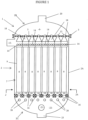
- multi-element filtration apparatus 1 includes pressure vessel 2, illustrated in cross-section, and formed of a central section 2A and upper and lower sections 2B and 2C.
- the pressure vessel is cylindrical and suitable for operation with inside pressures exceeding at least two bars above the outside pressure.
- upper section 2B is mounted to central section 2A via flange joint 3
- lower section 2C is mounted to or integral with central section 2A.
- Upper support 5 is mounted within pressure vessel 2 to provide support and alignment for filtration elements 8 and to separate upper chamber 6 from main chamber 7. In the embodiment shown, the periphery of upper support 5 is clamped and sealed between the central and upper sections 2A and 2B of pressure vessel 2 at the region of flange joint 3.
- One or more bottom through-holes 19 ( Figures 5 and 6 ) through tube sheet 30 permit the feed fluid and aeration gas to enter body portion 9 through bottom end 10.
- the feed fluid is separated into a permeate and a concentrate (or reject) by passing through filtration membrane(s) such as hollow fiber membranes 17 in (shown in Figure 6 ) residing within body portion 9.
- discharge openings 14 allow concentrate to leave body portion 9 of filtration elements 8 and be discharged into main chamber 7. Fluid is removed from main chamber 7 via a discharge port such as discharge port 15.
- the discharge port can also be near the middle or the lower part of main chamber 7.
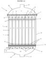
- a canted plate such as canted plate 36 of Figure 10 may be provided to direct concentrate to upper discharge port 15 and to avoid mixing concentrate with feed fluid within lower portions of main chamber 7. If present, canted plate 36 is provided with openings to allow filtration elements 8 to pass through, and in such a case, canted plate 36 can also perform an alignment and/or support function.
- Aeration gas typically vents from filtration elements 8 with the concentrate and is vented from pressure vessel 2 from a suitable vent (not shown) or through a concentrate discharge port through which the concentrate is removed from pressure vessel 2.
- Top ends 18 of filtration elements 8 are generally adapted to engage with openings in upper support plate 5 to form a seal and, via lumens 13 or other through-holes, provide one or more fluid flow paths through upper support plate 5 into upper chamber 6.
- Top ends 18 may include a cap or connector that is affixed to tubular shell 11 mechanically ( e.g ., by threads promoting a radial or axial O-ring seal), by use of suitable adhesives, or otherwise, in such a manner as to produce a seal between the cap or connector and tubular shell 11.
- a first set of multiple spaced beams 16 are mounted onto an interior surface of pressure vessel 2.
- the spaced beams 16 can be mounted on a ridge or other mechanical support structure within pressure vessel 2.
- the spaced beams 16 can be mounted permanently, such as by an adhesive or through welding them into place, or they may be mounted in a removable manner.
- the spaced beams 16 preferably are arranged parallel to each other, but non-parallel arrangements may be useful for particular arrangements of filtration elements 8 within pressure vessel 2.
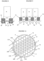
- the spaced beams 16 can be individually mounted within pressure vessel 2 or may be assembled into an alignment structure such as the peripheral supports 24 shown in Figures 3A, 3B, and 3C .
- the alignment structure can align and hold beams 16 together, creating a unitary structure.
- Spaced beams 16 can have any convenient cross-sectional geometry provided the beams engage with bottom ends 10 of filtration elements 8 as described herein.
- a simple rectangular cross-section is entirely suitable, although spaced beams 16 can have alternative cross-sectional geometries such as squares, triangles, trapezoids, hexagons, other regular or irregular polygons, I-beams and circles.
- the cross-section of any beam 16 may vary along its length as shown, for example, in Figure 4 where beam 16 has a greater height (H 1 ) in the middle than at the ends (H 0 ).
- the various beams 16 do not all need to have the same geometry or dimensions.
- spaced beams 16 are selected to meet their mechanical requirements.
- suitable materials of construction include metals such as steel, stainless steel, aluminum or magnesium, polymers (such as polyvinyl chloride, a polyester or a polyolefin) and reinforced organic polymers such as fiber-reinforced thermoplastic or thermoset resins.
- metals such as steel, stainless steel, aluminum or magnesium
- polymers such as polyvinyl chloride, a polyester or a polyolefin
- reinforced organic polymers such as fiber-reinforced thermoplastic or thermoset resins.
- metal materials may be encapsulated within a polymeric coating.
- a preferred material for at least the longer center beams is a fiber-reinforced thermoplastic or thermoset resin.
- Bottom ends 10 of filtration elements 8 each are adapted to rest upon an adjacent pair of beams 16 and to extend downwardly between those adjacent beams 16.
- the spacing of each adjacent pair of beams 16 preferably is chosen in conjunction with the geometry of bottom ends 10 of filtration elements 8 so that bottom ends 10 fit snugly within the space between adjacent beams 16.
- the lower section 10B of bottom ends 10 may be tapered inwardly to facilitate positioning and alignment between beams 16.
- the taper makes an angle of between 15 and 75 degrees, more preferably between 30 and 60 degrees, with the vertical in the X-Z plane, where X is the direction from shoulder 10D to opposing shoulder 10D'.
- the filtration elements 8 can be arranged within pressure vessel 2 in any convenient manner. They may be arranged in an array or other defined pattern, or randomly. In a preferred embodiment such as is shown in Figure 2 , the filtration elements 8 are arranged in a hexagonal close packing arrangement, as this enables facile support of each row 32 ( Figure 2 ) of multiple filtration elements 8 by two adjacent spaced beams 16. With elements arranged in hexagonal close packing, adjacent parallel rows 32 of multiple filtration elements 8 can be supported by a common beam 16 and the adjacent beams 16 on either side of the common beam 16.
- Optional positioning elements such as brackets 25 in Figure 3A and alignment notches 31 in Figure 3B may be incorporated or affixed to beams 16 to align filtration elements 8 and prevent them from moving in the direction of beams 16 i.e., along the space defined by the two adjacent beams 16 on which the particular filtration element 8 rests.
- beams 16 and bottom ends 10 of filtration elements 8 have corresponding positioning elements that engage and/or otherwise mate with each other to align filtration elements 8 into a fixed position relative to the beams 16 to which it engages.
- shoulders 10D may include canted downward protrusions adapted to engage with notches 31 of beams 16 ( Figure 3B ). Such a canted downward protrusion may form an angle of between 15 and 75 degrees, more preferably between 30 and 60 degrees, with the beam direction Y and a vertical Z of the corresponding filtration element 8.
- Cavity 27 provides a fluid path for feed fluid and a gas supplied by aerators 26 to travel upwardly through cavity 27 to one or more through-holes 19 that admit the feed fluid and aerating gas into the interior of the corresponding filtration element 8.
- cavity 27 includes an upper cavity 27A and a lower cavity 27B.
- upper cavity 27A resides above the level of beams 16 and may function as a headspace for the aeration gas provided by aerators 16.
- the headspace may have a vertical extension of at least 0.5 cm or at least 1 cm, and, for example, up to 10 cm or up to 5.1 cm.
- Lower cavity 27B extends between the adjacent beams.
- Figure 5B illustrates a bottom end 10 adapted to form a cavity together with adjacent beams 16.
- lower section 10B has one or more open sides 10C.
- adjacent beams 16 abut lower section 10B on each open side, thereby producing lower cavity 27B.
- lower section 10B has tapered lower section 12.
- an element that is approximately positioned between adjacent beams 16 can be nudged (in a direction approximately perpendicular to the beams 16) into a more correct position through interaction of the tapered lower section 12 with a beam 16.
- Tapered lower section 12 may make an angle of between 15 and 75 degrees, and more preferably between 30 and 60 degrees, with both the vertical axis (Z) of the element and with the element width direction ( X ). In this way, the lower section 10B of an element is made more easily able to be positioned in place between adjacent beams 16.
- bottom end 10 in Figures 5A, 5B and 6 is not necessary.
- Alternative bottom end geometries are entirely suitable provided bottom end 10 is supported by adjacent spaced beams 16 and extends downwardly between the adjacent spaced beams 16, and the bottom end by itself or together with the adjacent beams forms a cavity 27 that provides a feed path for a feed fluid and a gas supplied by the aerator 26 to travel upwardly through cavity 27 to the through-holes 19 in the bottom end 10.
- Aerators 26 are provided to supply an aeration gas to bottom ends 10 of multiple filtration elements 8.
- aerator it is meant any device that produces gas bubbles when an aeration gas is flowed into the aerator and out into lower portion 22.
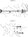
- a gas sparger or other device with small openings (such as gas outlet holes 29 in Figures 1A and 7 ) that cause bubbles to form is entirely suitable.
- the openings preferably have dimensions of at least 0.25 mm, at least 0.5 mm or at least 1 mm and up to 10 mm, up to 7.5, up to 5 mm, or up to 4 mm.
- the aeration gas may be air, oxygen, nitrogen, helium, argon or other material that is gaseous at standard temperature and pressure, or a mixture of any two or more of such gasses.
- Removable aerators 26 may include a section 38 that is exterior of pressure vessel 2, and another section 37 having gas outlet holes 29 that extends into the interior of pressure vessel 2. The entire inner section is adapted to fit through opening 34 for insertion and removal. Removable aerators 26 preferably are closed at distal end 39. Removable aerators 26 preferably also include a releasable connection for engaging and sealing to an external gas source, potentially via a manifold 42 ( Figures 10 and 12 ). Manifold 42 may be used to connect multiple aerators 26 the external gas source.
- a removable aerator may be used to best advantage when the pressure vessel contains a plurality of filtration elements 8 arranged in row 32, and removable aerators 26 extend parallel to the rows.
- some or all of removable aerators 26 are located below one or more rows 32 of filtration elements 8, and gas outlet holes 29 are arranged to be positioned under each individual filtration element 8 in the corresponding row 32.
- One or more removable aerators 26 may be located between two adjacent rows 32 of filtration elements 8, the gas outlet holes 29 being arranged to provide air to elements in the two adjacent rows 32 on each side of that aerator. Both of these configurations are illustrated in Figure 11 , wherein removable aerators 26A are located between two adjacent rows 32 of filtration elements 8 and removable aerators 26B each are positioned below a row 32 of filtration elements 8.
- Each removable aerator 26 advantageously services a similar number of elements.
- multiple removable aerators 26 extend into pressure vessel 2 and no aerator services more than 50% more, more preferably more than 25% more, elements than any other removable aerator 26 in pressure vessel 2.
- Removable aerators 26 can, if desired, be used in conjunction with a conventional lower support in the form of a perforated plate, or which lack a lower support for filtration elements 8.
- a feed fluid is introduced into pressure vessel 2 of multi-element filtration apparatus 1 via feed inlet port 21.
- Pressure vessel 2 is filled at least to the level of bottom ends 10 so feed fluid enters filtration elements 8 through cavities 27 in bottom ends 10 and passes through through-holes 19 to enter into the interior portions of filtration elements 8.
- An aeration supply system (not shown) supplies pressurized gas to aerators 26. The aeration gas bubbles upward through cavities 27 and through-holes 19 to enter filtration elements 8.
- permeate and concentrate are taken separately from at or near top ends 18 of filtration elements 8.
- permeate can be withdrawn from filtration elements 8 through lumens 13, that extend through tube sheet 30A ( Figure 6 ), collected in upper chamber 6 of pressure vessel 2, and removed via upper discharge port 20.
- Concentrate and aeration gas are discharged from filtration elements 8 through discharge openings 14, with concentrate being removed from pressure vessel 2 via discharge port 15.
- Aeration gas can be vented through discharge port 15 or a separate air vent (not shown).
- Particulate matter that accumulates within main chamber 7 falls under force of gravity to the bottom of main chamber 7, where it passes through fluid passages 4 into lower portion 22 of main chamber 7.
- Particulate matter accumulating in lower portion 22 of main chamber 7 is easily removed, such as, for example, by taking a purge stream out of pressure vessel 2, such as via bottom drain 23.
- Particulate matter may include, for example, solid material that has accumulated on the membrane surface and has been removed, solid materials carried in with the feed fluid; solids materials that may precipitate during the filtration process or otherwise within pressure vessel 2; biological matter such as algae, bacterial colonies, mold and the like that may grow within pressure vessel 2; rust particles, scale, and the like. The ability to remove this particulate matter is an important advantage of the first aspect of this invention.
Landscapes
- Chemical & Material Sciences (AREA)
- Chemical Kinetics & Catalysis (AREA)
- Engineering & Computer Science (AREA)
- Water Supply & Treatment (AREA)
- Nanotechnology (AREA)
- Aeration Devices For Treatment Of Activated Polluted Sludge (AREA)
- Biological Treatment Of Waste Water (AREA)
- Filtering Of Dispersed Particles In Gases (AREA)
- Separation Using Semi-Permeable Membranes (AREA)
- Devices And Processes Conducted In The Presence Of Fluids And Solid Particles (AREA)
- Separation By Low-Temperature Treatments (AREA)
Applications Claiming Priority (3)
| Application Number | Priority Date | Filing Date | Title |
|---|---|---|---|
| CN2021093191 | 2021-05-12 | ||
| EP22706969.7A EP4337370A1 (de) | 2021-05-12 | 2022-02-15 | Mehrteiliger filtrationsbehälter |
| PCT/US2022/016405 WO2022240460A1 (en) | 2021-05-12 | 2022-02-15 | Multi-element filtration vessel |
Related Parent Applications (1)
| Application Number | Title | Priority Date | Filing Date |
|---|---|---|---|
| EP22706969.7A Division EP4337370A1 (de) | 2021-05-12 | 2022-02-15 | Mehrteiliger filtrationsbehälter |
Publications (2)
| Publication Number | Publication Date |
|---|---|
| EP4578534A2 true EP4578534A2 (de) | 2025-07-02 |
| EP4578534A3 EP4578534A3 (de) | 2025-11-19 |
Family
ID=80495880
Family Applications (2)
| Application Number | Title | Priority Date | Filing Date |
|---|---|---|---|
| EP22706969.7A Pending EP4337370A1 (de) | 2021-05-12 | 2022-02-15 | Mehrteiliger filtrationsbehälter |
| EP25176181.3A Pending EP4578534A3 (de) | 2021-05-12 | 2022-02-15 | Mehrteiliger filtrationsbehälter |
Family Applications Before (1)
| Application Number | Title | Priority Date | Filing Date |
|---|---|---|---|
| EP22706969.7A Pending EP4337370A1 (de) | 2021-05-12 | 2022-02-15 | Mehrteiliger filtrationsbehälter |
Country Status (6)
| Country | Link |
|---|---|
| US (1) | US20250073643A1 (de) |
| EP (2) | EP4337370A1 (de) |
| CN (1) | CN118695895A (de) |
| AU (1) | AU2022272159A1 (de) |
| MX (1) | MX2023013197A (de) |
| WO (1) | WO2022240460A1 (de) |
Families Citing this family (2)
| Publication number | Priority date | Publication date | Assignee | Title |
|---|---|---|---|---|
| WO2023200663A1 (en) | 2022-04-15 | 2023-10-19 | Ddp Specialty Electronic Materials Us, Llc | Water treatment system with biocontactor |
| WO2024112476A1 (en) * | 2022-11-21 | 2024-05-30 | Ddp Specialty Electronic Materials Us, Llc | Multi-element filtration vessel |
Citations (5)
| Publication number | Priority date | Publication date | Assignee | Title |
|---|---|---|---|---|
| US20030075504A1 (en) | 1998-09-25 | 2003-04-24 | Fufang Zha | Apparatus and method for cleaning membrane filtration modules |
| WO2008141080A1 (en) | 2007-05-11 | 2008-11-20 | Zenon Technology Partnership | Membrane module with multiple bottom headers and filtration process |
| US7988855B2 (en) | 2003-10-21 | 2011-08-02 | Zenon Technology Partnership | Membrane bioreactor having single header membrane module |
| US20150238905A1 (en) | 2012-09-26 | 2015-08-27 | Tomasz Swiatek | Membrane Securement Device |
| CN105327621A (zh) | 2015-11-07 | 2016-02-17 | 海南立昇净水科技实业有限公司 | 一种端头部件,中空纤维膜组件和膜过滤单元 |
Family Cites Families (3)
| Publication number | Priority date | Publication date | Assignee | Title |
|---|---|---|---|---|
| KR102004581B1 (ko) * | 2012-07-05 | 2019-07-26 | 도레이 카부시키가이샤 | 중공사막 모듈 |
| JP5663634B2 (ja) * | 2013-07-16 | 2015-02-04 | 日立造船株式会社 | 分離膜モジュールの膜分離部材、分離膜モジュールにおける膜分離部材の取付装置および分離膜モジュール |
| US9802159B2 (en) * | 2015-07-09 | 2017-10-31 | Hamilton Sundstrand Corporation | Air separation module canister |
-
2022
- 2022-02-15 MX MX2023013197A patent/MX2023013197A/es unknown
- 2022-02-15 EP EP22706969.7A patent/EP4337370A1/de active Pending
- 2022-02-15 EP EP25176181.3A patent/EP4578534A3/de active Pending
- 2022-02-15 US US18/560,046 patent/US20250073643A1/en active Pending
- 2022-02-15 CN CN202280033738.0A patent/CN118695895A/zh active Pending
- 2022-02-15 WO PCT/US2022/016405 patent/WO2022240460A1/en not_active Ceased
- 2022-02-15 AU AU2022272159A patent/AU2022272159A1/en active Pending
Patent Citations (5)
| Publication number | Priority date | Publication date | Assignee | Title |
|---|---|---|---|---|
| US20030075504A1 (en) | 1998-09-25 | 2003-04-24 | Fufang Zha | Apparatus and method for cleaning membrane filtration modules |
| US7988855B2 (en) | 2003-10-21 | 2011-08-02 | Zenon Technology Partnership | Membrane bioreactor having single header membrane module |
| WO2008141080A1 (en) | 2007-05-11 | 2008-11-20 | Zenon Technology Partnership | Membrane module with multiple bottom headers and filtration process |
| US20150238905A1 (en) | 2012-09-26 | 2015-08-27 | Tomasz Swiatek | Membrane Securement Device |
| CN105327621A (zh) | 2015-11-07 | 2016-02-17 | 海南立昇净水科技实业有限公司 | 一种端头部件,中空纤维膜组件和膜过滤单元 |
Also Published As
| Publication number | Publication date |
|---|---|
| US20250073643A1 (en) | 2025-03-06 |
| AU2022272159A1 (en) | 2023-11-09 |
| EP4337370A1 (de) | 2024-03-20 |
| MX2023013197A (es) | 2023-12-14 |
| CN118695895A (zh) | 2024-09-24 |
| EP4578534A3 (de) | 2025-11-19 |
| WO2022240460A1 (en) | 2022-11-17 |
Similar Documents
| Publication | Publication Date | Title |
|---|---|---|
| JP4958779B2 (ja) | 正方形のmbrマニホールド・システム | |
| EP1527810B1 (de) | Permeatsammelsystem | |
| JP4531091B2 (ja) | 円筒形ろ過カートリッジを保持する圧力容器 | |
| US8449659B2 (en) | Liquid degassing membrane contactors, components, systems and related methods | |
| US8778055B2 (en) | High pressure liquid degassing membrane contactors and methods of manufacturing and use | |
| US7282146B2 (en) | Removal system for membranes in a membrane filtration system | |
| KR100199657B1 (ko) | 중공 섬유 카트리지 | |
| EP1599276B1 (de) | Tauchbares membranmodul mit austauschbaren membranelementen | |
| US8876945B2 (en) | High pressure liquid degassing membrane contactors and methods of manufacturing and use | |
| US7731848B2 (en) | Cartridge module of hollow fiber membranes | |
| EP0610323A1 (de) | Permeationsvorrichtung mit mehreren Bündeln. | |
| EP4578534A2 (de) | Mehrteiliger filtrationsbehälter | |
| US20100140153A1 (en) | Manifold block for reverse osmosis systems | |
| KR101798551B1 (ko) | 여과막 모듈 및 이것을 포함하는 여과 시스템 | |
| KR100856385B1 (ko) | Mbr용 분리막 모듈 지지프레임 | |
| JP4930366B2 (ja) | 中空糸膜モジュール | |
| AU2004203856B2 (en) | Vertical skein of hollow fiber membranes and method of maintaining clean fiber surfaces | |
| EP4622733A1 (de) | Mehrteiliger filtrationsbehälter | |
| EP1688174A1 (de) | Membranfiltrationstank und Prozess zum Filtern einer Flüssigkeit | |
| AU2004203855B2 (en) | Vertical skein of hollow fiber membranes and method of maintaining clean fiber surfaces | |
| JP2634837B2 (ja) | 膜処理装置 | |
| Côté | Christian Güngerich and Ulrich Mende | |
| CZ20033082A3 (cs) | Ponořený univerzálnístavebnicový membránový modul |
Legal Events
| Date | Code | Title | Description |
|---|---|---|---|
| PUAI | Public reference made under article 153(3) epc to a published international application that has entered the european phase |
Free format text: ORIGINAL CODE: 0009012 |
|
| STAA | Information on the status of an ep patent application or granted ep patent |
Free format text: STATUS: REQUEST FOR EXAMINATION WAS MADE |
|
| 17P | Request for examination filed |
Effective date: 20250513 |
|
| AC | Divisional application: reference to earlier application |
Ref document number: 4337370 Country of ref document: EP Kind code of ref document: P |
|
| AK | Designated contracting states |
Kind code of ref document: A2 Designated state(s): AL AT BE BG CH CY CZ DE DK EE ES FI FR GB GR HR HU IE IS IT LI LT LU LV MC MK MT NL NO PL PT RO RS SE SI SK SM TR |
|
| REG | Reference to a national code |
Ref country code: DE Ref legal event code: R079 Free format text: PREVIOUS MAIN CLASS: B01D0065000000 Ipc: B01D0061080000 |
|
| RIC1 | Information provided on ipc code assigned before grant |
Ipc: B01D 61/08 20060101AFI20250716BHEP Ipc: B01D 61/18 20060101ALI20250716BHEP Ipc: B01D 63/04 20060101ALI20250716BHEP Ipc: B01D 65/00 20060101ALI20250716BHEP |
|
| PUAL | Search report despatched |
Free format text: ORIGINAL CODE: 0009013 |
|
| RIC1 | Information provided on ipc code assigned before grant |
Ipc: B01D 63/04 20060101ALI20251008BHEP Ipc: B01D 65/00 20060101ALI20251008BHEP Ipc: B01D 61/08 20060101AFI20251008BHEP Ipc: B01D 61/18 20060101ALI20251008BHEP |
|
| AK | Designated contracting states |
Kind code of ref document: A3 Designated state(s): AL AT BE BG CH CY CZ DE DK EE ES FI FR GB GR HR HU IE IS IT LI LT LU LV MC MK MT NL NO PL PT RO RS SE SI SK SM TR |
|
| RIC1 | Information provided on ipc code assigned before grant |
Ipc: B01D 61/08 20060101AFI20251010BHEP Ipc: B01D 61/18 20060101ALI20251010BHEP Ipc: B01D 63/04 20060101ALI20251010BHEP Ipc: B01D 65/00 20060101ALI20251010BHEP |