EP4578562A1 - Système de nettoyage automatique basé sur une balle de nettoyage - Google Patents
Système de nettoyage automatique basé sur une balle de nettoyage Download PDFInfo
- Publication number
- EP4578562A1 EP4578562A1 EP24223327.8A EP24223327A EP4578562A1 EP 4578562 A1 EP4578562 A1 EP 4578562A1 EP 24223327 A EP24223327 A EP 24223327A EP 4578562 A1 EP4578562 A1 EP 4578562A1
- Authority
- EP
- European Patent Office
- Prior art keywords
- cleaning
- pipe
- ball
- pipes
- cleaning ball
- Prior art date
- Legal status (The legal status is an assumption and is not a legal conclusion. Google has not performed a legal analysis and makes no representation as to the accuracy of the status listed.)
- Granted
Links
Images



Classifications
-
- B—PERFORMING OPERATIONS; TRANSPORTING
- B08—CLEANING
- B08B—CLEANING IN GENERAL; PREVENTION OF FOULING IN GENERAL
- B08B9/00—Cleaning hollow articles by methods or apparatus specially adapted thereto
- B08B9/02—Cleaning pipes or tubes or systems of pipes or tubes
- B08B9/027—Cleaning the internal surfaces; Removal of blockages
- B08B9/04—Cleaning the internal surfaces; Removal of blockages using cleaning devices introduced into and moved along the pipes
- B08B9/053—Cleaning the internal surfaces; Removal of blockages using cleaning devices introduced into and moved along the pipes moved along the pipes by a fluid, e.g. by fluid pressure or by suction
- B08B9/057—Cleaning the internal surfaces; Removal of blockages using cleaning devices introduced into and moved along the pipes moved along the pipes by a fluid, e.g. by fluid pressure or by suction the cleaning devices being entrained discrete elements, e.g. balls, grinding elements, brushes
-
- B—PERFORMING OPERATIONS; TRANSPORTING
- B08—CLEANING
- B08B—CLEANING IN GENERAL; PREVENTION OF FOULING IN GENERAL
- B08B13/00—Accessories or details of general applicability for machines or apparatus for cleaning
-
- B—PERFORMING OPERATIONS; TRANSPORTING
- B08—CLEANING
- B08B—CLEANING IN GENERAL; PREVENTION OF FOULING IN GENERAL
- B08B3/00—Cleaning by methods involving the use or presence of liquid or steam
- B08B3/04—Cleaning involving contact with liquid
- B08B3/08—Cleaning involving contact with liquid the liquid having chemical or dissolving effect
-
- B—PERFORMING OPERATIONS; TRANSPORTING
- B08—CLEANING
- B08B—CLEANING IN GENERAL; PREVENTION OF FOULING IN GENERAL
- B08B9/00—Cleaning hollow articles by methods or apparatus specially adapted thereto
- B08B9/02—Cleaning pipes or tubes or systems of pipes or tubes
- B08B9/027—Cleaning the internal surfaces; Removal of blockages
- B08B9/032—Cleaning the internal surfaces; Removal of blockages by the mechanical action of a moving fluid, e.g. by flushing
-
- G—PHYSICS
- G01—MEASURING; TESTING
- G01D—MEASURING NOT SPECIALLY ADAPTED FOR A SPECIFIC VARIABLE; ARRANGEMENTS FOR MEASURING TWO OR MORE VARIABLES NOT COVERED IN A SINGLE OTHER SUBCLASS; TARIFF METERING APPARATUS; MEASURING OR TESTING NOT OTHERWISE PROVIDED FOR
- G01D21/00—Measuring or testing not otherwise provided for
- G01D21/02—Measuring two or more variables by means not covered by a single other subclass
-
- B—PERFORMING OPERATIONS; TRANSPORTING
- B08—CLEANING
- B08B—CLEANING IN GENERAL; PREVENTION OF FOULING IN GENERAL
- B08B1/00—Cleaning by methods involving the use of tools
- B08B1/50—Cleaning by methods involving the use of tools involving cleaning of the cleaning members
- B08B1/52—Cleaning by methods involving the use of tools involving cleaning of the cleaning members using fluids
Definitions
- Lithium battery slurry is delivered by pipes in the production process, and adhesive substances are often adhered to inner walls of the pipes. Particularly after production, lithium battery slurry left in the delivery pipes, if not removed timely, will be adhered to the inner walls of the pipes and caked, affecting to some extent normal transportation of lithium battery slurry in subsequent production, compromising the transportation efficiency of the lithium battery slurry, and in a severe case, leading to a failure to smoothly transport the lithium battery slurry due to blockage.
- the related art for example, Chinese Patent Publication No. CN219965865U discloses a cleaning device for cleaning electrode slurry delivery pipes in order to ensure normal transportation of electrode slurry and improve transportation efficiency.
- the cleaning device comprises a wall scraping portion, a pushing portion and a connecting portion fixedly connected between the wall scraping portion and the pushing portion.
- a body of the wall scraping portion, a body of the pushing portion and a body of the connecting portion are all columnar and arranged coaxially, such that the slurry delivery efficiency is improved, and the risk of slurry mixing can be avoided when different types of slurry are delivered.
- a cleaning component in the cleaning device is not used for sealing between a cleaning chamber and a delivery pipe.
- cleaning liquid will flow from the cleaning chamber into the delivery pipe, so a large amount of cleaning liquid will be consumed when the pushball is cleaned.
- a valve is arranged between the cleaning chamber and the delivery pipe of an existing pushball system to isolate the cleaning chamber from the delivery pipe; and after the pushball is cleaned, the valve is opened to discharge the cleaning liquid from the delivery pipe.
- some existing pushball systems adopt a ball as a sealing structure, which needs to slide back and forth to pipes at two ends of the delivery pipe to realize sealing when the whole delivery pipe is cleaned, and in the case, the cleaning liquid is discharged into a slurry tank merely via a discharge outlet, leading to low cleaning efficiency.
- An automatic cleaning system based on a cleaning ball comprises a delivery pipe, connecting pipes and a cleaning ball, wherein a delivery channel, a feed inlet, a discharge outlet and two connecting ports are formed in the delivery pipe; the feed inlet, the discharge outlet and the two connecting ports are all connected to the delivery channel; the feed inlet is connected to a discharge end of a delivery pump; the number of the connecting pipes are two, and the two connecting pipes are respectively a first connecting pipe and a second connecting pipe; the connecting port connected to the first connecting pipe is arranged close to the feed inlet, and the connecting port connected to the second connecting pipe is arranged close to the discharge outlet; and first in-place sensors are arranged on an inner wall of the delivery channel between the feed inlet and the discharge outlet, and each connecting pipe is provided with a second in-place sensor.
- the cleaning ball moves in the delivery channel and cleaning chambers of central pipes of two bypass pipe groups, and the first in-place sensors, the second in-place sensors, third in-place sensors and fourth in-place sensors work together for sensing, such that a controller, when receiving different signals, can control on-off control valves of cleaning liquid feed pipes, on-off control valves of compressed air source pipes and on-off control valves of sewage discharge pipes to act respectively to deliver slurry, or clean the cleaning ball, or clean both the delivery channel and the cleaning ball.
- a controller when receiving different signals, can control on-off control valves of cleaning liquid feed pipes, on-off control valves of compressed air source pipes and on-off control valves of sewage discharge pipes to act respectively to deliver slurry, or clean the cleaning ball, or clean both the delivery channel and the cleaning ball.
- the cleaning ball is pushed by a corresponding stop mechanism from a cleaning chamber to a position corresponding to the second in-place sensor of the first connecting pipe, at this moment, the second in-place sensor senses the cleaning ball, that is, the cleaning ball is sealed in the first connecting pipe, and the controller controls the delivery pump to work and at the same time, controls the on-off control valve of the compressed air source pipe to remain constant to hold the cleaning ball at the current position, such that the cleaning chamber is isolated from the delivery channel, the slurry will not be accumulated in the cleaning chamber close to the first connecting pipe; and the on-off control valve of the slurry discharge pipe is controlled to be opened, at this moment, the slurry flows into the delivery channel via the feed inlet and then passes through the delivery channel to flow out via the discharge outlet.
- slurry entering the delivery channel may flow out of the slurry discharge pipe via the cleaning chamber close to the second connecting pipe, such that the situation that the slurry enters the cleaning chamber and cannot flow or even is caked is avoided.
- the cleaning ball is pushed by air to move into the cleaning chamber of the other central pipe through the first connecting pipe, the delivery channel and the second connecting pipe or to slide from the first connecting pipe through the delivery channel, the second connecting pipe and the delivery channel finally to the first connecting pipe again, such that reliable pipe cleaning is realized.
- the compressed air source pipe of a second bypass pipe group works, the cleaning ball slides from the first connecting pipe into the corresponding cleaning chamber, at this moment, a power shaft of the stop mechanism on the central pipe of the first bypass pipe group stretches out by half of a maximum length, such that a major portion of the cleaning ball is exposed into the cleaning chamber and abuts against a power output end of the stop mechanism, and the remaining portion of the cleaning ball is located in the first connecting pipe to isolate the cleaning chamber from the delivery channel; at this moment, the on-off control valve of the cleaning liquid feed pipe of the first bypass pipe group is opened, the on-off control valve of the compressed air source pipe of the first bypass pipe group is closed, the on-off control valve of the slurry discharge pipe of the first bypass pipe group is closed, and the on-off control valve of the sewage discharge pipe of the first bypass pipe group is opened, such that the cleaning ball is cleaned, a waste of cleaning liquid caused by flowing of the cleaning liquid from the cleaning chamber into the delivery channel is avoided, and
- the application provides an automatic cleaning system based on a cleaning ball, comprising a delivery pipe, connecting pipes and a cleaning ball.
- the delivery pipe is provided with a delivery channel, a feed inlet, a discharge outlet and two connecting ports.
- the feed inlet, the discharge outlet and the two connecting ports are all connected to the delivery channel.
- the feed inlet is connected to a discharge end of a delivery pump.
- the number of the connecting pipes are two, and the two connecting pipes are respectively a first connecting pipe and a second connecting pipe; the connecting port connected to the first connecting pipe is arranged close to the feed inlet, and the connecting port connected to the second connecting pipe is arranged close to the discharge outlet; first in-place sensors are arranged on an outer wall of the delivery channel between the feed inlet and the discharge outlet, and the connecting pipes are provided with second in-place sensors.
- the automatic cleaning system further comprises two bypass pipe groups, two stop mechanisms and a controller, wherein the two bypass pipe groups are respectively a first bypass pipe group and a second bypass pipe group; the first bypass pipe group is connected to the first connecting pipe, and the second bypass group is connected to the second connecting pipe; each bypass pipe group comprises a central pipe, a cleaning liquid feed pipe, a compressed air source pipe, a slurry discharge pipe and a sewage discharge pipe, the central pipe is connected to the delivery pipe by means of the corresponding connecting pipe, a cleaning chamber and an air-liquid inlet connected to the cleaning chamber are formed in the central pipe, the cleaning chamber is connected to the cleaning liquid feed pipe and the compressed air source pipe by means of the air-liquid inlet, the cleaning chamber is also connected to the sewage discharge pipe and the slurry discharge pipe, the cleaning liquid feed pipe and the compressed air source pipe are both located above the central pipe, and the slurry discharge pipe and the sewage discharge pipe are both located below the central pipe.
- a third in-place sensor is arranged on a portion, close to the corresponding connecting pipe, of an outer wall of the cleaning chamber of the central pipe of each bypass pipe group, a fourth in-place sensor is arranged on a portion, away from the corresponding connecting pipe, of an outer wall of the cleaning chamber.
- a portion, connected to the air-liquid inlet, of the cleaning chamber is located between the third in-place sensor and the fourth in-place sensor.
- the two stop mechanisms are mounted on the corresponding central pipes, and each stop mechanism is used for pushing the cleaning ball from the cleaning chamber of the corresponding central pipe into the corresponding connecting pipe.
- the controller is electrically connected to the first in-place sensors, the second in-place sensors, the third in-place sensors, the fourth in-place sensors, a control end of the delivery pump, on-off control valves of the cleaning liquid feed pipes, on-off control valves of the compressed air source pipes, on-off control valves of the slurry discharge pipes and on-off control valves of the sewage discharge pipes.
- the cleaning ball When slurry needs to be delivered, the cleaning ball is pushed by the corresponding stop mechanism from the cleaning chamber to a position corresponding to the second in-place sensor of the first connecting pipe, at this moment, the second in-place sensor senses the cleaning ball, that is, the cleaning ball is sealed in the first connecting pipe, and the controller controls the delivery pump to work and at the same time, controls the on-off control valve of the compressed air source pipe to remain constant to hold the cleaning ball at the current position, such that the cleaning chamber is isolated from the delivery channel.
- the slurry will not be accumulated in the cleaning chamber close to the first connecting pipe; and the on-off control valve of the slurry discharge pipe is controlled to be opened, at this moment, the slurry flows into the delivery channel via the feed inlet and then passes through the delivery channel to flow out via the discharge outlet.
- slurry entering the delivery channel may flow out of the slurry discharge pipe via the cleaning chamber close to the second connecting pipe, such that the situation that the slurry enters the cleaning chamber and cannot flow or even is caked is avoided.
- the cleaning ball is pushed by air to move into the cleaning chamber of the other central pipe through the first connecting pipe, the delivery channel and the second connecting pipe or to slide from the first connecting pipe through the delivery channel, the second connecting pipe and the delivery channel finally to the first connecting pipe again, such that reliable pipe cleaning is realized.
- the compressed air source pipe of the second bypass pipe group works, the cleaning ball is pushed by the airflow from the compressed air source pipe of the second bypass pipe group to slide from the first connecting pipe into the cleaning chamber of the first bypass pipe group, at this moment, a driving shaft of the stop mechanism on the central pipe of the first bypass pipe group extends out by half of a maximum length, such that a major portion of the cleaning ball is exposed into the cleaning chamber and abuts against a power output end of the driving shaft of the stop mechanism, and the remaining portion of the cleaning ball is located in the first connecting pipe to isolate the cleaning chamber from the delivery channel; at this moment, the on-off control valve of the cleaning liquid feed pipe of the first bypass pipe group is opened, the on-off control valve of the compressed air source pipe of the first bypass pipe group is closed, the on-off control valve of the slurry discharge pipe of the first bypass pipe group is closed, and the on-off control valve of the sewage discharge pipe of the first bypass pipe group is opened, such that the cleaning ball is cleaned,
- the cleaning ball moves into the cleaning chamber of the first bypass pipe group under the action of air from the compressed air source pipe of the second bypass pipe group, at this moment, the power output end of the stop mechanism of the first bypass pipe group has a minimum travel distance, the third in-place sensor and the fourth in-place sensor in the cleaning chamber of the first bypass pipe ground both sense the cleaning ball, the cleaning chamber of the first bypass pipe group is connected to the delivery channel by means of the first connecting pipe, the on-off control valve of the cleaning liquid feed pipe close to the feed inlet or the discharge outlet is opened, and the cleaning ball, the connecting pipes and the delivery channel are synchronously cleaned with cleaning liquid, such that quick cleaning without dead corners is realized, and the pipe cleaning efficiency is greatly improved.
- the cleaning ball moves in the delivery channel and the cleaning chambers of the central pipes of the two bypass pipe groups, and the first in-place sensors, the second in-place sensors, the third in-place sensors and the fourth in-place sensors work together for sensing, such that the controller, when receiving different signals, can control the on-off control valves of the cleaning liquid feed pipes, the on-off control valves of the compressed air source pipes and the on-off control valves of the sewage discharge pipes to act respectively to deliver slurry, or clean the cleaning ball, or clean both the delivery channel and the cleaning ball.
- the controller when receiving different signals, can control the on-off control valves of the cleaning liquid feed pipes, the on-off control valves of the compressed air source pipes and the on-off control valves of the sewage discharge pipes to act respectively to deliver slurry, or clean the cleaning ball, or clean both the delivery channel and the cleaning ball.
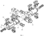
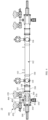
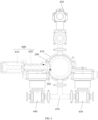
- an automatic cleaning system 10 based on a cleaning ball 300 comprises a delivery pipe 100, connecting pipes 200, a cleaning ball 300, a controller (not shown), two bypass pipe groups 400 and two stop mechanisms 500.
- the delivery pipe 100 is provided with a delivery channel 102, a feed inlet 104, a discharge outlet 106 and two connecting ports 108.
- the feed inlet 104, the discharge outlet 106 and the two connecting ports 108 are all in communication with the delivery channel 102.
- the feed inlet 104 is configured to be connected to a discharge end of a delivery pump; the number of the connecting pipes 200 are two, and the two connecting pipes 200 are respectively a first connecting pipe and a second connecting pipe; and the connecting port 108 connected to the first connecting pipe is arranged close to the feed inlet 104, and the connecting port 108 connected to the second connecting pipe is arranged close to the discharge outlet 106.
- the two bypass pipe groups 400 are respectively a first bypass pipe group and a second bypass pipe group; the first bypass pipe group is connected to the first connecting pipe, such that the first bypass pipe group is connected to the connecting port 108 close to the feed inlet 104 by means of the first connecting pipe; and the second bypass group is connected to the second connecting pipe, such that the second bypass pipe group is connected to the connecting port 108 close to the discharge outlet 106 by means of the second connecting pipe.
- first in-place sensors 103 are arranged on an outer wall of the delivery channel 102 between the feed inlet 104 and the discharge outlet 106, and the connecting pipes 200 are provided with second in-place sensors 203.
- each bypass pipe group 400 comprises a central pipe 410, a cleaning liquid feed pipe 420, a compressed air source pipe 430, a slurry discharge pipe 440 and a sewage discharge pipe 450.
- the central pipe 410 is connected to the delivery pipe 100 by means of the corresponding connecting pipe 200.
- the central pipe 410 is provided with a cleaning chamber 412 and an air-liquid inlet 414 connected to the cleaning chamber 412.
- the cleaning chamber 412 is connected to the cleaning liquid feed pipe 420 and the compressed air source pipe 430 by means of the air-liquid inlet 414, the cleaning chamber 412 is also connected to the sewage discharge pipe 450 and the slurry discharge pipe 440.
- the cleaning liquid feed pipe 420 and the compressed air source pipe 430 are both located above the central pipe 410, and the slurry discharge pipe 440 and the sewage discharge pipe 450 are both located below the central pipe 410.
- the two stop mechanisms 500 are mounted on the central pipes 410 of the corresponding bypass pipe groups 400 respectively, and each stop mechanism 500 is used for pushing the cleaning ball 300 from the cleaning chamber 412 of the corresponding central pipe 410 into the corresponding connecting pipe 200.
- the cleaning ball 300 can be pushed by airflow to move through the first connecting pipe, the delivery channel 102 and the second connecting pipe and into the cleaning chamber 412 of the second bypass pipe group. Alternatively, every time the delivery channel 102 finishes slurry delivery, the cleaning ball 300 can be pushed to move from the first connecting pipe through the delivery channel 102, the second connecting pipe and back to the delivery channel 102 and finally return to the first connecting pipe again, such that reliable pipe cleaning is realized. It can be understood that the pipe cleaning frequency using the cleaning ball 300 may be set as needed. For example, every time the delivery channel 102 finishes slurry delivery, the cleaning ball 300 cleans the delivery channel 102 to prevent residual slurry from being caked in the delivery channel 102.
- the compressed air source pipe 430 of the second bypass pipe group works, the cleaning ball 300 slides from the first connecting pipe into the corresponding cleaning chamber 412, at this moment, the driving shaft of the stop mechanism 500 on the central pipe 410 of the first bypass pipe group extends out by half of the maximum length, such that a major portion of the cleaning ball 300 is exposed in the cleaning chamber 412 and the cleaning ball 300 abuts against a power output end of the driving shaft of the stop mechanism 500, and the remaining portion of the cleaning ball 300 is located in the corresponding connecting pipe 200 to isolate the cleaning chamber 412 from the delivery channel 102; at this moment, the on-off control valve of the cleaning liquid feed pipe 420 of the first bypass pipe group is opened, the on-off control valve of the compressed air source pipe 430 of the first bypass pipe group is closed, the on-off control valve of the slurry discharge pipe 440 of the first bypass pipe group is closed, and the on-off control valve of the sewage discharge pipe
- the cleaning ball 300 moves into the cleaning chamber 412 of the first bypass pipe group under the action of airflow from the compressed air source pipe 430 of the second bypass pipe group, at this moment, the power output end of the stop mechanism 500 in the corresponding cleaning chamber 412 has a minimum travel distance
- the third in-place sensor 403 and the fourth in-place sensor 405 in the cleaning chamber 412 of the first bypass pipe group both sense the cleaning ball 300
- the cleaning chamber 412 of the first bypass pipe group is connected to the delivery channel 102 by means of the corresponding connecting pipe 200
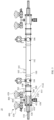
- the on-off control valve of the cleaning liquid feed pipe 420 close to the feed inlet 104 is opened, such that the portion of the cleaning ball 300, which is received in the connecting pipe 200 as shown in FIG.
- Cleaning liquid can flow from the cleaning camber 412 to the delivery channel 102 via the connecting pipe 200, and the cleaning ball 300 can be driven to move from the cleaning camber 412 of the first bypass pipe group to the delivery channel 102 and slide in the delivery channel 102 to thereby clean the delivery channel 102.
- the on-off control valve of the cleaning liquid feed pipe 420 close to the feed inlet 104 is opened.
- the cleaning ball 300 moves in the delivery channel 102 and the cleaning chambers 412 of the central pipes 410 of the two bypass pipe groups 400, and the first in-place sensors 103, the second in-place sensors 203, the third in-place sensors 403 and the fourth in-place sensors 405 work together for sensing, such that the controller, when receiving different signals, can control the on-off control valves of the cleaning liquid feed pipes 420, the on-off control valves of the compressed air source pipes 430 and the on-off control valves of the sewage discharge pipes 450 to act correspondingly to thereby achieve switching among the three models: delivering slurry, cleaning the cleaning ball 300, or cleaning both the delivery channel 102 and the cleaning ball 300. In this way, automatic delivery of slurry, automatic cleaning of the cleaning ball 300, and automatic cleaning of both the delivery channel 102 and the cleaning ball 300 are realized, manual intervention is reduced, and the labor intensity is relieved.
- a cleaning liquid inlet bypass pipe is added to a feed inlet 104 of a delivery pipe of a traditional cleaning system
- matching in size between the feed inlet 104 and the cleaning liquid inlet bypass pipe should be taken into account;
- one pipe is used for feeding both water and slurry, and the slurry is stored in a tank and pumped into the delivery pipe by a pump.
- cleaning liquid is first fed into the tank and then pumped into the delivery pipe by the pump, and the extra time spent in feeding cleaning liquid to the tank leads to low cleaning efficiency, particularly in a case where the pipeline has a large size.
- the cleaning liquid feed pipes 420 are arranged on the two bypass pipe groups 400 of the automatic cleaning system 10 based on the cleaning ball 300 provided by the application and work together with the controller, the first in-place sensors 103, the second in-place sensors 203, the third in-place sensors 403 and the fourth in-place sensors 405, thus improving the cleaning efficiency of the pipeline and making it possible to reduce water consumption.
- first connecting pipe and the second connecting pipe are symmetrically arranged at two ends of the delivery pipe 100
- first bypass pipe group and the second bypass pipe group are symmetrically arranged at the two ends of the delivery pipe 100.
- Each connecting pipe 200 is provided with a second in-place sensor 203
- the central pipe 410 of each bypass pipe group 400 is provided with a third in-place sensor 403 and a fourth in-place sensor 405.
- the automatic cleaning system 10 based on the cleaning ball 300 realizes synchronous cleaning of the cleaning ball 300 and the delivery pipe, that is, the automatic cleaning system 10 based on the cleaning ball 300 is a cleaning in place (CIP) system.
- CIP cleaning in place
- each bypass pipe group 400 further comprises an upper tee 460, wherein the cleaning chamber 412 is connected to a first end of the upper tee 460 by means of the air-liquid inlet 414, a second end of the upper tee 460 is connected to the cleaning liquid feed pipe 420, and a third end of the upper tee 460 is connected to the compressed air source pipe 430, such that the cleaning chamber 412 is in fluid communication with the compressed air source pipe 430 and the cleaning liquid feed pipe 420 by means of the air-liquid inlet 414 and the upper tee 460.
- the air-liquid inlet 414, the compressed air source pipe 430 and the cleaning liquid feed pipe 420 are connected to the ends of the upper tee 460 by means of locking and sealing elements respectively.
- each bypass pipe group 400 further comprises a lower tee 470, wherein the central pipe 410 is further provided with an air-liquid outlet 415, the cleaning chamber 412 is connected to a first end of the lower tee 470 by means of the air-liquid outlet 415, a second end of the lower tee 470 is connected to the slurry discharge pipe 440, and a third end of the lower tee 470 is connected to the sewage discharge pipe 450, such that the cleaning chamber 412 is in fluid communication with the slurry discharge pipe 440 and the sewage discharge pipe 450 by means of the air-liquid outlet 415 and the lower tee 470.
- the cleaning chamber 412 with the air-liquid outlet 415, the slurry discharge pipe 440 and the sewage discharge pipe 450 are connected to the ends of the lower tee 470 by means of locking and sealing elements respectively.
- an air pressure control valve is arranged at the discharge outlet 106, and the controller is electrically connected to a control end of the air pressure control valve to control the discharge outlet 106 to be opened or closed as needed. For example, after the cleaning ball 300 is pushed out from the cleaning chamber 412 of the first bypass pipe group by the airflow from the compressed air source pipe 430 and/or the stop pushrod 520 of the first bypass pipe group, the cleaning ball 300 can be further pushed to move in the delivery channel 102 by the airflow from the compressed air source pipe 430.
- the compressed air source pipe 430 of the first bypass pipe group is closed and the air pressure control valve and the on-off control valve of the slurry discharge pipe 440 of the second bypass pipe group are opened such that the air pressure for pushing the cleaning ball 300 moving in the delivery channel 102 is released via the discharge outlet 106 which results in the cleaning ball 300 slowing down and stopping in front of the cleaning chamber 412 of the second bypass pipe.
- the compressed air source pipe 430 of the first bypass pipe group is opened again and the airflow coming from the compressed air source pipe 430 of the first bypass pipe group pushes the cleaning ball 300 to enter into the cleaning chamber 412 of the second bypass pipe group.
- the cleaning ball 300 can be pushed into the cleaning chamber 412 of the second bypass pipe group with a relatively small speed/kinetic energy, a violent collision of the cleaning ball 300 with other components in the cleaning chamber 412 is avoided and collision damage of the cleaning ball 300 is avoided.
- a pressure sensor 105 is arranged on the inner wall of the delivery channel 102 between the feed inlet 104 and the discharge outlet 106 and used for detecting the pressure in the delivery channel 102, and the controller is electrically connected to the pressure sensor 105.
- the air pressure control valve is closed; otherwise, the air pressure control valve is opened, which facilitates to prevent collision damage of the cleaning ball 300.
- the preset pressure may be calculated according to the sliding speed or other parameters of the cleaning ball 300 at the feed inlet 104 or the discharge outlet 106, and then, the speed and the displacement value of the cleaning ball 300 sliding into the cleaning chamber 412 under the condition that the on-off control valve of the slurry discharge pipe 440 of the second bypass pipe group is opened, are calculated.
- each stop mechanism 500 comprises a stop cylinder 510 and a stop pushrod 520.
- the central pipe 410 of each bypass pipe group 400 is provided with a mounting hole 413 in fluid communication with the cleaning chamber 412, the stop cylinder 510 of each stop mechanism 500 is mounted in the mounting hole 413 of the central pipe 410 of the corresponding bypass pipe group 400, and the stop pushrod 520 is connected to the driving shaft of the stop cylinder 510 of the corresponding stop mechanism 500, such that the stop cylinder 510 can drive the stop pushrod 520 to move.
- the stop cylinder 510 of each stop mechanism 500 is provided with a first travel sensor and a second travel sensor, and the first travel sensor and the second travel sensor are both electrically connected to the controller.
- the first travel sensor is triggered and generates a signal
- the stop cylinder 510 drives the stop pushrod 520 to move by half of a maximum distance, that is, the driving shaft of the stop mechanism 500 on the central pipe 410 of the first bypass pipe group extends out by half of the maximum length
- the second travel sensor is triggered and generates a signal.
- a ball cage 4122 is arranged in the cleaning chamber 412, an opening of the ball cage 4122 is in fluid communication with the corresponding connecting pipe 200, and an inner wall of the ball cage 4122 is in interference fit with the cleaning ball 300 when the cleaning ball 300 slides into the ball cage 4122, such that the cleaning ball 300 can be decelerated when sliding into the ball cage 4122.
- the air pressure control valve and the on-off control valve of the slurry discharge pipe 440 of the second bypass pipe group are opened, and the pressure for pushing the ball to move in the delivery channel 102 is completely released via the discharge outlet 106, such that the cleaning ball 300 stops in front of the cleaning chamber 412 of the central pipe 410 of the second bypass pipe group. In this way, a collision of the ball is avoided.
- the cleaning ball 300 moves into the cleaning chamber 412 by a short distance under inertia, and the cleaning ball 300 is decelerated when sliding into the ball cage 4122, which facilitates to better avoid the issue of cleaning ball 300 being damaged due to collisions.
- the air pressure control valve and the on-off control valve of the slurry discharge pipe 440 of the second bypass pipe group are opened; and when the cleaning ball 300 moves close to the discharge outlet 106, the air pressure control valve is closed, the cleaning ball 300 directly rushes into the cleaning chamber 412 without being stopped and started again, and the cleaning ball 300 is decelerated when sliding into the ball cage 4122, which facilitates to better avoid the issue of cleaning ball 300 being damaged due to collisions.
- the automatic cleaning system 10 based on the cleaning ball 300 further comprises two lock mechanisms 600.
- Each lock mechanism 600 comprises a lock cylinder 610 and a blocking rod 620, the lock cylinder 610 of each lock mechanism 600 is mounted on a peripheral wall of the corresponding connecting pipe 200, a drive shaft of the lock cylinder 610 of each lock mechanism 600 is connected to the corresponding blocking rod 620, a control end of the lock cylinder 610 of each lock mechanism 600 is in communication connection with the corresponding second in-place sensor 203.
- a limit hole 205 is formed in the peripheral wall of each connecting pipe 200, and when the corresponding second in-place sensor 202 sends out a sensing signal, the lock cylinder 610 of each lock mechanism 600 drives the corresponding blocking rod 620 to slide along the corresponding limit hole 205 into the corresponding connecting pipe 200 to abut against a recessed portion of the cleaning ball 300.
- the cleaning ball 300 stays in the connecting pipe 200 adjacent to the feed inlet 104, that is, when the cleaning ball 300 stays in the first connecting pipe, the cleaning ball 300 is sealed in the first connecting pipe, materials are delivered in the delivery channel 102, and the cleaning ball 300 is reliably retained in the first connecting pipe.
- the limit hole 205 is a step hole.
- a sliding distance of the cleaning ball 300 in the ball cage 4122 is greater than the maximum length of the cleaning ball 300, that is, the cleaning chamber 412 is lengthened, such that the cleaning ball 300 can be better buffered when sliding into to the ball cage 4122, which facilitates to better avoid the issue of cleaning ball 300 being damaged due to collisions.
- the cleaning chamber 412 and the delivery channel 102 need to be isolated by the cleaning ball 300, the cleaning ball 300 is pushed into the first connecting pipe by the stop cylinder 510, and then the compressed air source pipe 430 connected to the cleaning chamber 412 is opened to maintain an air pressure in the cleaning chamber 412, such that the cleaning ball 300 will be clamped in the pipe between the cleaning chamber 412 and the blocking rod 620 to fulfill a sealing effect.
- the cleaning chamber 412 can be isolated from the delivery channel 102 to prevent the slurry from being accumulated in the cleaning chamber 412 at the end close to the feed inlet 104.
- water is fed and discharged by means of bypass pipes on the cleaning chambers 412. Since the cleaning chambers 412 are not affected by other devices used for delivering slurry, the bypass pipes can be easily arranged on the cleaning chambers 412 by means of quick tees.
- the on-off control valves of the cleaning liquid feed pipes 420, the on-off control valves of the compressed air source pipes 430, the on-off control valves of the slurry discharge pipes 440 and the on-off control valves of the sewage discharge pipes 450 are all air valves.
- the controller is a microprogrammed control unit or an industrial computer.
- the automatic cleaning system 10 based on the cleaning ball 300 can realize comprehensive cleaning of equipment without prolonging the cleaning time, adding round trips of the cleaning ball and leading to a waste of cleaning liquid; and compared with a pushball system that realize comprehensive cleaning like a CIP system, but cannot prevent ball collisions on the market, the automatic cleaning system 10 provided by the application can prevent ball collisions and will not increase energy consumption and working complexity in cleaning.
- the cleaning ball 300 comprises a first ball body 310 and a second ball body 320 which are connected, wherein an annular groove 302 is formed in a joint between the first ball body 310 and the second ball body 320.
- An end, away from the second ball body 320, of the first ball body 310 is embedded with a first magnetic strip 312
- an end, away from the first ball body 310, of the second ball body 320 is embedded with a second magnetic strip 322
- an included angle is formed between an extension direction of the first magnetic strip 312 and an extension direction of the second magnetic strip 322, such that an improved magnetic field can be generated on the surface of the cleaning ball 300, and an improved detection effect in the cleaning chamber 412 can be realized by the cleaning ball 300.
- the included angle is equal to 90°.
Landscapes
- Engineering & Computer Science (AREA)
- Mechanical Engineering (AREA)
- Physics & Mathematics (AREA)
- Fluid Mechanics (AREA)
- Chemical & Material Sciences (AREA)
- General Physics & Mathematics (AREA)
- Chemical Kinetics & Catalysis (AREA)
- General Chemical & Material Sciences (AREA)
- Cleaning In General (AREA)
- General Engineering & Computer Science (AREA)
- Combustion & Propulsion (AREA)
Applications Claiming Priority (1)
| Application Number | Priority Date | Filing Date | Title |
|---|---|---|---|
| CN202311851982.0A CN117884440B (zh) | 2023-12-28 | 2023-12-28 | 基于清洗球的自动清洗系统 |
Publications (2)
| Publication Number | Publication Date |
|---|---|
| EP4578562A1 true EP4578562A1 (fr) | 2025-07-02 |
| EP4578562B1 EP4578562B1 (fr) | 2026-05-13 |
Family
ID=90643602
Family Applications (1)
| Application Number | Title | Priority Date | Filing Date |
|---|---|---|---|
| EP24223327.8A Active EP4578562B1 (fr) | 2023-12-28 | 2024-12-26 | Système de nettoyage automatique basé sur une balle de nettoyage |
Country Status (3)
| Country | Link |
|---|---|
| EP (1) | EP4578562B1 (fr) |
| KR (1) | KR20250103435A (fr) |
| CN (1) | CN117884440B (fr) |
Cited By (1)
| Publication number | Priority date | Publication date | Assignee | Title |
|---|---|---|---|---|
| CN121491100A (zh) * | 2026-01-09 | 2026-02-10 | 宁德致恒智能机械有限公司 | 一种基于自动往复推球机构的管道清洁装置 |
Citations (3)
| Publication number | Priority date | Publication date | Assignee | Title |
|---|---|---|---|---|
| CN207012917U (zh) * | 2017-02-17 | 2018-02-16 | 无锡唯勒科技有限公司 | 锂电池浆料输送系统 |
| CN216880877U (zh) * | 2022-03-17 | 2022-07-05 | 广东奥瑞特新能源设备科技有限公司 | 一种管道清扫球的自动收发清洁器 |
| CN219965865U (zh) | 2023-06-29 | 2023-11-07 | 河南福森新能源科技有限公司 | 电极浆料输送管道清洁装置 |
Family Cites Families (4)
| Publication number | Priority date | Publication date | Assignee | Title |
|---|---|---|---|---|
| KR101280508B1 (ko) * | 2011-04-06 | 2013-07-01 | 설원실 | 세정볼을 이용한 판형 열교환기 자동오염제거장치 |
| CN209772972U (zh) * | 2019-03-20 | 2019-12-13 | 广东智子智能技术有限公司 | 一种管道清洗系统 |
| CN217432509U (zh) * | 2022-01-28 | 2022-09-16 | 广东美味鲜调味食品有限公司 | 可预存清洗球的管道装置 |
| CN218340559U (zh) * | 2022-09-13 | 2023-01-20 | 上海卡沃生物工程技术有限公司 | 一种新型清洗系统 |
-
2023
- 2023-12-28 CN CN202311851982.0A patent/CN117884440B/zh active Active
-
2024
- 2024-11-27 KR KR1020240171770A patent/KR20250103435A/ko active Pending
- 2024-12-26 EP EP24223327.8A patent/EP4578562B1/fr active Active
Patent Citations (3)
| Publication number | Priority date | Publication date | Assignee | Title |
|---|---|---|---|---|
| CN207012917U (zh) * | 2017-02-17 | 2018-02-16 | 无锡唯勒科技有限公司 | 锂电池浆料输送系统 |
| CN216880877U (zh) * | 2022-03-17 | 2022-07-05 | 广东奥瑞特新能源设备科技有限公司 | 一种管道清扫球的自动收发清洁器 |
| CN219965865U (zh) | 2023-06-29 | 2023-11-07 | 河南福森新能源科技有限公司 | 电极浆料输送管道清洁装置 |
Cited By (1)
| Publication number | Priority date | Publication date | Assignee | Title |
|---|---|---|---|---|
| CN121491100A (zh) * | 2026-01-09 | 2026-02-10 | 宁德致恒智能机械有限公司 | 一种基于自动往复推球机构的管道清洁装置 |
Also Published As
| Publication number | Publication date |
|---|---|
| EP4578562B1 (fr) | 2026-05-13 |
| CN117884440B (zh) | 2024-09-24 |
| CN117884440A (zh) | 2024-04-16 |
| KR20250103435A (ko) | 2025-07-07 |
Similar Documents
| Publication | Publication Date | Title |
|---|---|---|
| EP4578562B1 (fr) | Système de nettoyage automatique basé sur une balle de nettoyage | |
| JP6546298B2 (ja) | ポンプ用のランナウェイバルブシステム | |
| JP6534535B2 (ja) | 給水システム | |
| CN208793040U (zh) | 一种适用于隧道区间低洼点的分散式真空排水系统 | |
| EP1536135A2 (fr) | Une pompe | |
| CA2698910C (fr) | Systeme de pompes multiples a fonctionnement decale | |
| CN102410188B (zh) | 闸板式混凝土泵及其泵送控制系统 | |
| CN103075328A (zh) | 水动隔膜泵 | |
| CN216894772U (zh) | 泵送装置和浆料输送设备 | |
| CN107476860B (zh) | 一种尿素溶液供给系统 | |
| EP0126608A1 (fr) | Dispositifs à fluide | |
| CN113731965B (zh) | 用于对车辆液压制动系统处理的设备 | |
| JP6093989B1 (ja) | スラリー移送システム、及び、タンクユニット | |
| CN108730551B (zh) | 一种三通阀 | |
| CN213574890U (zh) | 一种多泵全自动注射泵 | |
| CN1266011C (zh) | 浆料输送设备 | |
| KR101631030B1 (ko) | 고압토출이 가능한 물이송장치 | |
| CN216429856U (zh) | 一种双向运动的活塞泵 | |
| CN109989900B (zh) | 糊状物料输送装置及其控制方法和工程车辆 | |
| CN109058525A (zh) | 一种可泵送压缩性物料的单出口流线型阀体装置 | |
| CN102430533B (zh) | 一种工程机械及其水洗系统 | |
| CN210317637U (zh) | 高精度流量控制系统 | |
| CN210440173U (zh) | 糊状物料输送装置和工程车辆 | |
| CN205289150U (zh) | 节能泵自动清洗装置 | |
| CN217492015U (zh) | 一种可回收管内物料的回收装置 |
Legal Events
| Date | Code | Title | Description |
|---|---|---|---|
| PUAI | Public reference made under article 153(3) epc to a published international application that has entered the european phase |
Free format text: ORIGINAL CODE: 0009012 |
|
| STAA | Information on the status of an ep patent application or granted ep patent |
Free format text: STATUS: THE APPLICATION HAS BEEN PUBLISHED |
|
| AK | Designated contracting states |
Kind code of ref document: A1 Designated state(s): AL AT BE BG CH CY CZ DE DK EE ES FI FR GB GR HR HU IE IS IT LI LT LU LV MC ME MK MT NL NO PL PT RO RS SE SI SK SM TR |
|
| STAA | Information on the status of an ep patent application or granted ep patent |
Free format text: STATUS: REQUEST FOR EXAMINATION WAS MADE |
|
| 17P | Request for examination filed |
Effective date: 20250722 |
|
| GRAP | Despatch of communication of intention to grant a patent |
Free format text: ORIGINAL CODE: EPIDOSNIGR1 |
|
| STAA | Information on the status of an ep patent application or granted ep patent |
Free format text: STATUS: GRANT OF PATENT IS INTENDED |
|
| RIC1 | Information provided on ipc code assigned before grant |
Ipc: B08B 9/057 20060101AFI20251031BHEP Ipc: B08B 9/032 20060101ALI20251031BHEP |
|
| INTG | Intention to grant announced |
Effective date: 20251201 |
|
| GRAS | Grant fee paid |
Free format text: ORIGINAL CODE: EPIDOSNIGR3 |
|
| GRAA | (expected) grant |
Free format text: ORIGINAL CODE: 0009210 |
|
| STAA | Information on the status of an ep patent application or granted ep patent |
Free format text: STATUS: THE PATENT HAS BEEN GRANTED |
|
| AK | Designated contracting states |
Kind code of ref document: B1 Designated state(s): AL AT BE BG CH CY CZ DE DK EE ES FI FR GB GR HR HU IE IS IT LI LT LU LV MC ME MK MT NL NO PL PT RO RS SE SI SK SM TR |
|
| REG | Reference to a national code |
Ref country code: CH Ref legal event code: F10 Free format text: ST27 STATUS EVENT CODE: U-0-0-F10-F00 (AS PROVIDED BY THE NATIONAL OFFICE) Effective date: 20260513 |