EP4578584A1 - Joint soudé par points et son procédé de fabrication - Google Patents
Joint soudé par points et son procédé de fabrication Download PDFInfo
- Publication number
- EP4578584A1 EP4578584A1 EP23856553.5A EP23856553A EP4578584A1 EP 4578584 A1 EP4578584 A1 EP 4578584A1 EP 23856553 A EP23856553 A EP 23856553A EP 4578584 A1 EP4578584 A1 EP 4578584A1
- Authority
- EP
- European Patent Office
- Prior art keywords
- spot
- welding
- workpiece
- welded joint
- stage
- Prior art date
- Legal status (The legal status is an assumption and is not a legal conclusion. Google has not performed a legal analysis and makes no representation as to the accuracy of the status listed.)
- Pending
Links
Images




Classifications
-
- B—PERFORMING OPERATIONS; TRANSPORTING
- B23—MACHINE TOOLS; METAL-WORKING NOT OTHERWISE PROVIDED FOR
- B23K—SOLDERING OR UNSOLDERING; WELDING; CLADDING OR PLATING BY SOLDERING OR WELDING; CUTTING BY APPLYING HEAT LOCALLY, e.g. FLAME CUTTING; WORKING BY LASER BEAM
- B23K11/00—Resistance welding; Severing by resistance heating
- B23K11/30—Features relating to electrodes
- B23K11/31—Electrode holders and actuating devices therefor
-
- B—PERFORMING OPERATIONS; TRANSPORTING
- B23—MACHINE TOOLS; METAL-WORKING NOT OTHERWISE PROVIDED FOR
- B23K—SOLDERING OR UNSOLDERING; WELDING; CLADDING OR PLATING BY SOLDERING OR WELDING; CUTTING BY APPLYING HEAT LOCALLY, e.g. FLAME CUTTING; WORKING BY LASER BEAM
- B23K11/00—Resistance welding; Severing by resistance heating
- B23K11/10—Spot welding; Stitch welding
- B23K11/11—Spot welding
-
- B—PERFORMING OPERATIONS; TRANSPORTING
- B23—MACHINE TOOLS; METAL-WORKING NOT OTHERWISE PROVIDED FOR
- B23K—SOLDERING OR UNSOLDERING; WELDING; CLADDING OR PLATING BY SOLDERING OR WELDING; CUTTING BY APPLYING HEAT LOCALLY, e.g. FLAME CUTTING; WORKING BY LASER BEAM
- B23K11/00—Resistance welding; Severing by resistance heating
- B23K11/10—Spot welding; Stitch welding
- B23K11/11—Spot welding
- B23K11/115—Spot welding by means of two electrodes placed opposite one another on both sides of the welded parts
-
- B—PERFORMING OPERATIONS; TRANSPORTING
- B23—MACHINE TOOLS; METAL-WORKING NOT OTHERWISE PROVIDED FOR
- B23K—SOLDERING OR UNSOLDERING; WELDING; CLADDING OR PLATING BY SOLDERING OR WELDING; CUTTING BY APPLYING HEAT LOCALLY, e.g. FLAME CUTTING; WORKING BY LASER BEAM
- B23K11/00—Resistance welding; Severing by resistance heating
- B23K11/30—Features relating to electrodes
-
- B—PERFORMING OPERATIONS; TRANSPORTING
- B23—MACHINE TOOLS; METAL-WORKING NOT OTHERWISE PROVIDED FOR
- B23K—SOLDERING OR UNSOLDERING; WELDING; CLADDING OR PLATING BY SOLDERING OR WELDING; CUTTING BY APPLYING HEAT LOCALLY, e.g. FLAME CUTTING; WORKING BY LASER BEAM
- B23K11/00—Resistance welding; Severing by resistance heating
- B23K11/36—Auxiliary equipment
-
- B—PERFORMING OPERATIONS; TRANSPORTING
- B23—MACHINE TOOLS; METAL-WORKING NOT OTHERWISE PROVIDED FOR
- B23K—SOLDERING OR UNSOLDERING; WELDING; CLADDING OR PLATING BY SOLDERING OR WELDING; CUTTING BY APPLYING HEAT LOCALLY, e.g. FLAME CUTTING; WORKING BY LASER BEAM
- B23K2101/00—Articles made by soldering, welding or cutting
- B23K2101/006—Vehicles
Definitions
- the present invention relates to the field of resistance spot welding, and more specifically, to a spot-welded joint formed by resistance spot welding of two or more layers of metal workpieces (especially aluminum alloy workpieces) and its manufacturing method.
- Riveting is a way that is costly, complicated, has poor surface quality, and increases the weight of the vehicle body.
- a full aluminum or hybrid vehicle body usually requires more than 1,500 nails.
- Resistance spot welding uses the heat generated by the resistance of the workpiece itself and between them to melt the material and achieve connection. Since it does not require filling materials during the connection process, has high production efficiency and is easy to automate, this method is widely used in vehicle body manufacturing, such as engine hood, doors, etc. With the application of aluminum alloys in automobiles, automobile manufacturers expect to continue using resistance spot welding to connect aluminum alloys.
- Patent CN104043898A discloses a method of using multiple raised annular ridges on a spherical electrode to puncture the surface oxide film, improve electrode life and surface quality.
- this method is prone to form crackss on the surface of the welded joint due to the fact that welding heat is still mainly concentrated in the center of the welded joint, leading to a decrease in welded joint strength.
- Patent US6646221B2 discloses a method for secondary repair welding of aluminum spot welding.
- a circular concave cavity electrode is used to re-weld on the outside to expand the weld nugget size.
- this method can make the final weld nugget quality satisfy the standard, it is a method for existing welded joints with small weld nuggets, which requires multiple implementations and cannot suppress the elimination of internal defects and surface cracks in the welded joints. Moreover, the electrode life is lower.
- the purpose of the present invention is to provide a resistance spot-welded joint and a manufacturing method therefor, so as to obtain a spot-welded joint with higher weld strength and fewer welding defects, and to solve the problems of spatter, serious defects, low welding strength, unstable welding quality, and low electrode life in aluminum alloy resistance spot welding in the prior art.
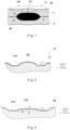
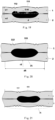
- a spot-welded joint comprising a first workpiece, a second workpiece, and a weld nugget configured for fixedly connecting the first workpiece and the second workpiece; at least one of an outer surface of the first workpiece and an outer surface of the second workpiece comprising a base surface and an indentation; wherein the indentation comprises a first surface which is located in the center and protrudes outwards and a second surface which is located on the periphery of the first surface and recessed inwardly, and the maximum distance hl between the first surface and the base surface is smaller than the maximum distance h2 between the second surface and the base surface.
- the first surface and/or the second surface have multiple discontinuous distributed protruding or recessed annular ridges; and a height of the annular ridge is 15-300 ⁇ m.
- the weld nugget is in the shape of a circular pancake with a thin center and a thick periphery.
- a longest distance s1 between a thinner area in middle of the weld nugget and the first surface of the workpiece, and a shortest distance s2 between a thicker area at peripheral and the second surface satisfy: 0.2 ⁇ s 1 ⁇ w ⁇ 0.8 w ; s2 ⁇ 0.9w; s1 ⁇ s2, preferably s1 ⁇ 1.2*s2, where w is a thickness of the workpiece.
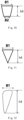
- first surface and/or the second surface are composed of a combination of multiple continuous flat surfaces and curved surfaces.
- the spot-welded joint is a centrally symmetrical structure.
- a pair of spot welding electrode caps are provided, which are configured for welding to obtain the above-mentioned spot-welded joint, wherein welding surfaces of the spot welding electrode caps have shapes adapted to outer surfaces of the first workpiece and the second workpiece, respectively.
- the welding stage comprises a pre-heating stage, a main welding stage, and a post-heating stage; an effective value of a welding current I1 during the pre-heating stage is 10-30KA, and an energization time t1 is 30-60ms; an effective value of a welding current I2 during the main welding stage is 20-60KA, and a total energization time t2 is 50-300ms; a welding current I3 during the post-heating stage is 15-40KA, and an energization time t3 is 20-100ms.
- the weld nugget is formed by multiple identical or different current pulses, each welding current is 25-50KA, a duration of a single welding pulse is 5-30ms, a pulse interval time is 1-10ms; a number of pulses is at least 3; and a pulse interval cooling time is 1-10ms.
- the inventors have conducted extensive and in-depth research and developed a spot-welded joint and a manufacturing method therefor for the first time after extensive screening.
- the spot-welded joint of the present invention forms a round pancake-shaped weld nugget which is thin in the center and thick on the periphery through an indentation including a first surface convex outwardly located at the center and a second surface concave inwardly located on the periphery of the first surface, so that the spot-welded joint has better surface quality and welding performance, and higher joint strength.
- the spot-welded joint of the present invention can form a weld nugget by multi-stage welding with multi-segment pulse and inter-stage cooling, so that the formed weld nugget is more stable and requires less welding energy.
- the present invention is completed on this basis.
- the present invention provides a spot-welded joint, which has a central symmetrical structure as a whole. When viewed along the cross-section of the joint, the joint comprises a melted zone and an unmelted zone.
- the spot-welded joint has a bonding interface and opposite upper and lower surfaces. The outer surfaces of the workpieces in the weld spot region have indentations generally away from the melted zones of the workpieces.
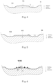
- At least one side indentation comprises at least a first surface at the center and a second surface gradually extending outward.
- the maximum distance h1 between the first surface at the center of the indentation and the outer surface of the workpiece is lower than the maximum distance h2 between the second surface outside the center indentation and the workpiece surface.
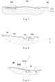
- the diameter of the outer circumference of the base surface 1122 is d3, generally 7-13mm, preferably 8-12mm.
- the outer surface 1121 can be a conical or curved surface. When the outer surface 1121 is a conical surface, the angle formed between it and the workpiece surface 10 is generally ⁇ , and ⁇ does not exceed 40°, preferably 5° ⁇ 30°, as shown in Fig. 8 .
- the outer surface 1121 can also be a curved surface as a whole. When it is a curved surface, its radius r1 of the curved surface is not less than 20mm, preferably 25 ⁇ r1 ⁇ 100mm.
Landscapes
- Engineering & Computer Science (AREA)
- Mechanical Engineering (AREA)
- Resistance Welding (AREA)
Applications Claiming Priority (2)
| Application Number | Priority Date | Filing Date | Title |
|---|---|---|---|
| CN202211007511.7A CN115255587B (zh) | 2022-08-22 | 2022-08-22 | 点焊接头及其制造方法 |
| PCT/CN2023/113830 WO2024041463A1 (fr) | 2022-08-22 | 2023-08-18 | Joint soudé par points et son procédé de fabrication |
Publications (1)
| Publication Number | Publication Date |
|---|---|
| EP4578584A1 true EP4578584A1 (fr) | 2025-07-02 |
Family
ID=83752210
Family Applications (1)
| Application Number | Title | Priority Date | Filing Date |
|---|---|---|---|
| EP23856553.5A Pending EP4578584A1 (fr) | 2022-08-22 | 2023-08-18 | Joint soudé par points et son procédé de fabrication |
Country Status (4)
| Country | Link |
|---|---|
| EP (1) | EP4578584A1 (fr) |
| JP (1) | JP2025526987A (fr) |
| CN (1) | CN115255587B (fr) |
| WO (1) | WO2024041463A1 (fr) |
Families Citing this family (3)
| Publication number | Priority date | Publication date | Assignee | Title |
|---|---|---|---|---|
| CN115255587B (zh) * | 2022-08-22 | 2025-10-31 | 中国科学院上海光学精密机械研究所 | 点焊接头及其制造方法 |
| CN116213903B (zh) * | 2023-02-24 | 2026-01-02 | 中国科学院上海光学精密机械研究所 | 用于铝工件胶接点焊的电极帽及其焊接方法 |
| CN116197509B (zh) * | 2023-02-24 | 2026-01-02 | 中国科学院上海光学精密机械研究所 | 用于铝工件电阻点焊的电极帽及点焊方法 |
Family Cites Families (21)
| Publication number | Priority date | Publication date | Assignee | Title |
|---|---|---|---|---|
| JP3120933B2 (ja) * | 1993-11-29 | 2000-12-25 | トヨタ自動車株式会社 | 抵抗溶接制御方法 |
| US6646221B2 (en) * | 2002-04-15 | 2003-11-11 | General Motors Corporation | Method for repairing resistance spot welds in aluminum sheet materials |
| WO2007055130A1 (fr) * | 2005-11-09 | 2007-05-18 | Daihatsu Motor Co., Ltd. | Procede de soudage par points, procede d'evaluation de la forme des lentilles de soudure, machines de soudage par points et electrode de soudage par points |
| JP4724535B2 (ja) * | 2005-11-14 | 2011-07-13 | 新日本製鐵株式会社 | 高強度鋼板スポット溶接継手の疲労強度向上方法 |
| JP5187806B2 (ja) * | 2006-10-12 | 2013-04-24 | ダイハツ工業株式会社 | 抵抗スポット溶接方法 |
| DE102013224443A1 (de) | 2013-03-15 | 2014-09-18 | GM Global Technology Operations, LLC (n.d. Ges. d. Staates Delaware) | Schweissflächengestaltung zum Punktschweissen |
| CN104084686B (zh) * | 2014-06-12 | 2017-01-18 | 上海翼锐汽车科技有限公司 | 一种用于抑制铝合金电阻点焊裂纹产生的电极 |
| KR20160002450A (ko) * | 2014-06-30 | 2016-01-08 | 현대제철 주식회사 | 용접 장치 |
| JP6108018B2 (ja) * | 2015-09-03 | 2017-04-05 | 新日鐵住金株式会社 | スポット溶接方法 |
| CN105081545A (zh) * | 2015-09-15 | 2015-11-25 | 上海交通大学 | 电阻点焊焊核偏移控制装置及方法 |
| CN110369848B (zh) * | 2018-04-12 | 2022-09-02 | 中国科学院上海光学精密机械研究所 | 一种电阻点焊电极帽 |
| JP7155903B2 (ja) * | 2018-11-12 | 2022-10-19 | 日本製鉄株式会社 | 抵抗スポット溶接用電極および抵抗スポット溶接継手の製造方法 |
| CN112570867B (zh) * | 2019-09-27 | 2023-02-14 | 中国科学院上海光学精密机械研究所 | 一种抑制铝合金电阻点焊熔核内部缺陷产生的方法 |
| CN112916992A (zh) * | 2019-12-06 | 2021-06-08 | 中国科学院上海光学精密机械研究所 | 用于焊接高强度钢的电阻点焊电极及其焊接方法 |
| CN215658390U (zh) * | 2020-07-31 | 2022-01-28 | 中国科学院上海光学精密机械研究所 | 一种电阻点焊电极 |
| CN215658527U (zh) * | 2021-05-27 | 2022-01-28 | 中国科学院上海光学精密机械研究所 | 一种铝钢异种金属的焊接接头 |
| CN114101883B (zh) * | 2021-11-26 | 2023-06-02 | 中国科学院上海光学精密机械研究所 | 一种用于低熔点涂镀层钢工件的电阻点焊方法 |
| CN218592043U (zh) * | 2022-08-22 | 2023-03-10 | 中国科学院上海光学精密机械研究所 | 点焊接头及用于其的点焊电极帽 |
| CN115255587B (zh) * | 2022-08-22 | 2025-10-31 | 中国科学院上海光学精密机械研究所 | 点焊接头及其制造方法 |
| CN116197509B (zh) * | 2023-02-24 | 2026-01-02 | 中国科学院上海光学精密机械研究所 | 用于铝工件电阻点焊的电极帽及点焊方法 |
| CN116213903B (zh) * | 2023-02-24 | 2026-01-02 | 中国科学院上海光学精密机械研究所 | 用于铝工件胶接点焊的电极帽及其焊接方法 |
-
2022
- 2022-08-22 CN CN202211007511.7A patent/CN115255587B/zh active Active
-
2023
- 2023-08-18 JP JP2025511535A patent/JP2025526987A/ja active Pending
- 2023-08-18 EP EP23856553.5A patent/EP4578584A1/fr active Pending
- 2023-08-18 WO PCT/CN2023/113830 patent/WO2024041463A1/fr not_active Ceased
Also Published As
| Publication number | Publication date |
|---|---|
| CN115255587A (zh) | 2022-11-01 |
| JP2025526987A (ja) | 2025-08-15 |
| CN115255587B (zh) | 2025-10-31 |
| WO2024041463A1 (fr) | 2024-02-29 |
Similar Documents
| Publication | Publication Date | Title |
|---|---|---|
| EP4578584A1 (fr) | Joint soudé par points et son procédé de fabrication | |
| CN110369848B (zh) | 一种电阻点焊电极帽 | |
| CN218592043U (zh) | 点焊接头及用于其的点焊电极帽 | |
| CN112676688A (zh) | 一种异质金属电阻点焊方法 | |
| CN117691264A (zh) | 电池壳体、电池外壳及电池 | |
| CN116213903B (zh) | 用于铝工件胶接点焊的电极帽及其焊接方法 | |
| EP4607688A1 (fr) | Montant de borne, structure de couvercle supérieur, cellule de batterie, module de batterie et bloc-batterie | |
| CN1623048A (zh) | 同步设备的多元件同步环 | |
| CN221282336U (zh) | 一种一体化密封铝片、顶盖结构及电芯 | |
| CN116197509B (zh) | 用于铝工件电阻点焊的电极帽及点焊方法 | |
| CN111745275A (zh) | 一种电阻点焊电极帽及焊接方法 | |
| CN219358251U (zh) | 用于铝工件胶接点焊的电极帽 | |
| CN118268690A (zh) | 一种铝电阻点焊电极帽 | |
| CN220112537U (zh) | 用于铝工件电阻点焊的电极帽 | |
| CN115382991B (zh) | 一种低延展性金属材料的高强度无铆连接方法 | |
| JP6740929B2 (ja) | 陽極酸化処理用複合部材の製造方法及び陽極酸化処理用複合部材 | |
| CN215658390U (zh) | 一种电阻点焊电极 | |
| CN119057195A (zh) | 一种铝合金点焊装置及焊接方法 | |
| CN207921069U (zh) | 点焊铆钉 | |
| CN120533241B (zh) | 一种长寿命铝合金电阻焊用焊接电极及焊接方法 | |
| CN222154245U (zh) | 一种铝电阻点焊电极帽 | |
| CN100519227C (zh) | 汽车用整面车轮的制造方法 | |
| CN218341214U (zh) | 一种用于热成型钢电阻点焊的电极帽 | |
| CN212070759U (zh) | 一种用于电阻缝焊的电极轮 | |
| WO2020221362A1 (fr) | Outil de coupe et procédé d'entretien d'une électrode de soudage dotée d'une cuvette centrale |
Legal Events
| Date | Code | Title | Description |
|---|---|---|---|
| STAA | Information on the status of an ep patent application or granted ep patent |
Free format text: STATUS: THE INTERNATIONAL PUBLICATION HAS BEEN MADE |
|
| PUAI | Public reference made under article 153(3) epc to a published international application that has entered the european phase |
Free format text: ORIGINAL CODE: 0009012 |
|
| STAA | Information on the status of an ep patent application or granted ep patent |
Free format text: STATUS: REQUEST FOR EXAMINATION WAS MADE |
|
| 17P | Request for examination filed |
Effective date: 20250304 |
|
| AK | Designated contracting states |
Kind code of ref document: A1 Designated state(s): AL AT BE BG CH CY CZ DE DK EE ES FI FR GB GR HR HU IE IS IT LI LT LU LV MC ME MK MT NL NO PL PT RO RS SE SI SK SM TR |
|
| DAV | Request for validation of the european patent (deleted) | ||
| DAX | Request for extension of the european patent (deleted) |