EP4578662A1 - Equipement pour le montage, le démontage et le déplacement d'une roue d'un véhicule automobile. - Google Patents
Equipement pour le montage, le démontage et le déplacement d'une roue d'un véhicule automobile. Download PDFInfo
- Publication number
- EP4578662A1 EP4578662A1 EP24222085.3A EP24222085A EP4578662A1 EP 4578662 A1 EP4578662 A1 EP 4578662A1 EP 24222085 A EP24222085 A EP 24222085A EP 4578662 A1 EP4578662 A1 EP 4578662A1
- Authority
- EP
- European Patent Office
- Prior art keywords
- shaped portion
- tubulars
- gripping
- wheel
- equipment
- Prior art date
- Legal status (The legal status is an assumption and is not a legal conclusion. Google has not performed a legal analysis and makes no representation as to the accuracy of the status listed.)
- Pending
Links
Images


Classifications
-
- B—PERFORMING OPERATIONS; TRANSPORTING
- B60—VEHICLES IN GENERAL
- B60B—VEHICLE WHEELS; CASTORS; AXLES FOR WHEELS OR CASTORS; INCREASING WHEEL ADHESION
- B60B30/00—Means for holding wheels or parts thereof
- B60B30/02—Means for holding wheels or parts thereof engaging the tyre, e.g. the tyre being mounted on the wheel rim
-
- B—PERFORMING OPERATIONS; TRANSPORTING
- B60—VEHICLES IN GENERAL
- B60B—VEHICLE WHEELS; CASTORS; AXLES FOR WHEELS OR CASTORS; INCREASING WHEEL ADHESION
- B60B29/00—Apparatus or tools for mounting or dismounting wheels
- B60B29/001—Apparatus or tools for mounting or dismounting wheels comprising lifting or aligning means
-
- B—PERFORMING OPERATIONS; TRANSPORTING
- B60—VEHICLES IN GENERAL
- B60B—VEHICLE WHEELS; CASTORS; AXLES FOR WHEELS OR CASTORS; INCREASING WHEEL ADHESION
- B60B29/00—Apparatus or tools for mounting or dismounting wheels
- B60B29/003—Wrenches, e.g. of the ratchet type
- B60B29/006—Wrenches, e.g. of the ratchet type with electric or pneumatic drive
Definitions
- the present invention concerns an equipment for mounting, removing and moving a wheel of a motor vehicle.
- motor vehicle means herein a generic vehicle (car, bus, lorry, road train, etc.) powered by its own engine and having the energy source on board, with at least four wheels, capable of circulating on ordinary roads and equipped with devices for direction and braking.
- a component of the motor vehicle typically subject to routine maintenance is the tire.
- the tires are the contact component of the vehicle with the ground, which is consequently greatly influenced by the state of the ground, resulting in completely different conditions between the over 30°C in summer and even -20°C in winter.
- the tire change operation envisages the following steps for each tire:
- the movement operations are generally manual or at the most they make use of a carriage. Normally the wheel must be rotated through 90°, lying vertically when mounted and horizontally when placed on the ground or on a bench.
- Solutions for the mounting and removing a wheel which provide gripping devices that allow the wheel to be lifted and coupled to the axle of a motor vehicle, and vice versa.
- CA-1114856 describes a flag structure with a gripping head which however is not suitable for gripping a wheel, for example for changing tires in a mechanical workshop for the maintenance of a motor vehicle.
- WO-2022/204783 describes an equipment for mounting and removing a wheel on/from a motor vehicle and moving the wheel in a mechanical workshop.
- a further object of the present invention is that said equipment allows the mounting of the wheel on the axle of the motor vehicle, and vice versa, in a mechanical workshop for the maintenance of a motor vehicle.
- Yet another object of the present invention is that said equipment is not bulky, it is simple to manufacture and inexpensive.
- the equipment is made with inexpensive means available on the market, mostly tubular elements with pneumatic means, it adapts to the spaces of any mechanical workshop and allows for example a quick tire change with little effort by the operator who can perform hundreds of tire changes in a day, thus increasing the productivity of the workshop in terms of assistance, especially in the months of April and November when the need for tire changes is greater, from winter tires to summer tires or vice versa.
- the telescopic movement of the parallel tubulars makes it easy to pick up and release a wheel using a compact structure.
- An equipment 1 for mounting and removing a wheel on/from a motor vehicle and moving the wheel in a mechanical workshop comprises flag support means 2 and a gripping device 3 for a wheel, wherein wheel means the assembly of tire and rim.
- the flag support means 2 ( Figure 2 ) comprise a first arm 21 and a second arm 22 rotatably fixed to the first arm 21 which in turn is rotatably fixed to means integral with the ground, for example a column.
- the arms 21, 22 extend horizontally and the rotations of the second arm 22 with respect to the first arm 21, and of the first arm 21 with respect to the column, take place about a vertical axis.
- the second arm 22 is hinged to the first arm 21 so as to be able to rotate 360°, also below the first arm 21 which is longer than the second arm 22 so as not to interfere for example with the column during rotation with respect to the first arm 21.
- Figures 1 and 2 also show a hose 23 into which the air for the pneumatic means passes, which will be described below.
- the hinge between the first arm 21 and second arm 22 preferably allows the passage of said hose 23 so as not to hinder the mutual rotary movement.
- a rod 4 extends downwards, substantially vertically, which is part of a pneumatic piston 5 able to vary the height of a head 6 of the gripping device 3.
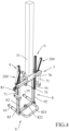
- the head 6 comprises a C-shaped support 7 ( Figure 4 ) composed of two tubulars 71, preferably with a round section, parallel to each other and integral with the ends of a connecting tubular 75 preferably with a square section.
- the connecting tubular 75 is fixed to a cylinder 51 of the pneumatic piston 5 by means of an L-shaped plate 76 so as to be orthogonal to the cylinder 51 of the pneumatic piston 5.
- the tubulars 71 extend downwards and also perform the function of handles for the operator and preferably as a support for control means (not shown) of pneumatic means such as for example the pneumatic piston 5.
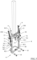
- the head 6 also comprises a parallelogram element 8 ( Figure 3 ) rotatably fixed by connection means 74 to the C-shaped support 7 at the lower ends 73 of the tubulars 71.
- connection means 74 preferably comprise a pair of tubulars 741 orthogonal to the tubulars 71 and attachment pins 742.
- the parallelogram element 8 can be rotated about a horizontal axis with respect to the C-shaped support 7 ( Figures 3-6 ).
- the parallelogram element 8 is composed of a first C-shaped portion 81 and a second C-shaped portion 82, wherein the first C-shaped portion 81 is rotatably fixed to the C-shaped support 7 via the connection means 74.
- the first C-shaped portion 81 comprises two parallel tubulars 811 and a connecting tubular 812 able to rigidly connect said two parallel tubulars 811.
- the second C-shaped portion 82 comprises two parallel tubulars 821 and a connecting tubular 822 able to rigidly connect said two parallel tubulars 821.
- the two parallel tubulars 821 of the second C-shaped portion 82 are able to be telescopically inserted into the two parallel tubulars 811 of the first C-shaped portion 81.
- Two pneumatic pistons 9 ( Figure 5 ) control the sliding of the second C-shaped portion 82 with respect to the first C-shaped portion 81.
- the pneumatic pistons 9 comprise cylinders 91 fixed to the parallel tubulars 811 of the first C-shaped portion 81, and rods 92, sliding in the cylinders 91, having an end 921 fixed to projections 823 of the parallel tubulars 821 of the second C-shaped portion 82.
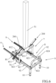
- a handle 824 preferably extends from the connecting tubular 822 of the second C-shaped portion 82 ( Figure 6 ), while, from the ends of the parallel tubulars 821 and of the connecting tubular 822, two gripping rollers 10 extend in an orthogonal direction with respect to the tubulars 821, 822.
- the tubular 111 extends in the direction of the parallel tubulars 811, is integral with the gripping roller 11 and is able to slide in a through hole of the connecting tubular 812 which extends into a projection 813 of the connecting tubular 812.
- a manually maneuverable pin 112 allows the position of the gripping roller 11 to be defined with respect to the connection tubular 812.
- the tubulars of the parallelogram element 8 preferably have a square section.
- the gripping rollers 10, 11 are parallel to each other and define the vertices of a triangle.
- the gripping roller 10 is preferably shorter than the gripping rollers 11 to facilitate the use of the head 6 in the presence of vehicle suspensions.
- the movement of the second C-shaped portion 82 with respect to the first C-shaped portion 81 allows the distance between the two gripping rollers 10 of the second C-shaped portion 82 and the gripping roller 11 of the first C-shaped portion 81 to be varied, thus allowing the wheel to be gripped or released.
- the configuration of the parallelogram element 8 is variable between a gripping position of the wheel and a release position of the wheel.
- the position of the parallelogram element 8 is variable between a horizontal position in which the engaged wheel has a horizontal position, i.e. with vertical axis of rotation, and a vertical position in which the engaged wheel has a vertical position, i.e. with horizontal axis of rotation ( Figures 3 and 5 , and Figures 4 and 6 ).
- the position of the parallelogram element 8 is modified manually by the operator or by pneumatic means, abutment means preferably being provided to define the horizontal and vertical positions of the parallelogram element 8.
- the pneumatic means ( Figure 5 ) comprise a pair of pneumatic pistons 200 having a pair of cylinders 201 rotatably fixed to the C-shaped support 7, and respective rods 202 sliding in the cylinders 201 and rotatably fixed to respective parallel tubulars 811 of the first C-shaped portion 81.
- the axes of rotation of the pneumatic pistons 200 are parallel to the connecting tubulars 812, 822.
- the abutment means comprise a pair of projections 13 which extend from the connecting tubular 812 of the first C-shaped portion 81 in the opposite direction with respect to the gripping roller 11.
- the pair of projections 13 is able to abut on the C-shaped support 7 if the parallelogram element 8 is in a vertical position ( Figures 3 and 4 ).
- the abutment means preferably also comprise a pair of diagonal blocks fixed to ends of the first C-shaped portion 81.
- Each diagonal block preferably comprises a flat portion able to abut on the C-shaped support 7 if the parallelogram element 8 is in horizontal position.
- the operator controls the sliding of the rods 202 to rotate the parallelogram element 8 between the vertical and horizontal positions.
- the operation of removing a wheel from the axle of a motor vehicle raised on a service elevator begins with the gripping device 3 which is moved in space by the operator using the flag support means 2, which are preferably fixed to the column in such a way as to be at a higher height than the vehicle on the service elevator, in order to also move above it.
- the flag means 2 can have a single arm 21 and the rod 4 of the pneumatic piston 5 sliding on the single arm 21.
- the solution with two arms 21, 22 is to be preferred because it facilitates the positioning of the head 6 around the motor vehicle.
- the operator moves the head 6 near the wheel still fixed to the motor vehicle.
- the rod 4 below the cylinder 51, i.e. the bottom of the rod 4 fixed to the head 6 and the cylinder 51 at the top fixed to the flag support means 2.
- the solution shown in the figures is preferable because it allows greater maneuverability of the gripping device 3 compared to the flag support means 2, and greater stability of the head 6 during the steps of gripping and releasing the wheel.
Landscapes
- Engineering & Computer Science (AREA)
- Mechanical Engineering (AREA)
- Handcart (AREA)
Applications Claiming Priority (1)
| Application Number | Priority Date | Filing Date | Title |
|---|---|---|---|
| IT102023000028380A IT202300028380A1 (it) | 2023-12-29 | 2023-12-29 | “apparecchiatura per il montaggio, lo smontaggio e la movimentazione di una ruota di un autoveicolo” |
Publications (1)
| Publication Number | Publication Date |
|---|---|
| EP4578662A1 true EP4578662A1 (fr) | 2025-07-02 |
Family
ID=90718518
Family Applications (1)
| Application Number | Title | Priority Date | Filing Date |
|---|---|---|---|
| EP24222085.3A Pending EP4578662A1 (fr) | 2023-12-29 | 2024-12-20 | Equipement pour le montage, le démontage et le déplacement d'une roue d'un véhicule automobile. |
Country Status (2)
| Country | Link |
|---|---|
| EP (1) | EP4578662A1 (fr) |
| IT (1) | IT202300028380A1 (fr) |
Citations (8)
| Publication number | Priority date | Publication date | Assignee | Title |
|---|---|---|---|---|
| US3858735A (en) * | 1973-04-16 | 1975-01-07 | Iowa Mold Tooling Co | Tire manipulating apparatus |
| CA1114856A (fr) | 1977-09-20 | 1981-12-22 | Hans T. Grisebach | Manipulateur |
| DE102011052953B4 (de) * | 2011-08-24 | 2015-05-07 | Üstra Hannoversche Verkehrsbetriebe AG | Vorrichtung zur Montage oder Demontage eines Radreifens eines Schienenfahrzeugs |
| US20180215212A1 (en) * | 2015-07-30 | 2018-08-02 | Arkk Engineering | Robotic tire mounter |
| WO2022204783A1 (fr) | 2021-03-30 | 2022-10-06 | Nordic Minesteel Technologies Inc. | Manipulateur de pneumatique ayant une capacité de pose à plat de pneumatique |
| US20230007948A1 (en) | 2020-05-11 | 2023-01-12 | Automated Tire, Inc. | Autonomous traverse tire changing bot, autonomous tire changing system, and method therefor |
| CN116533679A (zh) | 2023-06-14 | 2023-08-04 | 奇诺机器人科技(杭州)有限公司 | 基于视觉引导的自动换胎方法 |
| US11796295B2 (en) | 2021-07-29 | 2023-10-24 | Qingdao university of technology | Full-automatic wheel hub three-dimensional scanning system for intelligent production lines of automotive wheel hub |
-
2023
- 2023-12-29 IT IT102023000028380A patent/IT202300028380A1/it unknown
-
2024
- 2024-12-20 EP EP24222085.3A patent/EP4578662A1/fr active Pending
Patent Citations (8)
| Publication number | Priority date | Publication date | Assignee | Title |
|---|---|---|---|---|
| US3858735A (en) * | 1973-04-16 | 1975-01-07 | Iowa Mold Tooling Co | Tire manipulating apparatus |
| CA1114856A (fr) | 1977-09-20 | 1981-12-22 | Hans T. Grisebach | Manipulateur |
| DE102011052953B4 (de) * | 2011-08-24 | 2015-05-07 | Üstra Hannoversche Verkehrsbetriebe AG | Vorrichtung zur Montage oder Demontage eines Radreifens eines Schienenfahrzeugs |
| US20180215212A1 (en) * | 2015-07-30 | 2018-08-02 | Arkk Engineering | Robotic tire mounter |
| US20230007948A1 (en) | 2020-05-11 | 2023-01-12 | Automated Tire, Inc. | Autonomous traverse tire changing bot, autonomous tire changing system, and method therefor |
| WO2022204783A1 (fr) | 2021-03-30 | 2022-10-06 | Nordic Minesteel Technologies Inc. | Manipulateur de pneumatique ayant une capacité de pose à plat de pneumatique |
| US11796295B2 (en) | 2021-07-29 | 2023-10-24 | Qingdao university of technology | Full-automatic wheel hub three-dimensional scanning system for intelligent production lines of automotive wheel hub |
| CN116533679A (zh) | 2023-06-14 | 2023-08-04 | 奇诺机器人科技(杭州)有限公司 | 基于视觉引导的自动换胎方法 |
Also Published As
| Publication number | Publication date |
|---|---|
| IT202300028380A1 (it) | 2025-06-29 |
Similar Documents
| Publication | Publication Date | Title |
|---|---|---|
| US4479632A (en) | Dolly for an automotive engine | |
| US4401405A (en) | Handling device for facilitating the changing of vehicle wheels, notably of agricultural tractors and trucks | |
| US5340082A (en) | Portable surface lift for a vehicle | |
| US5269501A (en) | Vehicle and vehicle parts transportation system | |
| US4571142A (en) | Mechanism for lifting vehicle tires | |
| US9643823B2 (en) | Sport utility vehicle mobile hard top removal, store, and install device | |
| US6435360B1 (en) | Vehicle supported lift system | |
| JP2024524978A (ja) | 機敏な移動式シザーリフト装置 | |
| US5984616A (en) | Variable pivot towing device | |
| EP1189798B1 (fr) | Appareil pour le support de pneus de vehicules automobiles | |
| JPH0578512B2 (fr) | ||
| AU2018293933B2 (en) | An apparatus for supporting a heavy vehicle brake assembly | |
| CN203282964U (zh) | 车轮总成安装拆卸装置 | |
| US3937343A (en) | Adjustable tire cart | |
| JPH06504506A (ja) | 車輪を取扱う装置 | |
| US8967637B2 (en) | Tail wheel transporter | |
| US7172083B1 (en) | Mobile hydraulic hoist | |
| CN111392059A (zh) | 一种起落架的快速搬移设备及使用方法 | |
| US8336900B2 (en) | Tail wheel transporter | |
| CA2416765A1 (fr) | Diabolo pour remorquage de remorques hors service | |
| US4768374A (en) | Torsion bar adjustment system | |
| US4555089A (en) | Wheel lift device | |
| US3948484A (en) | Transfer case assembly removal tool | |
| US4497469A (en) | Van engine removal assembly | |
| CA2124968A1 (fr) | Dispositif pour la manipulation de pneus |
Legal Events
| Date | Code | Title | Description |
|---|---|---|---|
| PUAI | Public reference made under article 153(3) epc to a published international application that has entered the european phase |
Free format text: ORIGINAL CODE: 0009012 |
|
| STAA | Information on the status of an ep patent application or granted ep patent |
Free format text: STATUS: THE APPLICATION HAS BEEN PUBLISHED |
|
| AK | Designated contracting states |
Kind code of ref document: A1 Designated state(s): AL AT BE BG CH CY CZ DE DK EE ES FI FR GB GR HR HU IE IS IT LI LT LU LV MC ME MK MT NL NO PL PT RO RS SE SI SK SM TR |
|
| STAA | Information on the status of an ep patent application or granted ep patent |
Free format text: STATUS: REQUEST FOR EXAMINATION WAS MADE |
|
| 17P | Request for examination filed |
Effective date: 20251113 |
|
| RIC1 | Information provided on ipc code assigned before grant |
Ipc: B60B 29/00 20060101AFI20260212BHEP Ipc: B60B 30/02 20060101ALI20260212BHEP |
|
| GRAP | Despatch of communication of intention to grant a patent |
Free format text: ORIGINAL CODE: EPIDOSNIGR1 |
|
| STAA | Information on the status of an ep patent application or granted ep patent |
Free format text: STATUS: GRANT OF PATENT IS INTENDED |
|
| INTG | Intention to grant announced |
Effective date: 20260320 |