EP4578768A1 - Système et procédé associé pour la localisation d'un outil de ligne d'assemblage par rapport à au moins un essieu d'un véhicule - Google Patents
Système et procédé associé pour la localisation d'un outil de ligne d'assemblage par rapport à au moins un essieu d'un véhicule Download PDFInfo
- Publication number
- EP4578768A1 EP4578768A1 EP23220369.5A EP23220369A EP4578768A1 EP 4578768 A1 EP4578768 A1 EP 4578768A1 EP 23220369 A EP23220369 A EP 23220369A EP 4578768 A1 EP4578768 A1 EP 4578768A1
- Authority
- EP
- European Patent Office
- Prior art keywords
- assembly line
- axle
- dolly
- vehicle
- tire
- Prior art date
- Legal status (The legal status is an assumption and is not a legal conclusion. Google has not performed a legal analysis and makes no representation as to the accuracy of the status listed.)
- Pending
Links
Images



Classifications
-
- B—PERFORMING OPERATIONS; TRANSPORTING
- B62—LAND VEHICLES FOR TRAVELLING OTHERWISE THAN ON RAILS
- B62D—MOTOR VEHICLES; TRAILERS
- B62D65/00—Designing, manufacturing, e.g. assembling, facilitating disassembly, or structurally modifying motor vehicles or trailers, not otherwise provided for
- B62D65/02—Joining sub-units or components to, or positioning sub-units or components with respect to, body shell or other sub-units or components
- B62D65/022—Transferring or handling sub-units or components, e.g. in work stations or between workstations and transportation systems
-
- B—PERFORMING OPERATIONS; TRANSPORTING
- B62—LAND VEHICLES FOR TRAVELLING OTHERWISE THAN ON RAILS
- B62D—MOTOR VEHICLES; TRAILERS
- B62D65/00—Designing, manufacturing, e.g. assembling, facilitating disassembly, or structurally modifying motor vehicles or trailers, not otherwise provided for
- B62D65/02—Joining sub-units or components to, or positioning sub-units or components with respect to, body shell or other sub-units or components
- B62D65/18—Transportation, conveyor or haulage systems specially adapted for motor vehicle or trailer assembly lines
-
- B—PERFORMING OPERATIONS; TRANSPORTING
- B62—LAND VEHICLES FOR TRAVELLING OTHERWISE THAN ON RAILS
- B62D—MOTOR VEHICLES; TRAILERS
- B62D53/00—Tractor-trailer combinations; Road trains
- B62D53/04—Tractor-trailer combinations; Road trains comprising a vehicle carrying an essential part of the other vehicle's load by having supporting means for the front or rear part of the other vehicle
- B62D53/06—Semi-trailers
-
- B—PERFORMING OPERATIONS; TRANSPORTING
- B62—LAND VEHICLES FOR TRAVELLING OTHERWISE THAN ON RAILS
- B62D—MOTOR VEHICLES; TRAILERS
- B62D65/00—Designing, manufacturing, e.g. assembling, facilitating disassembly, or structurally modifying motor vehicles or trailers, not otherwise provided for
- B62D65/02—Joining sub-units or components to, or positioning sub-units or components with respect to, body shell or other sub-units or components
- B62D65/024—Positioning of sub-units or components with respect to body shell or other sub-units or components
-
- B—PERFORMING OPERATIONS; TRANSPORTING
- B62—LAND VEHICLES FOR TRAVELLING OTHERWISE THAN ON RAILS
- B62D—MOTOR VEHICLES; TRAILERS
- B62D65/00—Designing, manufacturing, e.g. assembling, facilitating disassembly, or structurally modifying motor vehicles or trailers, not otherwise provided for
- B62D65/02—Joining sub-units or components to, or positioning sub-units or components with respect to, body shell or other sub-units or components
- B62D65/12—Joining sub-units or components to, or positioning sub-units or components with respect to, body shell or other sub-units or components the sub-units or components being suspensions, brakes or wheel units
-
- B—PERFORMING OPERATIONS; TRANSPORTING
- B60—VEHICLES IN GENERAL
- B60C—VEHICLE TYRES; TYRE INFLATION; TYRE CHANGING; CONNECTING VALVES TO INFLATABLE ELASTIC BODIES IN GENERAL; DEVICES OR ARRANGEMENTS RELATED TO TYRES
- B60C23/00—Devices for measuring, signalling, controlling, or distributing tyre pressure or temperature, specially adapted for mounting on vehicles; Arrangement of tyre inflating devices on vehicles, e.g. of pumps or of tanks; Tyre cooling arrangements
- B60C23/02—Signalling devices actuated by tyre pressure
- B60C23/04—Signalling devices actuated by tyre pressure mounted on the wheel or tyre
- B60C23/0408—Signalling devices actuated by tyre pressure mounted on the wheel or tyre transmitting the signals by non-mechanical means from the wheel or tyre to a vehicle body mounted receiver
- B60C23/0415—Automatically identifying wheel mounted units, e.g. after replacement or exchange of wheels
- B60C23/0416—Automatically identifying wheel mounted units, e.g. after replacement or exchange of wheels allocating a corresponding wheel position on vehicle, e.g. front/left or rear/right
-
- B—PERFORMING OPERATIONS; TRANSPORTING
- B60—VEHICLES IN GENERAL
- B60C—VEHICLE TYRES; TYRE INFLATION; TYRE CHANGING; CONNECTING VALVES TO INFLATABLE ELASTIC BODIES IN GENERAL; DEVICES OR ARRANGEMENTS RELATED TO TYRES
- B60C23/00—Devices for measuring, signalling, controlling, or distributing tyre pressure or temperature, specially adapted for mounting on vehicles; Arrangement of tyre inflating devices on vehicles, e.g. of pumps or of tanks; Tyre cooling arrangements
- B60C23/02—Signalling devices actuated by tyre pressure
- B60C23/04—Signalling devices actuated by tyre pressure mounted on the wheel or tyre
- B60C23/0408—Signalling devices actuated by tyre pressure mounted on the wheel or tyre transmitting the signals by non-mechanical means from the wheel or tyre to a vehicle body mounted receiver
- B60C23/0479—Communicating with external units being not part of the vehicle, e.g. tools for diagnostic, mobile phones, electronic keys or service stations
Definitions
- the disclosure relates generally to assembly line systems.
- the disclosure relates to a system and method therein for localizing an assembly line tool with respect to at least one axle of a vehicle located on an assembly line.
- the disclosure also relates to computer program products for performing the method and a non-transitory computer-readable storage medium.
- one or more central electronic control units may be implemented on-board the vehicle in order to read and collect sensor readings from various different types of wireless wheel sensors on-board the vehicle.
- tire sensors may be located in or on the tires or rims on the wheels of the vehicle.
- the sensor data transmitted from these tire sensors may comprise, for example, tire pressure, tire temperature, tire deformation, the identity of the sensor, etc.
- TPMS Tire Pressure Monitoring Systems
- THS Tire Health Systems
- TPMS/THS systems also normally employ Radio Frequency, RF, transmissions operating on specifically dedicated frequencies for transmitting its sensor data the on-board ECU or external sensor data receivers.
- RF Radio Frequency
- each tire and/or rim of a wheel may also have one or more integrated or mounted Radio Frequency Identification, RFID, sensors, i.e. RFID tags, for enabling identification of the specific tire and/or specific rim of a wheel.
- RFID also employs RF transmissions.
- FIG. 1 illustrates an example of a vehicle 100.
- the vehicle 100 is exemplified as a heavy-duty vehicle combination for cargo transport, i.e. a truck/towing vehicle 101 configured to tow a trailer unit 102 in a known manner, e.g. by a fifth wheel connection.
- the vehicle 100 comprises wheels 103, 104, and 105.
- heavy-duty vehicle herein is meant a vehicle designed for the handling and transport of heavier objects or large quantities of cargo.
- the term heavy-duty vehicle may, however, also refer to a vehicle designed for use in construction, mining operations, or similar, such as, a working or construction machine.
- the one or more tire sensors 111, 121, 131, 141, 151, 161 on the vehicle 100 may also be referred to as TPMS/THS transponders.
- each tire and/or rim of each of the wheels 110, 120, 130, 140, 150, 160 may also have one or more integrated or mounted Radio Frequency Identification, RFID, sensor, i.e. RFID tag.
- the RFID tags (not shown) enable identification of the specific tire and/or specific rim of each of the wheels 110, 120, 130, 140, 150, 160 using radio frequency transmissions.
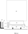
- an automated lifting mechanism may elevate the axles 700 and vehicle chassis 106 of the vehicle 100 to a suitable working height.
- each dolly 400 may be provided with different mechanical holders (not shown) that are adapted for a specific types of axles 700. This allows for a convenient access by an wheel mounting operator to the wheel assembly and wheel hub 701 on the axles 700 along the assembly line 600.
- the dollies 400 may then jointly convey the axles 700 and vehicle chassis 106 of the vehicle 100 at the suitable working height along the assembly line 600.
- assembly line tools 500 such as, e.g. a wheel lifting trolley or spindle tool, may be employed by wheel mounting operators to carry a wheel 110 for fixation to an axle 700 carried by the dolly 400.
- the assembly line tools 500 potentially comprising pneumatic or electric wrenches, are utilized to affix the wheel 110 to the wheel hub 701 of the axle 700 using nuts or bolts.
- the assembly line tools 500 may aligns the bolt pattern on the wheel 110 with the corresponding pattern on the wheel hub of the axle 700, promoting accurate placement.
- the assembly line tools 500 may also comprise a pneumatic system and/or electric motors to lift, carry and rotate the wheel 110 in order to affix the wheel 110 to the wheel hub 701 of the axle 700.
- Embodiments of a computer-implemented method for localizing an assembly line tool 500 with respect to at least one axle 700-704 of a vehicle 100 located on an assembly line 600 will now be described with reference to the flowchart depicted in FIG. 5 .
- the assembly line 600 comprise at least two dollies 400-404, as exemplified in FIG. 4 and FIG. 6 .
- each dolly 400-404 is configured to move along the assembly line 600 and to carry a respective axle 700-704 of the vehicle 100 being assembled on the assembly line 600, as also exemplified in FIGS. 4 and 6 .
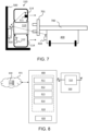
- Each dolly 400-404 comprises a short range wireless transmitter 410, as also exemplified in FIG. 7 .
- the assembly line 600 comprise at least one assembly line tool 500 comprising a short range wireless receiver 510, as also exemplified in FIG. 7 .
- FIG. 5 is an illustrated example of actions, steps or operations which may be performed by the system 800 described below with reference to FIG. 8 .
- the method may comprise the following actions, steps or operations.
- the system 800 obtains a sequence of dolly identities, IDs, according to an order of sequence of which the at least two dollies 400-404 are moving along the assembly line 600. This is, for example, exemplified and illustrated in FIG. 6 in which each of the dollies 400-404 are ordered in specific sequence on the assembly line 600.
- the system 800 may comprise or be connected to a dolly handling system 831 and thus be able to receive or retrieve the sequence of dolly identities, IDs, according to an order of sequence of which the at least two dollies 400-404 are moving along the assembly line 600 from the dolly handling system 830.
- the system 800 may be connected to a central or cloud-based data storage facility 831 in which the dolly handling system 831 may store information and thus be able to receive or retrieve the sequence of dolly identities, IDs, according to an order of sequence of which the at least two dollies 400-404 are moving along the assembly line 600 from the central or cloud-based data storage facility 831.
- the dolly handling system 831 and the central or cloud-based data storage facility 831 are exemplified in FIG. 8 .
- Such a dolly handling system 830 may be responsible for planning and handling the operations of the dollies on the assembly line 600 in view of the vehicle 100 and vehicle chassis 106 that is planned or scheduled to be assembled.
- the dolly handling system 830 may be configured to control the dollies such that the correct sequence of dollies are lined up and fitted to receive the vehicle chassis 106 and all of its specific axles 700-704 in accordance with the predetermined axle layout of the vehicle chassis 106, e.g. the axle layout H in FIG. 6 .
- a front axle of the vehicle chassis 106 may always come before the drive axle of the vehicle chassis 106, etc.
- the predetermined axle layout of the vehicle chassis 106 may be identified by the dolly handling system 830 based on an identified chassis ID of the vehicle chassis 106.
- the dolly handling system 830 may also be arranged to communicate with the short range wireless transmitters 410 of each of the at least two dollies 400-404, for example, in order to scan and check that the correct sequence of dollies are actually lined up on the assembly line 600 according to the planned or scheduled vehicle 100 to be assembled.
- the short range wireless transmitters 410 of each of the at least two dollies 400-404 may also be referred to as integrated anchors or RFID tags.
- the system 800 may also be connected directly to one or more the short range wireless receivers (not shown), such as, e.g. RFID scanners/readers, adapted to scan/read the short range wireless transmitters 410 of each of the at least two dollies 400-404, such as, e.g. integrated anchors or RFID tags in each of the dollies 400-404, on the assembly line 600 prior to reaching the wheel mounting station of the assembly line tool 500 on the assembly line 600.
- the system 800 may be arranged to directly scan and check that the correct sequence of dollies are actually lined up on the assembly line 600 according to the planned or scheduled vehicle 100 to be assembled.
- the vehicle 100, the vehicle chassis 106 and the respective axle 700-704 of the vehicle 100 to be assembled may here be identified by a chassis ID received or retrieved, for example, from the dolly handling system 830, the central or cloud-based data storage facility 831 or other assembly line planning system 831.
- the system 800 After obtaining the sequence of dolly IDs in Action 501, the system 800 associate each dolly ID in the obtained sequence of dolly IDs with a specific axle in a predetermined axle layout associated with the vehicle 100 based on the order of sequence. This means that the system 800 may, e.g. based on an obtained chassis ID identifying the specific predetermined axle layout associated with the vehicle 100 to be assembled and thus also its specific axle configuration, determine that the first dolly ID in the order of sequence of the obtained sequence of dolly IDs in Action 501 is carrying a front axle according to the specific predetermined axle layout associated with the vehicle 100 to be assembled.
- the system 800 may also determine that the second and further dolly IDs in the order of sequence of the obtained sequence of dolly IDs in Action 501 is carrying the next axle, e.g. a drive axle (D), pusher axle (P), tag axle (T), etc., according to the specific predetermined axle layout associated with the vehicle 100 to be assembled.
- This information may thus be collected and stored by the system 800, for example, in a table as illustrated in FIG. 6 . It should here be noted that this information may be collected and stored by the dolly handling system 830 prior to the vehicle 100 arriving to the wheel mounting station of the assembly line tool 500 along the assembly line 600, or be collected and stored by the system 800 as the vehicle 100 arrives to the wheel mounting station of the assembly line tool 500 along the assembly line 600.
- the vehicle 100 to be assembled on the assembly line 600 and moving along the assembly line 600 has been identified by the system 800 as having the specific predetermined axle layout H based on e.g. its vehicle chassis ID.
- a number of different predetermined axle layouts A-K are exemplified in FIG. 9 .
- the specific predetermined axle layout H comprise a 5-axle vehicle comprising a front axle (F1) 700, a first pusher axle (P1) 701, a first drive axle (D1) 702, a second drive axle (D2) 703, and a first tag axle (1) 704.
- the system 800 obtains, from the short range wireless transmitter 410 of at least a first dolly 400 using the short range wireless receiver 510 of the assembly line tool 500, at least the first dolly ID of the at least first dolly 400.
- the system 800 may receive the first dolly ID, e.g. ID_1 in the table shown in FIG.
- the short range wireless receiver 510 of the at least one assembly line tool 500 is configured to receive wireless signals from the short range wireless transmitter 410 of each dolly 400-404.
- the short range wireless receiver 510 of the assembly line tool 500 may comprise a RFID reader that is reading an RFID tag integrated in each dolly 400-404, wherein each RFID tag is programmed with each corresponding dolly ID.
- the short range wireless receiver 510 of the assembly line tool 500 may be adapted to receive the tire information at one of the established industry standard frequencies of 315/433/868/915/1900/2450 MHz from the tire pressure/temperature sensor (TPS) of the wheel 110.
- TPS tire pressure/temperature sensor
- the system 800 may pair the tire sensors 111, such as, TPS sensors, and identity tags 112, such as, RFIDs, by means of activating the TPS and interrogating the RFID tag of the tire 114 or rim 113 of the wheel 110.
- a sensor ID of the tire 114 e.g. RFID tag 112
- This RFID/TPS pairing may also, for example, be stored, saved and used later when the vehicle 100 is visiting a workshop. In this case, only the RFID inside tire 114 is needed to be read in order to know the TPS ID inside the tire 114 of the wheel 110.
- An advantage of such an approach is that the TPS sensor 111 is not required to be activated, but leaving this to the RFID tag which is more easily read.
- each wheel 110 and its tire information are read and paired individually.
- the reading by the short range wireless receiver 510 of the assembly line tool 500 is made much simpler than reading a double/twin wheel combination at the same time.
- one problem with double/twin mounted wheels is due to random location of RFID tags 112 inside the tires 114. In some circumstances, the RFID tags 112 may be very close to each other in a double/twin mount, which makes it more difficult to decide which RFID tag 112 and TPS ID 111 belongs to which tire 114 and wheel 110.
- the system 800 may pair the tire sensors 111, such as, TPS sensors, and identity tags 112, such as, RFIDs, of twin wheel mounts by reading the inner and outer wheels in sequence.
- the inner wheel is naturally always mounted first, while the outer wheel is mounted last.
- the inner wheel already mounted may be distinguished from outer wheel when mounted, even though the system 800 will be receive the same dolly ID when mounting both the inner and outer wheel of the twin wheel mount on the axle of the vehicle 100.
- the system 800 may associate the obtained tire information with the determined location of the assembly line tool 500 with respect to the specific axle in the predetermined axle layout associated with the vehicle 100. This means, for example, that the system 800 may pair the tire sensors 111 and identity tags 112, such as, TPS and RFID sensors, of the wheel 110 to a vehicle axle, e.g. the first front axle (F1) 700, belonging to a specific vehicle chassis ID, e.g. the chassis ID of the vehicle chassis 106, by means of reading of the short range wireless transmitters 410 of the first dolly 400 carrying the axle, i.e. the first front axle (F1) 700.
- a vehicle axle e.g. the first front axle (F1) 700
- a specific vehicle chassis ID e.g. the chassis ID of the vehicle chassis 106
- the system 800 may generate an alert signal in case the obtained tire information and the specific axle association is not compliant with an approved tire/axle combination.
- the system 800 may check that the pairing or association between the tire sensors 111 and identity tags 112, such as, TPS and RFID sensors, of the wheel 110 and the specific axle in the predetermined axle layout associated with the vehicle 100, e.g. the first front axle (F1) 700, is correct and matches with a predetermined and approved tire/axle combination.
- the wheel 110 comprising the tire sensors 111 and identity tags 112 may be adapted to be mounted onto the specific axle in the predetermined axle layout associated with the vehicle 100, e.g. the first front axle (F1) 700.
- the embodiments of the system 800 described herein may be considered as independent examples, or may be considered in any combination with each other to describe non-limiting examples. It should also be noted that, although not shown in FIG. 8 , it should be noted that known conventional features of a system 800, such as, for example, a connection to the mains, network connections (e.g. input/output ports, etc.), etc., may be assumed to be comprised in the system 800 but is not shown or described any further in regards to FIG. 8 .
- the system 800 may comprise one or more centrally located or distributed network unit(s), wherein the system 800 and the one or more network unit(s) may comprise processing circuitry 810 and a memory 820.
- the processing circuitry 810 may also comprise an obtaining module 811, an associating module 812, a determining module 813, and a generating module 814, each responsible for providing its functionality to support the examples described herein.
- the system 800 may also be connected to a dolly handling system 831 or a central or cloud-based data storage facility 830 connected or comprised in the dolly handling system 831. Further, the system 800 may also be connected to an assembly line tool 500 comprising a short range wireless receiver 510.
- the system 800 or processing circuitry 810 is configured to, or may comprise the obtaining module 811 configured to, obtain a sequence of dolly identities, IDs, according to an order of sequence of which the at least two dollies 400-404 are moving along the assembly line 600.
- the system 800 or processing circuitry 810 is also configured to, or may comprise the associating module 812 configured to, associate each dolly ID in the obtained sequence of dolly IDs with a specific axle in a predetermined axle layout associated with the vehicle 100 based on the order of sequence.
- the system 800 or processing circuitry 810 is further configured to, or may comprise the obtaining module 811 configured to, obtain, from the short range wireless transmitter 410 of at least a first dolly 400 using the short range wireless receiver 510 of the assembly line tool 500, at least a first dolly ID of the at least first dolly 400. Furthermore, the system 800 or processing circuitry 810 is further configured to, or may comprise the determining module 813 configured to, determine a location of the assembly line tool 500 with respect to a specific axle in the predetermined axle layout associated with the vehicle 100 based on the obtained first dolly ID and the specific axle associated thereto.
- the at least one assembly line tool 500 may comprise either a trolley, or a spindle tool, configured to carry a wheel 110 for fixation to an axle 700-704 carried by one of the at least two dollies 400-404.
- the system 800 or processing circuitry 810 may further configured to, or may comprise the obtaining module 811 configured to, obtain, from the short range wireless receiver 510 of the assembly line tool 500, tire information from a wheel 110 carried by the at least one assembly line tool 500.
- the system 800 or processing circuitry 810 may also configured to, or may comprise the associating module 812 configured to, associate the obtained tire information with the determined location of the assembly line tool 500 with respect to the specific axle in the predetermined axle layout associated with the vehicle 100.
- the system 800 or processing circuitry 810 may further configured to, or may comprise the generating module 814 configured to, generate an alert signal in case the obtained tire information and the specific axle association is not compliant with an approved tire/axle combination.
- the tire information may originate from a identity tag 112 and/or a tire sensor 111 located in the wheel 110 or on a rim 113 of the wheel 110.
- tire information may comprise on one or more sensor IDs of the identity tag 112 and/or tire sensor 111, wherein the identity tag 112 is an Radio Frequency Identification, RFID, tag and the tire sensor 111 is a tire pressure/temperature sensor, TPS.
- the tire information may comprise one or more of: a basis state of a tire pressure/temperature sensor, TPS, a supplier ID, a type of activation/trigger mode ID, tire pressure data, tire temperature data, and battery status of a tire pressure/temperature sensor, TPS.
- the short range wireless receiver 510 of the at least one assembly line tool 500 may be configured to receive wireless signal from the short range wireless transmitter 410 of each dolly 400-404.
- the predetermined axle layout may comprise at least a front axle and a rear axle.
- the embodiments for localizing an assembly line tool 500 with respect to at least one axle 700-704 of a vehicle 100 located on an assembly line 600 described above may be implemented through one or more processors, such as the processing circuitry 810 in the system 800 depicted in FIG. 8 , together with computer program code for performing the functions and actions of the examples herein.
- the program code mentioned above may also be provided as a computer program product, for instance in the form of a data carrier carrying computer program code or code means for performing the examples herein when being loaded into the processing circuitry 810 in the system 800.
- the computer program code may e.g. be provided as pure program code in the network system 800 or on a server and downloaded to the system 800.
- modules of the system 800 may in some examples be implemented as computer programs stored in memory, e.g. in the memory modules 820 in FIG. 8 , for execution by processors or processing modules, e.g. the processing circuitry 810 of FIG. 8 .
- processors or processing modules e.g. the processing circuitry 810 of FIG. 8 .
- the processing circuitry 810 and the memory 820 described above may refer to a combination of analog and digital circuits, and/or one or more processors configured with software and/or firmware, e.g. stored in a memory, that when executed by the one or more processors such as the processing circuitry 810 perform as described above.
- processors may be included in a single application-specific integrated circuit (ASIC), or several processors and various digital hardware may be distributed among several separate components, whether individually packaged or assembled into a system-on-a-chip (SoC).
- ASIC application-specific integrated circuit
- SoC system-on-a-chip
- Relative terms such as “below” or “above” or “upper” or “lower” or “horizontal” or “vertical” may be used herein to describe a relationship of one element to another element as illustrated in the Figures. It will be understood that these terms and those discussed above are intended to encompass different orientations of the device in addition to the orientation depicted in the Figures. It will be understood that when an element is referred to as being “connected” or “coupled” to another element, it can be directly connected or coupled to the other element, or intervening elements may be present. In contrast, when an element is referred to as being “directly connected” or “directly coupled” to another element, there are no intervening elements present.
Landscapes
- Engineering & Computer Science (AREA)
- Chemical & Material Sciences (AREA)
- Combustion & Propulsion (AREA)
- Transportation (AREA)
- Mechanical Engineering (AREA)
- Manufacturing & Machinery (AREA)
- Arrangements For Transmission Of Measured Signals (AREA)
Priority Applications (2)
| Application Number | Priority Date | Filing Date | Title |
|---|---|---|---|
| EP23220369.5A EP4578768A1 (fr) | 2023-12-27 | 2023-12-27 | Système et procédé associé pour la localisation d'un outil de ligne d'assemblage par rapport à au moins un essieu d'un véhicule |
| US18/984,411 US20250214666A1 (en) | 2023-12-27 | 2024-12-17 | System and a method therein for localization of an assembly line tool with respect to at least one axle of a vehicle |
Applications Claiming Priority (1)
| Application Number | Priority Date | Filing Date | Title |
|---|---|---|---|
| EP23220369.5A EP4578768A1 (fr) | 2023-12-27 | 2023-12-27 | Système et procédé associé pour la localisation d'un outil de ligne d'assemblage par rapport à au moins un essieu d'un véhicule |
Publications (1)
| Publication Number | Publication Date |
|---|---|
| EP4578768A1 true EP4578768A1 (fr) | 2025-07-02 |
Family
ID=89386159
Family Applications (1)
| Application Number | Title | Priority Date | Filing Date |
|---|---|---|---|
| EP23220369.5A Pending EP4578768A1 (fr) | 2023-12-27 | 2023-12-27 | Système et procédé associé pour la localisation d'un outil de ligne d'assemblage par rapport à au moins un essieu d'un véhicule |
Country Status (2)
| Country | Link |
|---|---|
| US (1) | US20250214666A1 (fr) |
| EP (1) | EP4578768A1 (fr) |
Citations (5)
| Publication number | Priority date | Publication date | Assignee | Title |
|---|---|---|---|---|
| JPH0538640A (ja) * | 1991-08-07 | 1993-02-19 | Daifuku Co Ltd | 車両組立てラインへの車輪供給設備 |
| KR20040100529A (ko) * | 2003-05-23 | 2004-12-02 | 현대자동차주식회사 | 차량용 타이어의 이송장치 |
| DE102013000569A1 (de) * | 2013-01-15 | 2014-07-17 | Audi Ag | Fertigungsanlage zur Serienfertigung von Kraftfahrzeugen |
| US20210221457A1 (en) * | 2020-01-19 | 2021-07-22 | Hongcai Wen | Vehicle servicing apparatus and methods of use thereof |
| US20230386271A1 (en) * | 2022-05-24 | 2023-11-30 | Volvo Truck Corporation | Computer-implemented method and a system for providing recommendation data associated to a vehicle |
-
2023
- 2023-12-27 EP EP23220369.5A patent/EP4578768A1/fr active Pending
-
2024
- 2024-12-17 US US18/984,411 patent/US20250214666A1/en active Pending
Patent Citations (5)
| Publication number | Priority date | Publication date | Assignee | Title |
|---|---|---|---|---|
| JPH0538640A (ja) * | 1991-08-07 | 1993-02-19 | Daifuku Co Ltd | 車両組立てラインへの車輪供給設備 |
| KR20040100529A (ko) * | 2003-05-23 | 2004-12-02 | 현대자동차주식회사 | 차량용 타이어의 이송장치 |
| DE102013000569A1 (de) * | 2013-01-15 | 2014-07-17 | Audi Ag | Fertigungsanlage zur Serienfertigung von Kraftfahrzeugen |
| US20210221457A1 (en) * | 2020-01-19 | 2021-07-22 | Hongcai Wen | Vehicle servicing apparatus and methods of use thereof |
| US20230386271A1 (en) * | 2022-05-24 | 2023-11-30 | Volvo Truck Corporation | Computer-implemented method and a system for providing recommendation data associated to a vehicle |
Also Published As
| Publication number | Publication date |
|---|---|
| US20250214666A1 (en) | 2025-07-03 |
Similar Documents
| Publication | Publication Date | Title |
|---|---|---|
| US10673948B2 (en) | Trailer identification, inspection, and verification using a vehicle gateway | |
| US12077018B2 (en) | System and a method therein for enabling a determination of a location of a tire sensor on a chassis of a vehicle | |
| US10486478B2 (en) | Method for monitoring vehicle tires with a tire pressure control system | |
| JP2008506608A (ja) | 中間準備地域における在庫及びディズパッチ処理を自動化する方法及びシステム | |
| US11987080B2 (en) | Portable electronic device and method therein for locating tire sensors on a vehicle | |
| US12319099B2 (en) | Tire fitting system and a method therein for sensor discrimination | |
| US12103339B2 (en) | Tire fitting system and method therein for assisting in fitting a wheel | |
| US20250227468A1 (en) | Tractor-to-trailer verification system | |
| EP4578768A1 (fr) | Système et procédé associé pour la localisation d'un outil de ligne d'assemblage par rapport à au moins un essieu d'un véhicule | |
| US12434514B2 (en) | Tire sensor pairing system and method for pairing tire sensors | |
| US11440734B2 (en) | Article transport system | |
| US20240346430A1 (en) | System and method for tracking vehicle tires in a service shop environment | |
| EP4570533A1 (fr) | Système et procédé de surveillance de roue | |
| US12485710B2 (en) | Electronic control unit (ECU) and method therein for monitoring tire sensors in a vehicle | |
| EP4601887A1 (fr) | Ensemble roue pour véhicule | |
| EP4699290A1 (fr) | Concentrateur de communication de capteur intégré pour un véhicule |
Legal Events
| Date | Code | Title | Description |
|---|---|---|---|
| PUAI | Public reference made under article 153(3) epc to a published international application that has entered the european phase |
Free format text: ORIGINAL CODE: 0009012 |
|
| STAA | Information on the status of an ep patent application or granted ep patent |
Free format text: STATUS: THE APPLICATION HAS BEEN PUBLISHED |
|
| AK | Designated contracting states |
Kind code of ref document: A1 Designated state(s): AL AT BE BG CH CY CZ DE DK EE ES FI FR GB GR HR HU IE IS IT LI LT LU LV MC ME MK MT NL NO PL PT RO RS SE SI SK SM TR |
|
| STAA | Information on the status of an ep patent application or granted ep patent |
Free format text: STATUS: REQUEST FOR EXAMINATION WAS MADE |
|
| 17P | Request for examination filed |
Effective date: 20251029 |