EP4578799A1 - Mécanisme de fourche de palette, dispositif de stockage et d'extraction d'article, et système logistique de stockage - Google Patents
Mécanisme de fourche de palette, dispositif de stockage et d'extraction d'article, et système logistique de stockage Download PDFInfo
- Publication number
- EP4578799A1 EP4578799A1 EP24165249.4A EP24165249A EP4578799A1 EP 4578799 A1 EP4578799 A1 EP 4578799A1 EP 24165249 A EP24165249 A EP 24165249A EP 4578799 A1 EP4578799 A1 EP 4578799A1
- Authority
- EP
- European Patent Office
- Prior art keywords
- hook
- assembly
- article
- drive
- pallet fork
- Prior art date
- Legal status (The legal status is an assumption and is not a legal conclusion. Google has not performed a legal analysis and makes no representation as to the accuracy of the status listed.)
- Pending
Links
Images


Classifications
-
- B—PERFORMING OPERATIONS; TRANSPORTING
- B65—CONVEYING; PACKING; STORING; HANDLING THIN OR FILAMENTARY MATERIAL
- B65G—TRANSPORT OR STORAGE DEVICES, e.g. CONVEYORS FOR LOADING OR TIPPING, SHOP CONVEYOR SYSTEMS OR PNEUMATIC TUBE CONVEYORS
- B65G1/00—Storing articles, individually or in orderly arrangement, in warehouses or magazines
- B65G1/02—Storage devices
- B65G1/04—Storage devices mechanical
- B65G1/0407—Storage devices mechanical using stacker cranes
- B65G1/0435—Storage devices mechanical using stacker cranes with pulling or pushing means on either stacking crane or stacking area
Definitions
- the present disclosure relates to the field of logistics, in particular to a pallet fork mechanism, an article storing and extracting device, and a storage logistics system.
- pallet forks for storing and extracting are used to transfer material cases between the pallet forks and article locations in the racks.
- pallet forks for storing and extracting include clamping-type pallet forks and lifting-type pallet forks.
- a clamping-type pallet fork extends fork plates on both sides of article, and clamps the article between the fork plates and swing arms on the pallet fork plates by means of the swing arms, so as to implement transfer of the article by applying a transverse push force or a transverse pull force to the article.
- a lifting-type pallet fork supports and lifts article by means of a lifting mechanism to implement transfer of the article in conjunction with a transverse drive mechanism.
- clamping-type pallet forks and lifting-type pallet forks in the related art have requirements for spacing between material cases stored in the storage rack or a layer height of the storage rack, such that a higher rack storage density is not easy to achieve, and articles are stored and extracted by the pallet forks at a slower speed and with lower efficiency.
- embodiments of the present disclosure provide a pallet fork mechanism, an article storing and extracting device, and a storage logistics system, which are conducive to achieving a higher rack storage density.
- a pallet fork mechanism which includes: a mounting frame; a hook assembly movably provided on the mounting frame, and including a hook body, which has a hook-and-pull portion for hooking and pulling an article; and a first drive assembly in drive connection with the hook assembly and configured to drive the hook assembly to move in a first direction to achieve a function of hooking and pulling the article in the first direction by means of the hook-and-pull portion.
- the hook body also has a push portion for pushing article
- the first drive assembly is further configured to drive the hook assembly to move in a second direction to achieve a function of pushing the article in the second direction by means of the push portion.
- the hook-and-pull portion and the push portion are located on two opposite sides of the hook body in the first direction, and the second direction is a direction opposite to the first direction.
- the hook assembly includes a bracket and at least one set of hook bodies connected to the bracket, and each set of hook bodies includes a single hook body or a plurality of hook bodies located on a same side of the bracket.
- the at least one set of hook bodies includes a first set of hook bodies and a second set of hook bodies, the first set of hook bodies is located on a side of the bracket away from the second set of hook bodies in the first direction, and the second set of hook bodies is located on a side of the bracket away from the first set of hook bodies in the second direction, wherein the first drive assembly is configured to: drive the hook assembly to move in the first direction to achieve a function of hooking and pulling the article in the first direction by means of a hook-and-pull portion of the first set of hook bodies, or to achieve a function of pushing the article in the first direction by means of a push portion of the second set of hook bodies; and/or drive the hook assembly to move in the second direction to achieve a function of pushing the article in the second direction by means of a push portion of the first set of hook bodies, or to achieve a function of hooking and pulling the article in the second direction by means of a hook-and-pull portion of the second set of hook bodies.
- the at least one set of hook bodies includes a single set of hook bodies
- the first drive assembly is configured to: drive the hook assembly to move in the first direction to achieve a function of hooking and pulling the article in the first direction by means of a hook-and-pull portion of the single set of hook bodies at a first rotation position, or to achieve a function of pushing the article in the first direction by means of a push portion of the single set of hook bodies at a second rotation position, wherein the single set of hook bodies switches between the first rotation position and the second rotation position by rotation, and the single set of hook bodies at the first rotation position and the single set of hook bodies at the second rotation position are in central symmetry; and/or drive the hook assembly to move in the second direction to achieve a function of pushing the article in the second direction by means of a push portion of the single set of hook bodies at a third rotation position, or to achieve a function of hooking and pulling the article in the second direction by means of a hook-and-pull portion of the single set of hook bodies at
- the hook-and-pull portion is configured to enter or leave a hookable-and-pullable part of the article in a direction that intersects with both the first direction and the second direction.
- the hook-and-pull portion is configured to enter the hookable-and-pullable part of the article in a vertically upward direction.
- the first drive assembly includes: a hook seat connected to the hook assembly; and a first power element connected to the hook seat by a first linear transmission structure, and configured to drive, by means of the first linear transmission structure, the hook seat to move in the first direction or the second direction.
- the first linear transmission structure includes: a transmission wheel set provided on the mounting frame and connected to the first power element; and a transmission belt wound around the transmission wheel set and fixedly connected to the hook seat.
- the first drive assembly further includes: a first linear guide structure provided between the hook seat and the mounting frame, and configured to guide a movement of the hook seat relative to the mounting frame in the first direction or the second direction.
- the first linear guide structure includes: a first slide rail provided on the mounting frame and extending in the first direction; and a first slide block provided on the hook seat to slip fit with the first slide rail.
- the pallet fork mechanism further includes: a second drive assembly in drive connection with the hook assembly, and configured to drive the hook assembly to move in a third direction or in a direction opposite to the third direction, wherein the third direction is perpendicular to the first direction.
- the first direction is parallel to a horizontal plane
- the third direction is parallel to a vertical direction
- the first drive assembly includes a hook seat connected to the hook assembly
- the second drive assembly includes: a second power element connected to at least one of the hook seat and the hook assembly, and configured to drive the hook assembly to move relative to the hook seat.
- the second power element includes: a first through-shaft screw motor having a first electric motor housing fixedly connected to the hook seat, and a first lead screw running through the first electric motor housing, one end of the first lead screw being connected to the hook assembly, and the other end of the first lead screw running through the hook seat.
- the second drive assembly further includes: a second linear guide structure provided between the hook seat and the hook assembly, and configured to guide a movement of the hook assembly relative to the hook seat in the third direction or in the direction opposite to the third direction.
- the second linear guide structure includes: a second slide rail provided on the hook assembly and extending in the third direction; and a second slide block provided on the hook seat to slip fit with the second slide rail.
- the pallet fork mechanism further includes: a conveying assembly provided on the mounting frame, and configured to convey article in the first direction or the second direction.
- time ranges in which the conveying assembly and hook assembly respectively act on the article are configured to not overlap.
- the conveying assembly is located on an upper side of the mounting frame
- the pallet fork mechanism further includes: a second drive assembly in drive connection with the hook assembly or the first drive assembly, and configured to drive the hook assembly to move in the third direction or in the direction opposite to the third direction, so that the hook assembly extends or retracts relative to a conveying surface of the conveying assembly.
- the third power element includes: a second through-shaft screw motor having a second electric motor housing fixedly connected to the bracket, and a second lead screw running through the second electric motor housing, both ends of the second lead screw being connected to the mounting frame.
- clamping-type pallet forks and lifting-type pallet forks in the related art have requirements for spacing between material cases stored in a storage rack or a layer height of the storage rack, such that a higher storage rack storage density is not easy to achieve, and articles are stored and extracted by the pallet forks at a slower speed and with lower efficiency.
- embodiments of the present disclosure provide a pallet fork mechanism, an article storing and extracting device, and a storage logistics system, which are conducive to achieving a higher rack storage density.
- a pallet fork mechanism including: a mounting frame; a hook assembly movably provided on the mounting frame, and including a hook body, which has a hook-and-pull portion for hooking an article; and a first drive assembly in drive connection with the hook assembly and configured to drive the hook assembly to move in a first direction to achieve a function of hooking and pulling the article in the first direction by means of the hook-and-pull portion.
- the first drive assembly is in drive connection with the hook assembly, and drives the hook assembly to move in the first direction to enable a hook-and-pull portion of a hook body of the hook assembly to implement a function of hooking and pulling the article in the first direction, such that the hook body can cause the article to move in the first direction by hooking and pulling the article on a side facing the article.
- the hook assembly does not need to clamp or lift article, and thus can reduce the requirements for spacing between articles in an article location and the height of an article location, thus being conducive to achieving a higher rack storage density.
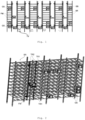
- Fig. 1 is a schematic structural diagram of some embodiments of a storage logistics system according to the present disclosure.
- a storage logistics system including a storage rack SR and an article storing and extracting device.
- the storage rack SR may be configured as a single-layer or multi-layer structure, and each layer of the storage rack SR may be provided with one or more article locations (i.e., article storage spaces) for storing the article GS.
- the plurality of article locations may be separated from each other, and may also be communicated with each other.
- the plurality of article locations in each layer may be arranged in at least one direction, such as arranged in one direction parallel to a horizontal plane or in two directions orthogonal to each other.
- the article storing and extracting device is movable relative to the storage rack SR, such as moving to a position of a site adjacent to the storage rack SR, so as to pick up the article GS from a temporary storage location in the storage rack SR (e.g., a lower article location in the storage rack SR) or from a transfer vehicle TV operating on the site, or to place the article GS taken from the storage rack SR into a temporary storage location in the storage rack SR (e.g., a lower article location in the storage rack SR) or into a transfer vehicle TV operating on the site.
- the transfer vehicle TV may put the article GS transported thereon into a temporary storage location in the storage rack SR, or take and transport away a temporary storage location in the storage rack SR.
- Fig. 2 is a schematic diagram of a mounting structure of an article storing and extracting device on a storage rack in embodiments of a storage logistics system according to the present disclosure.
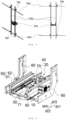
- Fig. 3 is a schematic structural diagram of some embodiments of an article storing and extracting device according to the present disclosure.
- embodiments of the present disclosure provide an article storing and extracting device including a pallet fork mechanism FM.
- the article storing and extracting device may be provided on a storage rack SR.
- the article storing and extracting device may, but not limited to, be applied in a storage logistics system.
- the article storing and extracting device may include two transversely extending first tracks TR1 and two vertically extending second tracks TR2.
- the two first tracks TR1 are arranged spaced apart in a vertical direction.
- the first tracks TR1 may be mounted on a frame of the storage rack SR, and may also be formed by the frame of the storage rack SR.
- a frame cross beam of the highest layer of the storage rack SR and a frame cross beam of a layer of the storage rack SR adjacent to the site may be used as the two first tracks TR1, respectively.
- the two second tracks TR2 are arranged spaced apart in a transverse direction, and the pallet fork mechanism FM may have end portions movably connected to the two tracks TR2, respectively, and is located on a side away from the storage rack SR, of an operating plane formed by the two second tracks TR2. Moreover, the pallet fork mechanism FM may be located between the two second tracks TR2 to allow the article GS to pass through a gap between the two second tracks TR2.
- Fig. 4 is a schematic structural diagram of some embodiments of a pallet fork mechanism according to the present disclosure.
- Fig. 5 is a schematic structural diagram of carrying the article in embodiments of a pallet fork mechanism according to the present disclosure.
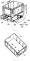
- Fig. 6 is a schematic structural diagram of the article as applied in embodiments of a pallet fork mechanism according to the present disclosure.
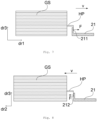
- Fig. 7 is a schematic principle diagram of hooking and pulling the article in a first direction in embodiments of a pallet fork mechanism according to the present disclosure.
- embodiments of the present disclosure provide a pallet fork mechanism FM.
- the article storing and extracting device includes the pallet fork mechanism FM.
- the pallet fork mechanism FM may, but not limited to, be applied in an article storing and extracting device.
- the pallet fork mechanism FM includes a mounting frame 10, a hook assembly 20, and a first drive assembly 30.
- the hook assembly 20 is movably provided on the mounting frame 10.
- the hook assembly 20 includes a hook body 21.
- the hook body 21 has a hook-and-pull portion 211 for hooking and pulling the article GS.
- the first drive assembly 30 is in drive connection with the hook assembly 20 and is configured to drive the hook assembly 20 to move in a first direction dr1 to achieve a function of hooking and pulling the article GS in the first direction dr1 by means of the hook-and-pull portion 211.
- the mounting frame 10 may be of a frame structure to facilitate mounting of the hook assembly 20 and the first drive assembly 30 and to reduce or eliminate a risk of the hook assembly 20 interfering with the mounting frame 10 during operation.
- the mounting frame 10 may also be in other structural form, such as a plate-type structure or a box-type structure.
- the hook body 21 of the hook assembly 20 can implement hooking and pulling of the article GS, and accordingly, the hook body 21 has a hook-and-pull portion 211.
- the form of the hook body 21 may be an L-shape, a U-shape, or other shape.
- the hook-and-pull portion 211 can enter a hookable-and-pullable part HP of the article GS from at least one side of the hookable-and-pullable part HP in order to reach a position where the article GS may be hooked and pulled.
- Fig. 6 shows the article GS in the form of an article box, having an interior space in which whole or bulk items may be contained.
- a hooking slot as the hookable-and-pullable part HP may be provided on an outer wall of the article GS, so that the hook-and-pull portion 211 of the hook body 21 hooks and pulls an inner wall of the hooking slot to achieve the function of hooking and pulling the article GS.
- the hooking slot may be a slot fixed to a side of the article by means of a sheet metal or plastic piece, and may also be formed by injection molding integrally with the article box.
- the hook body 21 may move in the first direction dr1 under the drive of the first drive assembly 30, and accordingly, the hook-and-pull portion 211 of the hook body 21 can apply a force F in the first direction dr1 to the hookable-and-pullable part HP of the article GS, so that the article GS move at a certain speed and a certain acceleration in the first direction dr1.
- the pallet fork mechanism FM can pull out the article GS in an article location to the pallet fork mechanism FM by means of the hook-and-pull portion 211 of the hook body 21.
- the hook body 21 may, on a side facing the article GS, hook and pull the article GS, without acting on the article GS from left and right sides, a back side, or a bottom side of the article GS in order to implement the movement of the article GS as in the cases of a clamping-type pallet fork and a lifting-type pallet fork in the related art, so the requirements for spacing between article in an article location and the height of an article location can be reduced, thus being conducive to achieving a higher rack storage density.
- Fig. 8 is a schematic principle diagram of pushing article in a second direction in embodiments of a pallet fork mechanism according to the present disclosure.
- the hook body 21 also has a push portion 212 for pushing the article GS.
- the first drive assembly 30 is further configured to drive the hook assembly 20 to move in a second direction dr2 to achieve a function of pushing the article GS in the second direction dr2 by means of the push portion 212.
- the first drive assembly 30 may drive the hook assembly 20 to move in the second direction dr2.
- the second direction dr2 may be a direction opposite to the first direction dr1, i.e., the second direction dr2 is parallel to and opposite to the first direction dr1.
- the second direction dr2 may cross the first direction dr1 at an acute, obtuse, or right angle.
- the push portion 212 of the hook body 21 can achieve the function of pushing the article GS.
- the push portion 212 may act on the outside of the hookable-and-pullable part HP of the article GS, and by applying a force F in the second direction dr2, may cause the article GS to move at a certain speed and a certain acceleration in the second direction dr2.
- the push portion 212 may, but not limited to, act on the outside of the hookable-and-pullable part HP, and may also act on other parts on a side of the article GS facing the push portion.
- the first drive assembly 30 further includes a first linear guide structure 34.
- the first linear guide structure 34 is provided between the hook seat 31 and the mounting frame 10, and is configured to guide the movement of the hook seat 31 relative to the mounting frame 10 in the first direction dr1 or the second direction dr2.
- the first linear guide structure 34 can assist the first linear transmission structure 33 so that the hook seat 31 stably moves linearly in the first direction d1 or the second direction dr2, to reduce the risk of the article GS falling off due to instability during movement.
- the first direction dr1 is parallel to the horizontal plane
- the third direction dr3 is parallel to the vertical direction. That is, the hook assembly 20 can achieve a hooking and pulling function in the horizontal direction, and arrive at or leave a position where the article GS may be hooked and pulled, in the vertical direction.
- the hook assembly 20 can achieve a hooking and pulling function in the horizontal direction, and arrive at or leave a position where the article GS may be hooked and pulled, in the vertical direction.
- the first lead screw 412 may move forward or backward in an extension direction of the first lead screw 412.
- the hook assembly 20 can be caused to move away from or close to the hook seat 43 when the first lead screw 412 moves relative to the first electric motor housing 411.
- the extension direction of the first lead screw 412 is parallel to the third direction dr3.
- a screw length between the hook seat 43 and the hook assembly 20 may be reduced with the increase of a screw length passed through the hook seat 31, which is conducive to achieving a more compact structure.
- the first electric motor housing 411 can also form a function of supporting and limiting the hook assembly 20.
- the second linear guide structure 42 may include a second slide rail 421 and a second slide block 422.
- the second slide rail 421 is provided on the hook assembly 20, and extends in the third direction dr3.
- the second slide block 422 is provided on the hook seat 31 to slip fit with the second slide rail 421.
- the second slide rail 421 may be provided on a bracket, which extends in the third direction dr3, of the hook assembly 20, and may also be fixedly connected to the hook assembly 20 to serve as a bracket of the hook assembly 20.
- the second linear guide structure 42 may be in other structural form, such as a guide structure in which a plain shaft mates with a sleeve.
- Figs. 12 and 13 respectively illustrate different relative positions of the second slide rail 421 and the second slide block 422, and different relative distances between the hook seat 31 and the hook assembly 20, under the guide of the second linear guide structure 42.
- the time ranges in which the conveying assembly 50 and hook assembly 20 respectively act on the article GS are configured to not overlap.
- the article GS are first hooked and pulled by the hook assembly 20, and after being hooked and pulled a preset displacement, the article GS is further conveyed by the conveying assembly 50 instead.
- the article GS are first conveyed by the conveying assembly 50, and after conveyed a preset displacement, the article GS are pushed by the hook assembly 30 instead. This configuration can effectively reduce the risk of the conveying assembly 50 and the hook assembly 20 interfering with each other.
- This configuration allows the conveying assembly 50 and the hook assembly 20 to act on the article GS in the same direction, and increases a driving force on the article GS, thereby meeting the driving need of heavier article GS, and accordingly making it easy to achieve a cohesive process in which the conveying assembly 50 and the hook assembly 20 respectively act on the article GS, which is conducive to improving the efficiency.
- the conveying assembly 50 is located on an upper side of the mounting frame 10, and the pallet fork mechanism FM further includes a second drive assembly 40.
- the second drive assembly 40 is in drive connection with the hook assembly 20 or the first drive assembly 30, and is configured to drive the hook assembly 20 to move in the third direction dr3 or in the direction opposite to the third direction dr3, so that the hook assembly 20 extends or retracts relative to a conveying surface of the conveying assembly 50.
- Fig. 14 is a schematic diagram of a mounting structure of a bracket and a third drive assembly in embodiments of a pallet fork mechanism according to the present disclosure.
- the pallet fork mechanism FM further includes a bracket 60.
- the mounting frame 10 is fixedly, detachably or movably provided on the bracket 60.
- the bracket 60 may be movably provided relative to the second rails TR2 in embodiments of an article storing and extracting device.
- the bracket 60 may include two L-shaped vertical plates 61, and at least one transverse plate 62 that connects the two L-shaped vertical plates 61 and is located between the two L-shaped vertical plates 61.
- the two transverse plates 62 are arranged spaced apart in the first direction dr1.
- the mounting frame 10 may be fixedly connected to the bracket 60 (also including the case where they are formed integrally) such that the mounting frame 10 may move synchronously with the movement of the bracket 60.
- the mounting frame 10 may also be detachable relative to the bracket 60 such that the mounting frame 10 and the structure thereon may be detached together from the bracket 60 to facilitate maintenance and replacement.
- the pallet fork mechanism FM further includes a third drive assembly 70.
- the third drive assembly 70 is provided on the bracket 60 and in drive connection with the mounting frame 10, and is configured to drive the mounting frame 10 to move relative to the bracket 60 in the first direction dr1 or in the direction opposite to the first direction dr1.
- the mounting frame 10 may move in the first direction dr1 or in the direction opposite to the first direction dr1 under the drive of the third drive assembly 70. In this way, the position of the mounting frame 10 may be adjusted in a direction same as or opposite to the direction of movement of the article GS to facilitate transition of the article GS between the article location and the pallet fork mechanism.
- the third drive assembly 70 further includes a third power element 71.
- the third power element 71 is connected to both the mounting frame 10 and the bracket 60, and is configured to drive the mounting frame 10 to move relative to the bracket 60.
- the third power element 71 may include an electric motor or a pneumatic motor, and drives the mounting frame 10 so that the mounting frame 10 moves relative to the bracket 60 in the first direction dr1 or in the direction opposite to the first direction dr1.
- the third drive assembly 70 further includes a third linear guide structure 72.
- the third linear guide structure 72 is provided between the bracket 60 and the mounting frame 10, and is configured to guide the movement of the mounting frame 10 relative to the bracket 60 in the first direction dr1 or in the direction opposite to the first direction dr1.
- the third linear guide structure 72 includes a third slide rail 721 and a third slide block 722.
- the third slide rail 721 is provided on the mounting frame 10 and extends in the first direction dr1.
- the third slide block 722 is provided on the bracket 60 to slip fit with the third slide rail 721.
- a plurality of third slide blocks 722 may be provided, and distributed on at least two transverse plates 62.
- the third slide rail 721 may be provided on a bottom surface of the mounting frame 10.
- a continuous slide guiding effect can be achieved between the third slide rail 721 and the third slide block 722, so that the movement of the mounting frame 10 relative to the bracket 60 is smoother and more stable.
- the third linear guide structure 72 may be in other structural form, such as a guide structure in which a plain shaft mates with a sleeve.
- the hook assembly 20 may include a bracket 22 and at least one set of hook bodies 21 connected to the bracket 22, each set of hook bodies 21 including a single hook 21 or a plurality of hook bodies 21 located on a same side of the bracket 22.
- the configuration of the hook body 21 can implement storage of article on a single side or different sides.
- the at least one set of hook bodies 21 includes a first set of hook bodies 21a and a second set of hook bodies 21b.
- the first set of hook bodies 21a is located on a side of the bracket 22 away from the second set of hook bodies 21b in the first direction dr1
- the second set of hook bodies 21b is located on a side of the bracket 22 away from the first set of hook bodies 21a in the second direction dr2.
- the first set of hook bodies 21a includes two hook bodies 21a arranged spaced apart in a fourth direction dr4
- the second set of hook bodies 21b includes two hook bodies 21b arranged spaced apart in the fourth direction dr4.
- the fourth direction dr4 is perpendicular to the third direction dr3 and perpendicular to the first direction dr1 or the second direction dr2.
- the first drive assembly 30 can drive the hook assembly 20 to move in the first direction dr1 to achieve a function of hooking and pulling the article GS in the first direction dr1 by means of a hook-and-pull portion 211 of the first set of hook bodies 21a, or to achieve a function of pushing the article GS in the first direction dr1 by means of a push portion 212 of the second set of hook bodies 21b.
- the first drive assembly 30 can also drive the hook assembly 20 to move in the second direction dr2 to achieve a function of pushing the article GS in the second direction dr2 by means of a push portion 212 of the first set of hook bodies 21a, or to achieve a function of hooking and pulling the article GS in the second direction dr2 by means of a hook-and-pull portion 211 of the second set of hook bodies 21b.
- the first drive assembly 30 may drive the hook assembly 20 to move in the first direction dr1, and may also drive the hook assembly to move in the direction opposite to the first direction dr1, and achieves a function of hooking and pulling the article GS in the direction of movement of the hook assembly 20 or a function of pushing the article GS in the direction of movement of the hook assembly 20, which enables the pallet fork mechanism to perform operations of storing and extracting article on different sides between neighboring storage racks.
- Fig. 15 is a schematic diagram of rotation for the form of a single set of hook bodies in embodiments of a pallet fork mechanism according to the present disclosure.
- the at least one set of hook bodies 21 includes a single set of hook bodies 21.
- the first drive assembly 30 can drive the hook assembly 20 to move in the first direction dr1 to achieve a function of hooking and pulling the article GS in the first direction dr1 by means of a hook-and-pull portion 211 of the single set of hook bodies 21 at a first rotation position, or to achieve a function of pushing the article GS in the first direction dr1 by means of a push portion 212 of the single set of hook bodies 21 at a second rotation position, wherein the single set of hook bodies 21 switches between the first rotation position and the second rotation position by rotation, and the single set of hook bodies 21 at the first rotation position and the single set of hook bodies 21 at the second rotation position are in central symmetry.
- the first drive assembly 30 can also drive the hook assembly 20 to move in the second direction dr2 to achieve a function of pushing the article GS in the second direction dr2 by means of the push portion 212 of the single set of hook bodies 21 at a third rotation position, or to achieve a function of hooking and pulling the article GS in the second direction dr2 by means of the hook-and-pull portion 211 of the single set of hook bodies 21 at a fourth rotation position, wherein the single set of hook bodies 21 switches between the third rotation position and the fourth rotation position by rotation, and the single set of hook bodies 21 at the third rotation position and the single set of hook bodies 21 at the fourth rotation position are in central symmetry.
- a solid line form of the hook body 21 indicates a situation in which the single set of hook bodies 21 is at a rotation position on a left side of the bracket 22, which can implement hooking and pulling of the article GS on the left side or pushing of the article GS on the left side.
- the single set of hook bodies 21 as indicated by a dashed line form are located at a rotation position on a right side of the bracket 22, which can implement hooking and pulling of the article GS on the right side or pushing of the article GS on the right side.
- the hook-and-pull portion 211 can enter or leave the hookable-and-pullable part HP of the article GS in a direction that intersects with both the first direction dr1 and the second direction dr2.
- the direction in which the hook-and-pull portion 211 enters the hookable-and-pullable part HP may be perpendicular to the first direction dr1 or the second direction dr2, or at an acute or obtuse angle relative to the first direction dr1 and the second direction dr2.
- the direction in which the hook-and-pull portion 211 enters the hookable-and-pullable part HP of the article GS is the third direction dr3, and the direction in which it leaves the hookable-and-pullable part HP is the direction opposite to the third direction dr3. That is, in some embodiments, the hook-and-pull portion 211 is configured to enter the hookable-and-pullable part HP of the article GS in a vertically upward direction.
- the hook-and-pull portion may enter the hookable-and-pullable part HP when the hook assembly 20 extends upwardly relative to the conveying surface of the conveying assembly 50, and the hook-and-pull portion may leave the hookable-and-pullable part HP when the hook assembly retracts downwardly relative to the conveying surface of the conveying assembly 50, which is conducive to simplifying the operations and improving the efficiency.
- Fig. 17 illustrates a situation in which a hook-and-pull portion 211 of a hook body 21 enters a hookable-and-pullable part HP of the article GS in a direction opposite to the third direction dr3.
- the third direction dr3 here may be a vertical upward direction.
- the number of hook body included in each set of hook bodies included in the hook assembly may be arranged in pair and spaced apart in the fourth direction dr4, the combination of the transmission wheel set and the transmission belt included in the first drive assembly may be arranged in pair and spaced apart in the fourth direction dr4, the conveying members included in the conveying assembly may also be arranged in pair and spaced apart in the fourth direction dr4, and the slide rails and slide blocks included in the first, second, and third linear guide structures may also be arranged in pair and spaced apart in the fourth direction dr4, which will not be described here.
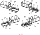
- Fig. 20 shows, in (a)-(d), respectively, three-dimensional schematic diagrams of hooking and pulling and pushing the article in a first direction, and hooking and pulling and pushing article in a second direction, respectively, in embodiments of a pallet fork mechanism according to the present disclosure
- FIG. 20 shows, in (a)-(d), respectively, three-dimensional schematic diagrams of hooking and pulling and pushing the article in a first direction, and hooking and pulling and pushing article in a second direction, respectively, in embodiments of a pallet fork mechanism according to the present disclosure
- FIG. 20 shows, in (a)-(d), respectively, three-dimensional schematic diagrams of hooking and pulling and pushing the article in a first direction, and hooking and pulling and pushing article in a second direction, respectively, in embodiments of a pallet fork mechanism according to the present disclosure
- FIG. 20 shows, in (a)-(d), respectively, three-dimensional schematic diagrams of hooking and pulling and pushing the article in a first direction, and hooking and pulling and pushing article in
- the pallet fork mechanism performs a pushing operation on the article GS located on a left side of the pallet fork mechanism, at which time the first set of hook bodies 21a of the hook assembly pushes against an outer side of the hookable-and-pullable part of the article GS, and the article GS are caused to move in the second direction dr2 under the drive of the first driving assembly 30 so that the article GS move away from the transferring mechanism 50.
- the pallet fork mechanism performs a hooking and pulling operation on the article GS located on a right side of the pallet fork mechanism, at which time the second set of hook bodies 21b of the hook assembly has entered the hookable-and-pullable part of the article GS, and the article GS are caused to move in the second direction dr2 under the drive of the first drive assembly 30 so that the article GS reaches above the conveying mechanism 50.
- the pallet fork mechanism moves to a position adjacent to the article location of the article GS to be picked up, at which time the conveying surface of the conveying mechanism 50 is substantially flush with a bottom surface of the article location. At that time, the hook assembly 20 is under the conveying surface of the conveying mechanism 50 and moves toward the article GS.
- the hook assembly 20 has moved to a position adjacent to the article GS, at which position the hook assembly 20 is transversely substantially aligned with a hooking slot on a right side surface of the article GS.
- the hook assembly 20 translates upwardly, and a portion of the hook assembly 20 is exposed above the conveying surface of the conveying mechanism 50.
- the hook assembly 20 moves right, causing the article GS to move right as well, so that a portion of the article GS reaches the top of the conveying mechanism 50.
- the hook assembly 20 may move from a left end of the stroke of the pallet fork mechanism to a right end of the stroke of the pallet fork mechanism, at which time a portion of the article GS has not yet reached the top of the conveying mechanism 50.
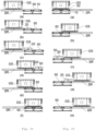
- Fig. 22 shows, in (a)-(e), respectively, schematic diagrams of a process of transferring article on a pallet fork mechanism to an article location in embodiments of a pallet fork mechanism according to the present disclosure.
- the process is illustrated by (a)-(e) in Fig. 22 .
- the pallet fork mechanism moves to a position adjacent to the article location in which the article GS are stored, at which time the conveying surface of the conveying mechanism 50 is substantially flush with a bottom surface of the article location. At that time, the hook assembly 20 is located under the conveying surface of the conveying mechanism 50.
- the article GS are conveyed right by a conveying operation of the conveying mechanism 50 so that a portion of the article GS enters the article location.
Landscapes
- Engineering & Computer Science (AREA)
- Mechanical Engineering (AREA)
- Warehouses Or Storage Devices (AREA)
- Transportation (AREA)
- Structural Engineering (AREA)
- Civil Engineering (AREA)
- Life Sciences & Earth Sciences (AREA)
- Geology (AREA)
Applications Claiming Priority (1)
| Application Number | Priority Date | Filing Date | Title |
|---|---|---|---|
| CN202311836799.3A CN117775570A (zh) | 2023-12-28 | 2023-12-28 | 货叉机构、货物存取装置及仓储物流系统 |
Publications (1)
| Publication Number | Publication Date |
|---|---|
| EP4578799A1 true EP4578799A1 (fr) | 2025-07-02 |
Family
ID=90396093
Family Applications (1)
| Application Number | Title | Priority Date | Filing Date |
|---|---|---|---|
| EP24165249.4A Pending EP4578799A1 (fr) | 2023-12-28 | 2024-03-21 | Mécanisme de fourche de palette, dispositif de stockage et d'extraction d'article, et système logistique de stockage |
Country Status (6)
| Country | Link |
|---|---|
| EP (1) | EP4578799A1 (fr) |
| JP (1) | JP2025105393A (fr) |
| KR (1) | KR20250103357A (fr) |
| CN (1) | CN117775570A (fr) |
| AU (1) | AU2024357302A1 (fr) |
| WO (1) | WO2025138444A1 (fr) |
Families Citing this family (9)
| Publication number | Priority date | Publication date | Assignee | Title |
|---|---|---|---|---|
| CN118270433A (zh) * | 2024-05-10 | 2024-07-02 | 北京京东乾石科技有限公司 | 货物纠偏装置、方法、系统以及可读存储介质 |
| CN118270434A (zh) * | 2024-05-10 | 2024-07-02 | 北京京东乾石科技有限公司 | 取货方法、取货系统、存储介质及程序产品 |
| CN118977955A (zh) * | 2024-09-25 | 2024-11-19 | 北京京东远升科技有限公司 | 穿梭车、立体库存取系统和取货方法 |
| CN118953930A (zh) * | 2024-09-27 | 2024-11-15 | 北京京东远升科技有限公司 | 货物存取机构、货物存取装置及仓储物流系统 |
| CN118992377A (zh) * | 2024-09-27 | 2024-11-22 | 北京京东远升科技有限公司 | 取放机构、其零点定位方法、货物存取装置及仓储系统 |
| CN118977956A (zh) * | 2024-09-27 | 2024-11-19 | 北京京东远升科技有限公司 | 货物存取装置及仓储物流系统 |
| US20260159320A1 (en) * | 2024-12-06 | 2026-06-11 | Locus Robotics Corp. | Tote manipulator mechanism |
| CN120646432B (zh) * | 2025-08-01 | 2026-07-07 | 浙江中扬立库技术有限公司 | 一种可自主取货的牵引车 |
| CN121341586B (zh) * | 2025-12-18 | 2026-04-14 | 北京京东远升科技有限公司 | 货物存取机构、料箱立体库系统以及货物存取方法 |
Citations (5)
| Publication number | Priority date | Publication date | Assignee | Title |
|---|---|---|---|---|
| JPS59124603A (ja) * | 1982-12-28 | 1984-07-18 | Kito Corp | 棚用コンテナ類搬出入装置 |
| WO2001051388A1 (fr) * | 2000-01-12 | 2001-07-19 | Moving Ab | Dispositif et mecanisme de stockage automatique destines a la manutention d'elements de transport d'articles |
| CN111891622A (zh) * | 2020-09-08 | 2020-11-06 | 广东博智林机器人有限公司 | 钩拉存取装置及立体仓库 |
| US11130242B1 (en) * | 2020-01-23 | 2021-09-28 | Amazon Technologies, Inc. | Container transporter |
| EP3919413A1 (fr) * | 2019-01-31 | 2021-12-08 | Hai Robotics Co., Ltd. | Robot de transport et ensemble fourche de celui-ci |
Family Cites Families (11)
| Publication number | Priority date | Publication date | Assignee | Title |
|---|---|---|---|---|
| CN206970149U (zh) * | 2017-06-13 | 2018-02-06 | 廊坊科德智能仓储装备股份有限公司 | 勾拉式货叉 |
| CN207312391U (zh) * | 2017-09-21 | 2018-05-04 | 成都三泰智能设备有限公司 | 保管箱系统 |
| CN110654765A (zh) * | 2019-11-06 | 2020-01-07 | 深圳市丰巢科技有限公司 | 存取货装置 |
| CN218560007U (zh) * | 2021-08-31 | 2023-03-03 | 北京极智嘉科技股份有限公司 | 一种取箱装置、搬运机器人及仓储物流系统 |
| CN113830485B (zh) * | 2021-09-25 | 2023-01-10 | 浙江立镖机器人有限公司 | 固定在货架上的装卸货物设备 |
| US12661806B2 (en) * | 2022-04-29 | 2026-06-23 | Becton Dickinson Rowa Germany Gmbh | Gripper for moving piece goods and methods for moving piece goods using the gripper |
| CN218402158U (zh) * | 2022-09-20 | 2023-01-31 | 北京京东乾石科技有限公司 | 一种堆垛机以及存取系统 |
| CN218840612U (zh) * | 2022-11-01 | 2023-04-11 | 深圳市智莱科技股份有限公司 | 输送装置和存储设备 |
| CN115924800B (zh) * | 2022-12-30 | 2025-10-17 | 深圳市海柔创新科技有限公司 | 货叉装置及仓储机器人 |
| CN116216142A (zh) * | 2023-01-06 | 2023-06-06 | 杭州慧仓信息科技有限公司 | 一种拉还箱机构、装置及方法 |
| CN117891213A (zh) * | 2023-12-28 | 2024-04-16 | 北京京东乾石科技有限公司 | 调度控制方法、调度控制装置和调度控制系统 |
-
2023
- 2023-12-28 CN CN202311836799.3A patent/CN117775570A/zh active Pending
-
2024
- 2024-03-12 WO PCT/CN2024/081101 patent/WO2025138444A1/fr active Pending
- 2024-03-12 AU AU2024357302A patent/AU2024357302A1/en active Pending
- 2024-03-21 EP EP24165249.4A patent/EP4578799A1/fr active Pending
- 2024-04-26 JP JP2024072717A patent/JP2025105393A/ja active Pending
- 2024-04-30 KR KR1020240057987A patent/KR20250103357A/ko active Pending
Patent Citations (5)
| Publication number | Priority date | Publication date | Assignee | Title |
|---|---|---|---|---|
| JPS59124603A (ja) * | 1982-12-28 | 1984-07-18 | Kito Corp | 棚用コンテナ類搬出入装置 |
| WO2001051388A1 (fr) * | 2000-01-12 | 2001-07-19 | Moving Ab | Dispositif et mecanisme de stockage automatique destines a la manutention d'elements de transport d'articles |
| EP3919413A1 (fr) * | 2019-01-31 | 2021-12-08 | Hai Robotics Co., Ltd. | Robot de transport et ensemble fourche de celui-ci |
| US11130242B1 (en) * | 2020-01-23 | 2021-09-28 | Amazon Technologies, Inc. | Container transporter |
| CN111891622A (zh) * | 2020-09-08 | 2020-11-06 | 广东博智林机器人有限公司 | 钩拉存取装置及立体仓库 |
Also Published As
| Publication number | Publication date |
|---|---|
| KR20250103357A (ko) | 2025-07-07 |
| JP2025105393A (ja) | 2025-07-10 |
| CN117775570A (zh) | 2024-03-29 |
| WO2025138444A1 (fr) | 2025-07-03 |
| AU2024357302A1 (en) | 2025-07-17 |
Similar Documents
| Publication | Publication Date | Title |
|---|---|---|
| JP2025105393A (ja) | パレットフォーク機構、物品格納引出しデバイス、および倉庫物流管理システム | |
| CN107878989B (zh) | 一种仓储自动取料机 | |
| CN108778980B (zh) | 伸缩驱动器,含伸缩驱动器的码垛机及其操作方法和使用 | |
| CN107840059B (zh) | 一种双向仓储自动取料机 | |
| KR102155617B1 (ko) | 물품 수납 설비 | |
| CN102923427B (zh) | 物品运送设备 | |
| CN110422527B (zh) | 一种自动化立体仓库 | |
| JP6509150B2 (ja) | 自動倉庫システム及びスタッカークレーン | |
| JP2025164880A (ja) | シャトル車両を備えた棚システム | |
| CN106904450B (zh) | 一种集装箱自动装车机 | |
| JP5418825B2 (ja) | 物品移載装置及びこれを備えたスタッカークレーン | |
| CN116891086A (zh) | 一种拆码垛系统 | |
| CN220282904U (zh) | 一种实现高效连续自动排料的升降排料码垛机构 | |
| CN215973351U (zh) | 一种货品装卸用无轨巷道式堆垛机 | |
| HK40123035A (en) | Pallet fork mechanism, article storing and extracting device, and storage logistics system | |
| JP5880343B2 (ja) | 物品収納設備 | |
| CN222630211U (zh) | 货物存取系统 | |
| CN220165258U (zh) | 一种装车机构 | |
| CN116812593B (zh) | 一种实现高效连续自动排料的升降排料码垛机构 | |
| CN220165256U (zh) | 一种装车系统 | |
| CN218967993U (zh) | 一种零件运输车及运输系统 | |
| CN115477119B (zh) | 具备压缩节省空间能力的家具原料存取放系统 | |
| CN110606316A (zh) | 一种具有伸缩装置的搬运设备 | |
| CN220412215U (zh) | 一种升降排料码垛机构的物料阻挡组件 | |
| CN220115737U (zh) | 一种上方导轨吊装式装车码垛设备 |
Legal Events
| Date | Code | Title | Description |
|---|---|---|---|
| PUAI | Public reference made under article 153(3) epc to a published international application that has entered the european phase |
Free format text: ORIGINAL CODE: 0009012 |
|
| STAA | Information on the status of an ep patent application or granted ep patent |
Free format text: STATUS: THE APPLICATION HAS BEEN PUBLISHED |
|
| AK | Designated contracting states |
Kind code of ref document: A1 Designated state(s): AL AT BE BG CH CY CZ DE DK EE ES FI FR GB GR HR HU IE IS IT LI LT LU LV MC ME MK MT NL NO PL PT RO RS SE SI SK SM TR |
|
| STAA | Information on the status of an ep patent application or granted ep patent |
Free format text: STATUS: REQUEST FOR EXAMINATION WAS MADE |
|
| 17P | Request for examination filed |
Effective date: 20250821 |
|
| REG | Reference to a national code |
Ref country code: HK Ref legal event code: DE Ref document number: 40123035 Country of ref document: HK |