EP4578822A1 - Elektromechanisches system mit zwei beweglichen elementen und kapazitiven mess- oder betätigungsmitteln - Google Patents
Elektromechanisches system mit zwei beweglichen elementen und kapazitiven mess- oder betätigungsmitteln Download PDFInfo
- Publication number
- EP4578822A1 EP4578822A1 EP24223160.3A EP24223160A EP4578822A1 EP 4578822 A1 EP4578822 A1 EP 4578822A1 EP 24223160 A EP24223160 A EP 24223160A EP 4578822 A1 EP4578822 A1 EP 4578822A1
- Authority
- EP
- European Patent Office
- Prior art keywords
- movable
- electrode
- frame
- transmission device
- piston
- Prior art date
- Legal status (The legal status is an assumption and is not a legal conclusion. Google has not performed a legal analysis and makes no representation as to the accuracy of the status listed.)
- Pending
Links
Images



Classifications
-
- H—ELECTRICITY
- H04—ELECTRIC COMMUNICATION TECHNIQUE
- H04R—LOUDSPEAKERS, MICROPHONES, GRAMOPHONE PICK-UPS OR LIKE ACOUSTIC ELECTROMECHANICAL TRANSDUCERS; ELECTRIC HEARING AIDS; PUBLIC ADDRESS SYSTEMS
- H04R19/00—Electrostatic transducers
- H04R19/04—Microphones
-
- B—PERFORMING OPERATIONS; TRANSPORTING
- B81—MICROSTRUCTURAL TECHNOLOGY
- B81B—MICROSTRUCTURAL DEVICES OR SYSTEMS, e.g. MICROMECHANICAL DEVICES
- B81B3/00—Devices comprising flexible or deformable elements, e.g. comprising elastic tongues or membranes
- B81B3/0035—Constitution or structural means for controlling the movement of the flexible or deformable elements
- B81B3/004—Angular deflection
- B81B3/0043—Increasing angular deflection
-
- G—PHYSICS
- G01—MEASURING; TESTING
- G01L—MEASURING FORCE, STRESS, TORQUE, WORK, MECHANICAL POWER, MECHANICAL EFFICIENCY, OR FLUID PRESSURE
- G01L1/00—Measuring force or stress, in general
- G01L1/14—Measuring force or stress, in general by measuring variations in capacitance or inductance of electrical elements, e.g. by measuring variations of frequency of electrical oscillators
- G01L1/142—Measuring force or stress, in general by measuring variations in capacitance or inductance of electrical elements, e.g. by measuring variations of frequency of electrical oscillators using capacitors
-
- B—PERFORMING OPERATIONS; TRANSPORTING
- B81—MICROSTRUCTURAL TECHNOLOGY
- B81B—MICROSTRUCTURAL DEVICES OR SYSTEMS, e.g. MICROMECHANICAL DEVICES
- B81B7/00—Microstructural systems ; Auxiliary parts of microstructural devices or systems
- B81B7/02—Microstructural systems ; Auxiliary parts of microstructural devices or systems containing distinct electrical or optical devices of particular relevance for their function, e.g. microelectro-mechanical systems [MEMS]
-
- B—PERFORMING OPERATIONS; TRANSPORTING
- B82—NANOTECHNOLOGY
- B82Y—SPECIFIC USES OR APPLICATIONS OF NANOSTRUCTURES; MEASUREMENT OR ANALYSIS OF NANOSTRUCTURES; MANUFACTURE OR TREATMENT OF NANOSTRUCTURES
- B82Y15/00—Nanotechnology for interacting, sensing or actuating, e.g. quantum dots as markers in protein assays or molecular motors
-
- G—PHYSICS
- G01—MEASURING; TESTING
- G01L—MEASURING FORCE, STRESS, TORQUE, WORK, MECHANICAL POWER, MECHANICAL EFFICIENCY, OR FLUID PRESSURE
- G01L13/00—Devices or apparatus for measuring differences of two or more fluid pressure values
- G01L13/06—Devices or apparatus for measuring differences of two or more fluid pressure values using electric or magnetic pressure-sensitive elements
-
- G—PHYSICS
- G01—MEASURING; TESTING
- G01L—MEASURING FORCE, STRESS, TORQUE, WORK, MECHANICAL POWER, MECHANICAL EFFICIENCY, OR FLUID PRESSURE
- G01L9/00—Measuring steady of quasi-steady pressure of fluid or fluent solid material by electric or magnetic pressure-sensitive elements; Transmitting or indicating the displacement of mechanical pressure-sensitive elements, used to measure the steady or quasi-steady pressure of a fluid or fluent solid material, by electric or magnetic means
- G01L9/12—Measuring steady of quasi-steady pressure of fluid or fluent solid material by electric or magnetic pressure-sensitive elements; Transmitting or indicating the displacement of mechanical pressure-sensitive elements, used to measure the steady or quasi-steady pressure of a fluid or fluent solid material, by electric or magnetic means by making use of variations in capacitance, i.e. electric circuits therefor
-
- H—ELECTRICITY
- H04—ELECTRIC COMMUNICATION TECHNIQUE
- H04R—LOUDSPEAKERS, MICROPHONES, GRAMOPHONE PICK-UPS OR LIKE ACOUSTIC ELECTROMECHANICAL TRANSDUCERS; ELECTRIC HEARING AIDS; PUBLIC ADDRESS SYSTEMS
- H04R19/00—Electrostatic transducers
-
- H—ELECTRICITY
- H04—ELECTRIC COMMUNICATION TECHNIQUE
- H04R—LOUDSPEAKERS, MICROPHONES, GRAMOPHONE PICK-UPS OR LIKE ACOUSTIC ELECTROMECHANICAL TRANSDUCERS; ELECTRIC HEARING AIDS; PUBLIC ADDRESS SYSTEMS
- H04R19/00—Electrostatic transducers
- H04R19/02—Loudspeakers
-
- B—PERFORMING OPERATIONS; TRANSPORTING
- B81—MICROSTRUCTURAL TECHNOLOGY
- B81B—MICROSTRUCTURAL DEVICES OR SYSTEMS, e.g. MICROMECHANICAL DEVICES
- B81B2201/00—Specific applications of microelectromechanical systems
- B81B2201/02—Sensors
- B81B2201/0257—Microphones or microspeakers
-
- B—PERFORMING OPERATIONS; TRANSPORTING
- B81—MICROSTRUCTURAL TECHNOLOGY
- B81B—MICROSTRUCTURAL DEVICES OR SYSTEMS, e.g. MICROMECHANICAL DEVICES
- B81B2203/00—Basic microelectromechanical structures
- B81B2203/05—Type of movement
- B81B2203/053—Translation according to an axis perpendicular to the substrate
-
- B—PERFORMING OPERATIONS; TRANSPORTING
- B81—MICROSTRUCTURAL TECHNOLOGY
- B81B—MICROSTRUCTURAL DEVICES OR SYSTEMS, e.g. MICROMECHANICAL DEVICES
- B81B2203/00—Basic microelectromechanical structures
- B81B2203/05—Type of movement
- B81B2203/058—Rotation out of a plane parallel to the substrate
-
- H—ELECTRICITY
- H04—ELECTRIC COMMUNICATION TECHNIQUE
- H04R—LOUDSPEAKERS, MICROPHONES, GRAMOPHONE PICK-UPS OR LIKE ACOUSTIC ELECTROMECHANICAL TRANSDUCERS; ELECTRIC HEARING AIDS; PUBLIC ADDRESS SYSTEMS
- H04R2201/00—Details of transducers, loudspeakers or microphones covered by H04R1/00 but not provided for in any of its subgroups
- H04R2201/003—Mems transducers or their use
-
- H—ELECTRICITY
- H04—ELECTRIC COMMUNICATION TECHNIQUE
- H04R—LOUDSPEAKERS, MICROPHONES, GRAMOPHONE PICK-UPS OR LIKE ACOUSTIC ELECTROMECHANICAL TRANSDUCERS; ELECTRIC HEARING AIDS; PUBLIC ADDRESS SYSTEMS
- H04R2400/00—Loudspeakers
- H04R2400/11—Aspects regarding the frame of loudspeaker transducers
Definitions
- the technical field of the invention is that of electromechanical systems, in particular of the microelectromechanical systems (MEMS) or nanoelectromechanical systems (NEMS) type.
- the invention relates more particularly to an electromechanical system comprising a movable element, capacitive measurement or actuation means and a device for transmitting movement between the movable element and the capacitive measurement or actuation means.
- Such a system can be used as an electroacoustic transducer (e.g. microphone, loudspeaker, etc.) or as a differential pressure sensor.
- Microelectromechanical or nanoelectromechanical microphones represent a rapidly expanding market, thanks in particular to the development of nomadic apparatus, such as tablets, smartphones and other connected objects, in which they are gradually replacing electret microphones.
- Microphones measure a rapid variation in atmospheric pressure, also known as acoustic pressure. They therefore include at least one part in contact with the outside.
- FIG. 1 represents an example of a capacitive detection microphone 1, described in patent FR3114584B1 .
- the microphone 1 comprises a frame (not represented) delimiting at least in part a first zone 11 and a second zone 12, an element 13 movable relative to the frame and a device 14 for transmitting movement between the first zone 11 and the second zone 12.
- the first and second zones 11-12 of the microphone 1 are sealed off from each other.
- the movable element 13 also known as the piston, is in contact with the first zone 11 and comprises a membrane 131 and a rigidifying structure 132 for rigidifying the membrane.
- the role of the membrane 131 of the piston 13 is to collect, over its entire surface, a pressure difference between its two faces, in order to deduce a variation in atmospheric pressure.
- One face of the membrane 131 is subjected to atmospheric pressure (the variation in which we wish to detect) and the opposite face of the membrane 131 is subjected to a reference pressure.
- the microphone 1 comprises capacitive detection means 15 arranged in the second zone 12.
- capacitive detection means 15 make it possible to measure the displacement of the piston 13, and therefore the difference in pressure between its two faces. They preferably comprise a movable electrode 151 and at least one fixed electrode arranged opposite the movable electrode 151.
- the electrodes form armatures of a capacitor whose capacitance varies as a function of the displacement of the piston 13.
- the transmission device 14 is mounted so as to be rotatably movable relative to the frame by means of several pivot hinges 16.
- the transmission device 14 comprises two first transmission arms 141 extending in the first zone 11, two second transmission arms 142 extending in the second zone 12 and two transmission shafts 143 extending partly in the first zone 11 and partly in the second zone 12.
- Each transmission shaft 143 connects a first transmission arm 141 to a second transmission arm 142.
- Patent FR3059659B1 describes a capacitive detection microphone similar to that of Fig. 1 .
- the capacitive detection means comprise a movable electrode and two fixed electrodes between which the movable electrode is disposed.
- the electrodes form armatures of two capacitors whose capacitances vary in opposite directions according to the displacement of the piston. The measurement of piston displacement is therefore a differential measurement.
- These capacitive detection microphones can fail due to a phenomenon of collapse of the movable electrode known as "pull-in", which is common to all electromechanical systems comprising capacitive measurement or actuation means.
- This collapse phenomenon is caused by the electrostatic force, which tends to bring the movable electrode closer to the fixed electrode (or to one of the fixed electrodes) and which depends on the square of the bias voltage.
- the electrostatic force which also depends on the displacement of the movable electrode, can be approximated to first order by a constant force plus the force exerted by a spring of negative stiffness for small displacements.
- an elastic force is applied in opposition to the electrostatic force.
- This elastic force can be generated by springs connecting the movable electrode frame 151 to the microphone frame 1.
- the greater the stiffness of the springs the greater the voltage value at which the electrostatic force overcomes the elastic force (so-called "pull-in voltage") and the higher the voltage at which the movable electrode 151 can be biased. This is advantageous because the sensitivity of microphone 1 increases with the bias voltage.
- a disadvantage of the capacitive detection microphones described above is that energy is lost in the deformation of the piston 13, the transmission device 14 and the frame of the movable electrode 151, which represents a loss of useful signal when detecting dynamic variations in pressure.
- One solution for reducing these energy losses, and therefore increasing the sensitivity of the microphone, would be to reinforce the rigidifying structure 132 of the piston 13, the transmission device 14 and the frame of the movable electrode 151.
- this solution would considerably increase the mass of these moving parts, reducing the resonance frequency of the microphone.
- an electromechanical system comprising:
- This electromechanical system is remarkable in that it further comprises a second element movable relative to the frame and in that the second movable element is connected to the capacitive measurement or actuation means.
- the first movement transmission device further connects the second movable element to the first movable electrode.
- the capacitive measurement or actuation means further comprise:
- the first transmission device comprises:
- each of the first and second movable elements comprises a membrane and a membrane rigidifying structure.
- the electromechanical system according to the invention may have one or several additional features from among the following, considered individually or in any technically possible combinations:
- FIGS 2 , 3 and 4A to 4B represent a part of an electromechanical system 2 with capacitive detection or capacitive actuation according to a first embodiment.
- This electromechanical system 2 may form an electroacoustic transducer, for example a microphone or a loudspeaker, or a differential pressure sensor.
- an electroacoustic transducer for example a microphone or a loudspeaker, or a differential pressure sensor.
- the example of a microphone with capacitive detection will be taken.
- the electromechanical system 2 comprises:
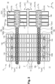
- Figure 2 is a bottom view of the electromechanical system 2 showing first portions 101 of the frame 10, the movable element 13, the transmission devices 14a-14b and the movable electrodes 151-152 of the capacitive detection means 15'.
- Figure 3 is a top view showing only a part of the capacitive detection means 15' (including the first movable electrode 151).
- Figures 4A to 4B are different cross-sectional views of the electromechanical system 2, respectively according to the cross-sectional planes A-Aand C-C represented in Figure 3 . They represent in part of the frame 10, the first transmission device 14a and the capacitive detection means 15'.
- the movable element 13 hereinafter referred to as the piston, is movable in translation relative to the frame 10, in a direction (Z) perpendicular to the plane (XY) of Figure 2 . It preferably comprises a membrane 131 and a rigidifying structure 132 for rigidifying the membrane 131, also referred to as a skeleton or armature.
- the role of the membrane 131 of the piston 13 is to collect, over its entire surface, a pressure difference between its two faces, in order to deduce a variation in atmospheric pressure.
- the membrane 131 of the piston 13 can partly delimit a closed reference volume, where a reference pressure prevails. It separates this reference volume from a cavity open to the outside environment.
- One face of the membrane 131 is therefore subjected to the reference pressure and an opposite face of the membrane 131 is subjected to atmospheric pressure (the variation of which is to be detected in the case of a microphone).
- the reference volume can be quasi-closed, in the sense that there is a trench around the piston (which is cut away). This trench allows the piston to move and allows air to leak between the reference volume and the outside. This leakage is small so that pressures can equalise slowly, filtering out only low-frequency pressure variations.
- the first zone 11 encompasses the cavity open to the outside environment, subjected to atmospheric pressure, and the reference volume subjected to the reference pressure.
- the capacitive detection means 15' measure the displacement of the piston 13, and therefore the pressure difference between its two faces.
- the first and second movable electrodes 151-152 they comprise at least one fixed electrode (relative to the frame 10), separated from the first movable electrode 151 by a first dielectric medium, and at least one additional fixed electrode, separated from the second movable electrode 152 by a second dielectric medium.
- Each movable electrode and associated fixed electrode(s) form the armatures of one or several capacitors whose capacitance varies as a function of the displacement of the piston 13.
- the fixed electrodes may also be called “counter-electrodes”.
- the first dielectric medium and the second dielectric medium are not solid (but are preferably constituted by a gas or a mixture of gases), so as not to hinder the movement of the movable electrodes 151.
- the second dielectric medium is identical to the first dielectric medium, as the movable electrodes 151-152 are both located in the second zone 12.
- the second zone 12 is a controlled atmosphere chamber to reduce the phenomena of viscous friction and the associated acoustic noise.
- controlled atmosphere chamber we mean a chamber under reduced pressure, typically less than 1000 mbar, and preferably less than 1 mbar. In this way, the second zone 12 is subjected to a pressure well below atmospheric pressure or the reference pressure.
- the first movable electrode 151 advantageously has one or several planes of symmetry, for example a plane parallel to the XZ plane (therefore perpendicular to the first beams 1512a) and another plane parallel to the YZ plane.
- the electromechanical system 2 is therefore particularly compact.
- the substrate is used in particular to produce, by etching, the first elements of the transmission devices 14a-14b (transmission shafts 144a-144b and transmission arms 145a-145b), the lower portions of the counter-electrodes 153-154 and a part of the frame 10.
- the substrate may be made of a semiconductor material, for example silicon.
- the first sacrificial layer is intended to disappear in part during manufacture of the electromechanical system 2 to free the membrane 131 of the piston 13, the membrane 1511 of the movable electrodes 151-152 and the sealed insulating elements 161.
- its thickness defines the distance between the membrane 1511 and the lower portions of the counter-electrodes 153-154 (lower air gap).
- This layer also acts as a stop layer during etching of the substrate, the membrane 152a and the second structural layer (the "MEMS" layer described later).
- the remaining parts of the first sacrificial layer form the annular seals 103, 105 and the lower pillars 104.
- the first sacrificial layer can be constituted by a dielectric material, preferably a silicon nitride or a silicon oxide, for example silicon dioxide (SiO 2 ). Its thickness is, for example, between 100 nm and 10 ⁇ m.
- each movable electrode 151, 152 is fused to the corresponding transmission device 14a, 14b, by growing the second structural layer directly from the substrate, at the location of the pivot hinges 16a, 16b (the first and second sacrificial layers having been opened beforehand).
- the pillars 146 of the transmission devices 14a, 14b are formed during this epitaxial growth.
- Figures 5 and 6 represent a second embodiment of the electromechanical system 2.
- Figure 5 is a bottom view of a part of the electromechanical system 2, similar to Figure 2 .
- Figure 6 is a top view of the same part of the electromechanical system 2.
- This second embodiment differs from the first embodiment mainly in that the electromechanical system 2 comprises two movable elements or pistons, rather than a single one.
- the electromechanical system 2 comprises a first piston 13a and a second piston 13b.
- the first piston 13a is connected, on the one hand, to the first movable electrode 151 by the first transmission device 14a, and, on the other hand, to the second movable electrode 152 by the second transmission device 14b.
- the second piston 13b is connected, on the one hand, to the first movable electrode 151 by the first transmission device 14a and, on the other hand, to the second movable electrode 152 by the second transmission device 14b.
- each transmission device 14a, 14b connects the two pistons 13a-13b to the capacitive detection means 15', and more particularly to the movable electrode 151, 152 associated with said transmission device 14a, 14b.
- the movable electrodes 151-152 in Figure 5 are simply smaller than those in Figure 2 , in order to best represent the two pistons.
- the capacitive detection means 15' can be located between the two pistons 13a-13b.
- Each of the pistons 13a-13b separates a cavity open to the outside from a reference volume.
- the first zone 11 comprises two cavities open to the outside and two reference volumes (which can communicate with each other).
- the second zone 12, which contains the movable electrodes 151-152, is located between the pistons 13a-13b.
- the pistons 13a-13b are subjected to the same pressure difference. They are also mounted so that they can move relative to the frame 10 in the same way, preferably in translation along the third direction Z. The pistons 13a-13b therefore have the same displacement.
- the pistons 13a-13b preferably have the same shape, for example rectangular with rounded corners.
- the dimensions (length, width) of the first piston 13a are equal or substantially equal (to within 5%) to those of the second piston 13b.
- the width of a piston is measured in the first direction X and its length is measured in the second direction Y.
- the two pistons 13a-13b in Figure 5 have the same length (measured in Y) as the single piston 13 in Figure 2 , but a width (measured in X) less than or equal to half that of piston 13.
- the electromechanical system 2 comprising two pistons offers better performance, particularly in terms of sensitivity and resonant frequency, because it offers a better compromise between rigidity and mass than the electromechanical system comprising a single piston ( Figure 2 ).
- the two pistons 13a-13b are smaller than a single piston, they are more rigid, all other things being equal (thickness, rigidifying structure, etc.), and are therefore subject to less deformation. They can be more rigid for the same (cumulative) mass or be lighter for the same level of rigidity, or even lighter while being more rigid.
- the parts of the transmission devices 14a-14b that hold the pistons 13a-13b are shorter (due to the smaller width of the pistons) and can therefore be lightened without reducing their rigidity.
- the pistons 13a-13b are advantageously identical. They can be arranged symmetrically with respect to a plane passing through the movable electrodes 151-152. Similarly, the transmission devices 14a, 14b are preferably symmetrical with respect to this plane.
- the first transmission device 14a is mounted so as to rotate relative to the frame 10 by means of several first pivot hinges 16a.
- at least one of the first pivot hinges 16a is located at the first movable electrode 151, another first pivot hinge 16a is located at a first end of the first transmission device 14a (beyond the first piston 13a) and yet another first pivot hinge 16a is located at a second opposite end of the first transmission device 14a (beyond the second piston 13b).
- each transmission device 14a, 14b comprises:
- the transmission devices 14a and 14b have a lattice structure which enables them to transmit movement with as little deformation as possible, while minimising inertia.
- the first piston 13a and the way in which it is connected to the transmission devices 14a-14b will now be described in more detail. This description applies mutatis mutandis to the second piston 13b.
- the rigidifying structure 132 for the first piston 13a advantageously comprises, on the side of the membrane 131 where the transmission devices 14a-14b are located, a first beam 1321 which extends along the length of the first piston 13a.
- the first beam 1321 can extend along the median line M of the first piston 13a, as represented in Figure 5 , or parallel to this median line M at a distance of less than a quarter of the width of the first piston 13a.
- This first beam 1321 advantageously has the same thickness as the transmission shafts 144a, 144b and the transmission arms 145a, 145b, i.e. a thickness of between 5 ⁇ m and 800 ⁇ m. It is formed at the same time as the transmission shafts and arms, by etching the substrate.
- the rigidifying structure 132 for the first piston 13a advantageously comprises a second beam 1322 superimposed on the first beam 1321.
- This second beam 1322 has a thickness strictly less than that of the first beam 1321. It can be formed in the second structural layer described above, the thickness of which is between 5 ⁇ m and 50 ⁇ m.
- the second beam 1322 can have a length equal to that of the first beam 1321.
- Figure 7 represents a third embodiment in which the electromechanical system 2 comprises, in addition to the two pistons 13a-13b, a single movable electrode 151 (for example of the type represented by Figure 5 ) and a single transmission device 14a (for example of the type represented by Figure 5 ).
- the transmission devices 14a-14b, and more particularly the transmission shafts 144a-144b, can adopt other geometries.
- the number of transmission arms 145a, 145b may be greater than 3.
- the electromechanical system 2 has been described taking as an example a microphone with capacitive detection comprising one or several pistons 13, 13a-13b each equipped with a membrane 131 subjected on the one hand to atmospheric pressure and on the other hand to a reference pressure.
- the electromechanical system can form other types of capacitive detection transducer, in particular a loudspeaker (sound emitter) or an ultrasound emitter (which are electroacoustic transducers), or even a differential pressure sensor.
- the first face of the membrane 131 (of each piston) is subjected to a first pressure (not necessarily atmospheric pressure) and the second face of the membrane 131 is subjected to a second pressure, different from the first pressure.
- the displacement of the membrane 131, under the effect of the pressure difference, is measured by the capacitive detection means 15'.
- the membrane 131 of the piston is integral with the frame 10 so as to be sealed and the rigidifying structure 132 of the piston is absent or reduced so as not to anchor it to the frame.
- capacitive actuation means replace the capacitive detection means 15'.
- These capacitive actuation means also comprise two movable electrodes and at least one counter-electrode per movable electrode. The movable electrodes are moved by an electrostatic force and this movement is transmitted by the transmission devices 14a, 14b to the piston 13 or pistons 13a-13b. The movement of the membrane 131 of the piston or pistons 13, 13a-13b enables sound (or ultrasound) to be emitted.
- the second zone 12 may comprise two chambers under a controlled atmosphere, one containing the first movable electrode 151, the other containing the second movable electrode 152.
- the first and second sealed zones 11-12 are not necessarily subjected to different pressures.
- the first zone 11 may also be an aggressive environment and the movable electrodes of the capacitive means (of detection or actuation) are placed in the second zone 12 to protect them from this aggressive environment (in addition to reducing viscous friction, and therefore acoustic noise).
Landscapes
- Engineering & Computer Science (AREA)
- Physics & Mathematics (AREA)
- Signal Processing (AREA)
- Acoustics & Sound (AREA)
- General Physics & Mathematics (AREA)
- Computer Hardware Design (AREA)
- Nanotechnology (AREA)
- Microelectronics & Electronic Packaging (AREA)
- Chemical & Material Sciences (AREA)
- Crystallography & Structural Chemistry (AREA)
- Health & Medical Sciences (AREA)
- Molecular Biology (AREA)
- Power Engineering (AREA)
- General Health & Medical Sciences (AREA)
- Life Sciences & Earth Sciences (AREA)
- Micromachines (AREA)
- Transmission And Conversion Of Sensor Element Output (AREA)
Applications Claiming Priority (1)
| Application Number | Priority Date | Filing Date | Title |
|---|---|---|---|
| FR2315317 | 2023-12-26 |
Publications (1)
| Publication Number | Publication Date |
|---|---|
| EP4578822A1 true EP4578822A1 (de) | 2025-07-02 |
Family
ID=90720854
Family Applications (1)
| Application Number | Title | Priority Date | Filing Date |
|---|---|---|---|
| EP24223160.3A Pending EP4578822A1 (de) | 2023-12-26 | 2024-12-24 | Elektromechanisches system mit zwei beweglichen elementen und kapazitiven mess- oder betätigungsmitteln |
Country Status (3)
| Country | Link |
|---|---|
| US (1) | US20250211919A1 (de) |
| EP (1) | EP4578822A1 (de) |
| CN (1) | CN120213280A (de) |
Citations (5)
| Publication number | Priority date | Publication date | Assignee | Title |
|---|---|---|---|---|
| EP2541222A1 (de) * | 2011-07-01 | 2013-01-02 | Commissariat à l'Énergie Atomique et aux Énergies Alternatives | Druckmessgerät mit optimierter Emfpindlichkeit |
| EP2921836A1 (de) * | 2014-03-19 | 2015-09-23 | Commissariat à l'Énergie Atomique et aux Énergies Alternatives | Sensor zum Messen des mikroelektromechanischen und/oder nanoelektromechanischen Differentialdrucks |
| FR3059659B1 (fr) | 2016-12-07 | 2019-05-17 | Commissariat A L'energie Atomique Et Aux Energies Alternatives | Dispositif de transmission d'un mouvement et d'une force entre deux zones isolees l'une de l'autre |
| EP3766829A1 (de) * | 2019-07-18 | 2021-01-20 | Commissariat à l'Energie Atomique et aux Energies Alternatives | Mechanische verbindung für mems- und nems-vorrichtungen zum messen einer druckveränderung und vorrichtung, die eine solche mechanische verbindung umfasst |
| FR3114584B1 (fr) | 2020-09-29 | 2022-09-16 | Commissariat Energie Atomique | Procédé de fabrication d’un transducteur électroacoustique |
-
2024
- 2024-12-23 US US18/999,173 patent/US20250211919A1/en active Pending
- 2024-12-24 EP EP24223160.3A patent/EP4578822A1/de active Pending
- 2024-12-26 CN CN202411941036.XA patent/CN120213280A/zh active Pending
Patent Citations (5)
| Publication number | Priority date | Publication date | Assignee | Title |
|---|---|---|---|---|
| EP2541222A1 (de) * | 2011-07-01 | 2013-01-02 | Commissariat à l'Énergie Atomique et aux Énergies Alternatives | Druckmessgerät mit optimierter Emfpindlichkeit |
| EP2921836A1 (de) * | 2014-03-19 | 2015-09-23 | Commissariat à l'Énergie Atomique et aux Énergies Alternatives | Sensor zum Messen des mikroelektromechanischen und/oder nanoelektromechanischen Differentialdrucks |
| FR3059659B1 (fr) | 2016-12-07 | 2019-05-17 | Commissariat A L'energie Atomique Et Aux Energies Alternatives | Dispositif de transmission d'un mouvement et d'une force entre deux zones isolees l'une de l'autre |
| EP3766829A1 (de) * | 2019-07-18 | 2021-01-20 | Commissariat à l'Energie Atomique et aux Energies Alternatives | Mechanische verbindung für mems- und nems-vorrichtungen zum messen einer druckveränderung und vorrichtung, die eine solche mechanische verbindung umfasst |
| FR3114584B1 (fr) | 2020-09-29 | 2022-09-16 | Commissariat Energie Atomique | Procédé de fabrication d’un transducteur électroacoustique |
Also Published As
| Publication number | Publication date |
|---|---|
| US20250211919A1 (en) | 2025-06-26 |
| CN120213280A (zh) | 2025-06-27 |
Similar Documents
| Publication | Publication Date | Title |
|---|---|---|
| JP5825899B2 (ja) | マイクロホン製造に特に応用する、mems動的圧力センサー | |
| Esashi et al. | Vacuum-sealed silicon micromachined pressure sensors | |
| US8818007B2 (en) | MEMS-type pressure pulse generator | |
| US8374371B2 (en) | Miniature non-directional microphone | |
| US10807858B2 (en) | Device for transmitting a movement and a force between two zones that are insulated from one another | |
| US11337016B2 (en) | Mechanical connection for a MEMS and NEMS device for measuring a variation in pressure, and device comprising such a mechanical connection | |
| KR20170017788A (ko) | 펌핑 스피커를 위한 시스템 및 방법 | |
| CN107110731B (zh) | 具有改进的操作的动态压力传感器 | |
| CN103518138A (zh) | 一种惯性传感器的制造方法 | |
| Miani et al. | Resonant accelerometers based on nanomechanical piezoresistive transduction | |
| WO2005043173A1 (en) | Trapped charge field bias vibrating beam accelerometer | |
| CN114339558A (zh) | 制造电声换能器的方法 | |
| US20210292158A1 (en) | Microelectromechanical microphone with reduced overall size | |
| EP4578822A1 (de) | Elektromechanisches system mit zwei beweglichen elementen und kapazitiven mess- oder betätigungsmitteln | |
| US20240223967A1 (en) | Electromechanical system comprising capacitive measurement or actuation means | |
| EP4674806A1 (de) | Elektromechanisches system mit zwei benachbarten beweglichen elementen | |
| Wang et al. | Contamination-insensitive differential capacitive pressure sensors | |
| US12563347B2 (en) | Electromechanical system comprising capacitive measurement or actuation means and a transmission shaft | |
| Kurth et al. | A novel 24-kHz resonant scanner for high-resolution laser display | |
| US20250361138A1 (en) | Electromechanical system comprising a movable element provided with an opening | |
| Ozdogan et al. | A MEMS microphone using repulsive force sensors | |
| CN115931185A (zh) | 一种电容式微机电传感器 | |
| Stemme et al. | A capacitively excited and detected resonant pressure sensor with temperature compensation | |
| Okandan et al. | Optical microphone structures fabricated for broad bandwidth and low noise | |
| Bourouina et al. | Preliminary results on a silicon gyrometer based on acoustic mode coupling in small cavities |
Legal Events
| Date | Code | Title | Description |
|---|---|---|---|
| PUAI | Public reference made under article 153(3) epc to a published international application that has entered the european phase |
Free format text: ORIGINAL CODE: 0009012 |
|
| STAA | Information on the status of an ep patent application or granted ep patent |
Free format text: STATUS: REQUEST FOR EXAMINATION WAS MADE |
|
| 17P | Request for examination filed |
Effective date: 20241224 |
|
| AK | Designated contracting states |
Kind code of ref document: A1 Designated state(s): AL AT BE BG CH CY CZ DE DK EE ES FI FR GB GR HR HU IE IS IT LI LT LU LV MC ME MK MT NL NO PL PT RO RS SE SI SK SM TR |