EP4578832A1 - Wasserbehandlungseinheit - Google Patents
Wasserbehandlungseinheit Download PDFInfo
- Publication number
- EP4578832A1 EP4578832A1 EP24217576.8A EP24217576A EP4578832A1 EP 4578832 A1 EP4578832 A1 EP 4578832A1 EP 24217576 A EP24217576 A EP 24217576A EP 4578832 A1 EP4578832 A1 EP 4578832A1
- Authority
- EP
- European Patent Office
- Prior art keywords
- container
- water
- treatment unit
- water treatment
- magnet
- Prior art date
- Legal status (The legal status is an assumption and is not a legal conclusion. Google has not performed a legal analysis and makes no representation as to the accuracy of the status listed.)
- Pending
Links
Images


Classifications
-
- C—CHEMISTRY; METALLURGY
- C02—TREATMENT OF WATER, WASTE WATER, SEWAGE, OR SLUDGE
- C02F—TREATMENT OF WATER, WASTE WATER, SEWAGE, OR SLUDGE
- C02F1/00—Treatment of water, waste water, or sewage
- C02F1/46—Treatment of water, waste water, or sewage by electrochemical methods
- C02F1/461—Treatment of water, waste water, or sewage by electrochemical methods by electrolysis
- C02F1/46104—Devices therefor; Their operating or servicing
- C02F1/46109—Electrodes
-
- C—CHEMISTRY; METALLURGY
- C02—TREATMENT OF WATER, WASTE WATER, SEWAGE, OR SLUDGE
- C02F—TREATMENT OF WATER, WASTE WATER, SEWAGE, OR SLUDGE
- C02F1/00—Treatment of water, waste water, or sewage
- C02F1/46—Treatment of water, waste water, or sewage by electrochemical methods
- C02F1/461—Treatment of water, waste water, or sewage by electrochemical methods by electrolysis
- C02F1/463—Treatment of water, waste water, or sewage by electrochemical methods by electrolysis by electrocoagulation
-
- B—PERFORMING OPERATIONS; TRANSPORTING
- B03—SEPARATION OF SOLID MATERIALS USING LIQUIDS OR USING PNEUMATIC TABLES OR JIGS; MAGNETIC OR ELECTROSTATIC SEPARATION OF SOLID MATERIALS FROM SOLID MATERIALS OR FLUIDS; SEPARATION BY HIGH-VOLTAGE ELECTRIC FIELDS
- B03C—MAGNETIC OR ELECTROSTATIC SEPARATION OF SOLID MATERIALS FROM SOLID MATERIALS OR FLUIDS; SEPARATION BY HIGH-VOLTAGE ELECTRIC FIELDS
- B03C1/00—Magnetic separation
- B03C1/02—Magnetic separation acting directly on the substance being separated
-
- B—PERFORMING OPERATIONS; TRANSPORTING
- B03—SEPARATION OF SOLID MATERIALS USING LIQUIDS OR USING PNEUMATIC TABLES OR JIGS; MAGNETIC OR ELECTROSTATIC SEPARATION OF SOLID MATERIALS FROM SOLID MATERIALS OR FLUIDS; SEPARATION BY HIGH-VOLTAGE ELECTRIC FIELDS
- B03C—MAGNETIC OR ELECTROSTATIC SEPARATION OF SOLID MATERIALS FROM SOLID MATERIALS OR FLUIDS; SEPARATION BY HIGH-VOLTAGE ELECTRIC FIELDS
- B03C1/00—Magnetic separation
- B03C1/02—Magnetic separation acting directly on the substance being separated
- B03C1/025—High gradient magnetic separators
- B03C1/031—Component parts; Auxiliary operations
- B03C1/033—Component parts; Auxiliary operations characterised by the magnetic circuit
- B03C1/0332—Component parts; Auxiliary operations characterised by the magnetic circuit using permanent magnets
-
- B—PERFORMING OPERATIONS; TRANSPORTING
- B03—SEPARATION OF SOLID MATERIALS USING LIQUIDS OR USING PNEUMATIC TABLES OR JIGS; MAGNETIC OR ELECTROSTATIC SEPARATION OF SOLID MATERIALS FROM SOLID MATERIALS OR FLUIDS; SEPARATION BY HIGH-VOLTAGE ELECTRIC FIELDS
- B03C—MAGNETIC OR ELECTROSTATIC SEPARATION OF SOLID MATERIALS FROM SOLID MATERIALS OR FLUIDS; SEPARATION BY HIGH-VOLTAGE ELECTRIC FIELDS
- B03C1/00—Magnetic separation
- B03C1/02—Magnetic separation acting directly on the substance being separated
- B03C1/28—Magnetic plugs and dipsticks
- B03C1/288—Magnetic plugs and dipsticks disposed at the outer circumference of a recipient
-
- C—CHEMISTRY; METALLURGY
- C02—TREATMENT OF WATER, WASTE WATER, SEWAGE, OR SLUDGE
- C02F—TREATMENT OF WATER, WASTE WATER, SEWAGE, OR SLUDGE
- C02F1/00—Treatment of water, waste water, or sewage
- C02F1/001—Processes for the treatment of water whereby the filtration technique is of importance
-
- C—CHEMISTRY; METALLURGY
- C02—TREATMENT OF WATER, WASTE WATER, SEWAGE, OR SLUDGE
- C02F—TREATMENT OF WATER, WASTE WATER, SEWAGE, OR SLUDGE
- C02F1/00—Treatment of water, waste water, or sewage
- C02F1/001—Processes for the treatment of water whereby the filtration technique is of importance
- C02F1/004—Processes for the treatment of water whereby the filtration technique is of importance using large scale industrial sized filters
-
- C—CHEMISTRY; METALLURGY
- C02—TREATMENT OF WATER, WASTE WATER, SEWAGE, OR SLUDGE
- C02F—TREATMENT OF WATER, WASTE WATER, SEWAGE, OR SLUDGE
- C02F1/00—Treatment of water, waste water, or sewage
- C02F1/20—Treatment of water, waste water, or sewage by degassing, i.e. liberation of dissolved gases
-
- C—CHEMISTRY; METALLURGY
- C02—TREATMENT OF WATER, WASTE WATER, SEWAGE, OR SLUDGE
- C02F—TREATMENT OF WATER, WASTE WATER, SEWAGE, OR SLUDGE
- C02F1/00—Treatment of water, waste water, or sewage
- C02F1/46—Treatment of water, waste water, or sewage by electrochemical methods
- C02F1/461—Treatment of water, waste water, or sewage by electrochemical methods by electrolysis
- C02F1/46104—Devices therefor; Their operating or servicing
- C02F1/46176—Galvanic cells
-
- C—CHEMISTRY; METALLURGY
- C02—TREATMENT OF WATER, WASTE WATER, SEWAGE, OR SLUDGE
- C02F—TREATMENT OF WATER, WASTE WATER, SEWAGE, OR SLUDGE
- C02F1/00—Treatment of water, waste water, or sewage
- C02F1/48—Treatment of water, waste water, or sewage with magnetic or electric fields
-
- C—CHEMISTRY; METALLURGY
- C02—TREATMENT OF WATER, WASTE WATER, SEWAGE, OR SLUDGE
- C02F—TREATMENT OF WATER, WASTE WATER, SEWAGE, OR SLUDGE
- C02F1/00—Treatment of water, waste water, or sewage
- C02F1/48—Treatment of water, waste water, or sewage with magnetic or electric fields
- C02F1/481—Treatment of water, waste water, or sewage with magnetic or electric fields using permanent magnets
-
- C—CHEMISTRY; METALLURGY
- C02—TREATMENT OF WATER, WASTE WATER, SEWAGE, OR SLUDGE
- C02F—TREATMENT OF WATER, WASTE WATER, SEWAGE, OR SLUDGE
- C02F1/00—Treatment of water, waste water, or sewage
- C02F1/48—Treatment of water, waste water, or sewage with magnetic or electric fields
- C02F1/488—Treatment of water, waste water, or sewage with magnetic or electric fields for separation of magnetic materials, e.g. magnetic flocculation
-
- C—CHEMISTRY; METALLURGY
- C02—TREATMENT OF WATER, WASTE WATER, SEWAGE, OR SLUDGE
- C02F—TREATMENT OF WATER, WASTE WATER, SEWAGE, OR SLUDGE
- C02F1/00—Treatment of water, waste water, or sewage
- C02F1/58—Treatment of water, waste water, or sewage by removing specified dissolved compounds
-
- C—CHEMISTRY; METALLURGY
- C02—TREATMENT OF WATER, WASTE WATER, SEWAGE, OR SLUDGE
- C02F—TREATMENT OF WATER, WASTE WATER, SEWAGE, OR SLUDGE
- C02F1/00—Treatment of water, waste water, or sewage
- C02F1/58—Treatment of water, waste water, or sewage by removing specified dissolved compounds
- C02F1/62—Heavy metal compounds
- C02F1/64—Heavy metal compounds of iron or manganese
-
- C—CHEMISTRY; METALLURGY
- C23—COATING METALLIC MATERIAL; COATING MATERIAL WITH METALLIC MATERIAL; CHEMICAL SURFACE TREATMENT; DIFFUSION TREATMENT OF METALLIC MATERIAL; COATING BY VACUUM EVAPORATION, BY SPUTTERING, BY ION IMPLANTATION OR BY CHEMICAL VAPOUR DEPOSITION, IN GENERAL; INHIBITING CORROSION OF METALLIC MATERIAL OR INCRUSTATION IN GENERAL
- C23F—NON-MECHANICAL REMOVAL OF METALLIC MATERIAL FROM SURFACE; INHIBITING CORROSION OF METALLIC MATERIAL OR INCRUSTATION IN GENERAL; MULTI-STEP PROCESSES FOR SURFACE TREATMENT OF METALLIC MATERIAL INVOLVING AT LEAST ONE PROCESS PROVIDED FOR IN CLASS C23 AND AT LEAST ONE PROCESS COVERED BY SUBCLASS C21D OR C22F OR CLASS C25
- C23F13/00—Inhibiting corrosion of metals by anodic or cathodic protection
- C23F13/005—Anodic protection
-
- C—CHEMISTRY; METALLURGY
- C23—COATING METALLIC MATERIAL; COATING MATERIAL WITH METALLIC MATERIAL; CHEMICAL SURFACE TREATMENT; DIFFUSION TREATMENT OF METALLIC MATERIAL; COATING BY VACUUM EVAPORATION, BY SPUTTERING, BY ION IMPLANTATION OR BY CHEMICAL VAPOUR DEPOSITION, IN GENERAL; INHIBITING CORROSION OF METALLIC MATERIAL OR INCRUSTATION IN GENERAL
- C23F—NON-MECHANICAL REMOVAL OF METALLIC MATERIAL FROM SURFACE; INHIBITING CORROSION OF METALLIC MATERIAL OR INCRUSTATION IN GENERAL; MULTI-STEP PROCESSES FOR SURFACE TREATMENT OF METALLIC MATERIAL INVOLVING AT LEAST ONE PROCESS PROVIDED FOR IN CLASS C23 AND AT LEAST ONE PROCESS COVERED BY SUBCLASS C21D OR C22F OR CLASS C25
- C23F13/00—Inhibiting corrosion of metals by anodic or cathodic protection
- C23F13/02—Inhibiting corrosion of metals by anodic or cathodic protection cathodic; Selection of conditions, parameters or procedures for cathodic protection, e.g. of electrical conditions
- C23F13/06—Constructional parts, or assemblies of cathodic-protection apparatus
- C23F13/08—Electrodes specially adapted for inhibiting corrosion by cathodic protection; Manufacture thereof; Conducting electric current thereto
- C23F13/12—Electrodes characterised by the material
- C23F13/14—Material for sacrificial anodes
-
- C—CHEMISTRY; METALLURGY
- C02—TREATMENT OF WATER, WASTE WATER, SEWAGE, OR SLUDGE
- C02F—TREATMENT OF WATER, WASTE WATER, SEWAGE, OR SLUDGE
- C02F1/00—Treatment of water, waste water, or sewage
- C02F1/46—Treatment of water, waste water, or sewage by electrochemical methods
- C02F1/461—Treatment of water, waste water, or sewage by electrochemical methods by electrolysis
- C02F1/46104—Devices therefor; Their operating or servicing
- C02F1/46109—Electrodes
- C02F2001/46133—Electrodes characterised by the material
-
- C—CHEMISTRY; METALLURGY
- C02—TREATMENT OF WATER, WASTE WATER, SEWAGE, OR SLUDGE
- C02F—TREATMENT OF WATER, WASTE WATER, SEWAGE, OR SLUDGE
- C02F2101/00—Nature of the contaminant
- C02F2101/10—Inorganic compounds
- C02F2101/20—Heavy metals or heavy metal compounds
- C02F2101/203—Iron or iron compound
-
- C—CHEMISTRY; METALLURGY
- C02—TREATMENT OF WATER, WASTE WATER, SEWAGE, OR SLUDGE
- C02F—TREATMENT OF WATER, WASTE WATER, SEWAGE, OR SLUDGE
- C02F2101/00—Nature of the contaminant
- C02F2101/30—Organic compounds
-
- C—CHEMISTRY; METALLURGY
- C02—TREATMENT OF WATER, WASTE WATER, SEWAGE, OR SLUDGE
- C02F—TREATMENT OF WATER, WASTE WATER, SEWAGE, OR SLUDGE
- C02F2103/00—Nature of the water, waste water, sewage or sludge to be treated
- C02F2103/02—Non-contaminated water, e.g. for industrial water supply
- C02F2103/023—Water in cooling circuits
-
- C—CHEMISTRY; METALLURGY
- C02—TREATMENT OF WATER, WASTE WATER, SEWAGE, OR SLUDGE
- C02F—TREATMENT OF WATER, WASTE WATER, SEWAGE, OR SLUDGE
- C02F2201/00—Apparatus for treatment of water, waste water or sewage
- C02F2201/002—Construction details of the apparatus
- C02F2201/005—Valves
-
- C—CHEMISTRY; METALLURGY
- C02—TREATMENT OF WATER, WASTE WATER, SEWAGE, OR SLUDGE
- C02F—TREATMENT OF WATER, WASTE WATER, SEWAGE, OR SLUDGE
- C02F2201/00—Apparatus for treatment of water, waste water or sewage
- C02F2201/48—Devices for applying magnetic or electric fields
-
- C—CHEMISTRY; METALLURGY
- C02—TREATMENT OF WATER, WASTE WATER, SEWAGE, OR SLUDGE
- C02F—TREATMENT OF WATER, WASTE WATER, SEWAGE, OR SLUDGE
- C02F2301/00—General aspects of water treatment
- C02F2301/02—Fluid flow conditions
- C02F2301/024—Turbulent
-
- C—CHEMISTRY; METALLURGY
- C02—TREATMENT OF WATER, WASTE WATER, SEWAGE, OR SLUDGE
- C02F—TREATMENT OF WATER, WASTE WATER, SEWAGE, OR SLUDGE
- C02F2303/00—Specific treatment goals
- C02F2303/08—Corrosion inhibition
Definitions
- the present invention relates to a water treatment unit for improving the quality of water in a water system.
- a water treatment unit for improving the quality of water in a water system.
- the water treatment unit comprises a container having an inlet and an outlet configured to allow water to flow into and out of the container, respectively, wherein the outlet is located above the inlet, a magnet configured to attract ferrous particles and retain ferrous particles to remove the ferrous particles from the water flowing through the container, a sacrificial anode configured to provide cathodic protection and scavenge oxygen from the water flowing through the container, and a filter element configured to remove detritus from the water flowing through the container.
- the magnet, sacrificial anode, and filter element are located within the container.
- the present invention provides an advantageous water treatment unit for cleaning water in a water system and preventing, or at least reducing, corrosion of the water system.
- the sacrificial anode may be configured to provide anodic treatment and as a result provide a cathodic reaction.
- the water treatment unit provides greater resistance against larger ferrous particles and detritus moving through the water treatment unit.
- the larger particles can be collected at the bottom of the water treatment unit to be drained and removed from a water system during maintenance.
- the container may comprise a splitting element that extends across the container and divides the container into an inlet section comprising the inlet and an outlet section comprising the outlet, wherein the splitting element comprises an aperture configured to allow water to flow from the inlet section of the container to the outlet section of the container.
- the sacrificial anode may be located in the outlet section of the container.
- the sacrificial anode may be located downstream of the at least one magnet. Therefore, the ferrous particles have already been removed from the flow of water and cannot damage the sacrificial anode. Furthermore, all water must pass by the sacrificial anode before it can exit the water treatment unit. Thus, most of the oxygen can be removed from the water in the water treatment unit.
- the filter element may be located in the outlet section of the container. In some embodiments, the filter element may extend from the splitting element into the outlet section of the container. In some embodiments, the filter element may extend from the splitting element to a top wall of the container. Thus, all water that enters the water treatment unit must pass through the filter element. Therefore, detritus in the flow of water can be prevented from re-entering the water system
- the filter element may be a hollow cylindrical filter element configured such that the water flowing through the container has to pass through the filter element before the water can exit through the outlet.
- the filter element may be formed from a stainless steel mesh.
- the filter element may be electrically connected to the container to increase the cathodic surface of the water treatment unit.
- the larger cathodic surface causes a large potential difference with the sacrificial anode.
- the reactions taking place at the sacrificial anode can occur quicker and more oxygen can be removed from the water in the water treatment unit.
- the sacrificial anode may be located within the hollow cylindrical filter element. Thus, any particles that are separated from the sacrificial anode can be prevented from leaving the water treatment unit.
- the sacrificial anode may be located above the aperture in the splitting element. Thus, water flowing through the aperture may be directed directly at the sacrificial anode to ensure the water flowing from the inlet section has its oxygen content removed.
- the sacrificial anode may be an unmeshed anode. In some embodiments, the sacrificial anode may be formed from magnesium.
- the magnet may be located in the inlet section of the container.
- the magnet may be located proximate to the inlet of the container.
- the magnet may be located in a magnet housing.
- the magnet housing may extend into the inlet section of the container from the bottom wall of the container.
- the ferrous particles may be prevented from directly contacting the magnet, which avoids any contact damage.
- the magnet may be easily replaced.
- the magnet or magnet housing may be a flow diverter configured to induce a vortex in the water flowing into the inlet section of the container to improve separation efficiency.
- a water system comprising a water treatment unit according to any one of claim 1 to claim 22.
- Water systems in land and marine installations that are used for heating and/or cooling suffer from adverse effects resulting from poor water quality.
- the quality of the water within a water system is poor, the conditions for corrosion are often present.
- the main conditions that allow for corrosion of elements of a water system to take place include the water having a low pH, the water having a high oxygen content, and water containing a high amount of minerals that lead to a high conductivity.
- the magnet housing 36 may further comprise a cap 39.
- the cap 39 may be configured to close the end of the body 37 of the magnet housing 36 located outside of the container 3.
- the cap 39 may be configured to retain the magnet 7 in the magnet housing 36, during use.
- the cap 39 and body 37 of the magnet housing 36 may comprise complimentary locking features (not shown).
- the magnet 7 When the magnet 7 is housed in the magnet housing 36, the magnet 7 may be removed from the magnet housing 36 which may cause the ferrous particles on the magnet housing 36 to fall into the water in the container 3.
- the magnet 7 may be removed from the magnet housing 36 by an operator pulling on a handle (not shown) located on one end of the magnet 7 closest to the opening of the aperture 38 of the magnet housing 36.
- the magnet 8 may have a strength of at least 35. That is, the maximum energy product or BHmax represented in Mega Gauss Oersteds (MGOe) may be at least 35 or 35 kgf. In some embodiments, the magnet 8 may have a strength of at least 45. That is, the maximum energy product or BHmax represented in Mega Gauss Oersteds (MGOe) may be at least 45 or 45 kgf.
- the water treatment unit 1 may further comprise a drain 41.
- the drain 41 may be located in the bottom wall 23 of the container 3. That is, the drain 41 may comprise an aperture 42 in the bottom wall 23 of the container 3.
- the drain 41 may comprise a drain pipe 43 and a drain valve 44.
- the drain pipe 43 may be configured to connect the aperture 42 in the bottom wall 23 of the container 3 to an existing drain manifold or pipe.
- the aperture 42 may be generally circular, although it will be appreciated that the aperture 42 may take any shape.
- the drain valve 44 may be located along the drain pipe 43.
- the drain valve 44 may be configured to be opened to allow the container 3 of the water treatment unit 1 to be drained or flushed out.
- the drain valve 44 may be connected to a handle 45.
- the handle 45 may be configured to allow manual opening and closing of the drain valve 44.
- the sacrificial anode 8 is located in the outlet section 33 of the water receiving space 4 inside the container 3. That is, the sacrificial anode 8 may be located on the opposite side of the splitting element 35 to the magnet 7.
- the water treatment unit 1 may comprise a single sacrificial anode 8. However, it will be appreciated that in alternative embodiments, the water treatment unit 1 may comprise a plurality of sacrificial anodes 8.
- the sacrificial anode 8 may be attached to the container 3 of the water treatment unit 1 by a connecting arm 47.
- the connecting arm 37 may be configured to provide an electrical connection between the container 3 of the water treatment unit 1, acting as a cathode, and the sacrificial anode 8.
- the connecting arm 37 may extend vertically downwards from the top wall 22 of the container 3.
- the sacrificial anode 8 may be formed from a metal alloy with a more 'active; voltage than the material of the features of the water system 100 and the water treatment unit 1. That is, the sacrificial anode 8 may have more negative reduction potential or more positive electrode potential than the other components of the water treatment unit 1 and/or water system 100.
- the anode 8 is sacrificial in the sense that the anode material is configured to be consumed during the process of improving the quality of the water that flows through the water treatment unit 1.
- the anode is dissolved in the water, which scavenges oxygen in the water and increases the pH of the water.
- the oxygen in the water is scavenged by reacting with the material of the sacrificial anode 8.
- the products of this reaction provides inorganic salts in the water, which increase the pH of the water.
- the lower oxygen content and higher pH of the water reduces the reactions taking place between the water and components of the water treatment unit 1 and the water system 100.
- the sacrificial anode 8 may be formed from magnesium.
- the sacrificial anode 8 may be formed using high potential magnesium anodes.
- the sacrificial anode 8 may be formed from, for example, but not limited to, a magnesium alloy, aluminium, an aluminium alloy, zinc, or a zinc alloy.
- the corrosion process may be inhibited within the water treatment unit 1 because the oxygen in the water and the water react with the sacrificial anode 8 instead of the iron and steel elements of the water treatment unit 1 and the water system 100 due to the presence of the more 'active' sacrificial anode 8. This reduces the oxygen content of the water. This also produces reaction products, such as, for example, magnesium hydroxide, which increase the pH level of the water and reduces corrosion.
- reaction products such as, for example, magnesium hydroxide
- the use of the magnet 7 and the sacrificial anode 8 may removed minerals and salts from the flow of water, which in turn reduces the electrical conductivity of the water, and this inhibits corrosion.
- the sacrificial anode 8 may be unmeshed. That is, the sacrificial anode 8 may not be surrounded by a mesh.
- An advantage associated with an unmeshed sacrificial anode 8 is that there is less disruption of the flow of water to the sacrificial anode 8.
- a meshed sacrificial anode 8 is not essential because the water treatment unit 1 has a built in filter 9 that may filter out particles and detritus such as any magnesium oxide from the sacrificial anode 8 in the flow of water and prevent the particles and detritus from entering the water system 100.
- the sacrificial anode 8 may be a meshed sacrificial anode 8. That is, the sacrificial anode 8 may be surrounded by a mesh (not shown).
- the mesh may be configured to act as a filter. That is, the mesh may be configured to prevent magnesium oxide formed on the sacrificial anode 8 from entering the flow of water through the water treatment unit 1.
- the water treatment unit 1 may comprise a filter element 9.
- the filter element 9 may be located in the outlet section 33 of the water receiving space 4 of the container 3.
- the filter element 9 may extend from the splitting element 31 up into the outlet section 33 of the container 3.
- the filter element 9 may extend from a surface of the splitting element 31 on the outlet side of the container 3.
- the filter element 9 may also extend to the top wall 22 of the container 3. That is, the filter element 9 may extend along the entire length of the outlet section 33 of the container 3.
- the filter element 9 may be a cylindrical filter element 9. That is, the filter element 9 may extend completely around the central aperture 34 in the splitting element 31. This, the flow of water into the outlet section 33 of the container may not exit the outlet 5 of the container without passing through the filter element 9. Furthermore, the filter element 9 may extend circumferentially around the sacrificial anode 8. Thus, any ferrous particles that are not held by the magnet 8 or loose products resulting from a reaction on the sacrificial anode 8 can be filtered out of the flow of water through the water treatment unit 1 by the filter element 9. Therefore, any material that escapes from the magnet 7 or sacrificial anode 8 can be prevented from exiting the container 3 of the water treatment unit 1 through the outlet 6.
- the filter element 9 may be a hollow cylindrical filter element 9. That is, the filter element 9 may be formed by a filter screen. The filter element 9 may be formed by a 40 um screen. It will be appreciated that in other embodiments the filter element 9 may be formed by a 55 um screen or a 110 um screen. In addition, the filter element 9 may be formed from a stainless steel mesh. That is, in the present embodiment, the filter element 9 may be formed by a cylindrical stainless steel mesh screen that may have apertures capable of filtering detritus out of the flow of water that are larger than 40 um.
- the filter element 9 may comprise a double screen arrangement. That is, the filter element 9 may comprise an internal cylindrical mesh and an outer cylindrical mesh that are concentric with each other.
- the internal and external meshes may have the same or different sized apertures.
- the internal and external meshes may be offset so as to provide even smaller gap sizes.
- the filter element 9 may be electrically connected to the container 3.
- the surface area of the cathode can be increased.
- a higher rate of reaction of particles and gases in the water with the sacrificial anode can be achieved. Consequently, the water treatment unit 1 may provide superior performance in improving the quality of the water flowing through the container 3.
- the water treatment unit 1 may further comprise an air vent 51.
- the air vent 51 may be located in the top wall 22 of the container 3.
- the air vent 51 may extend from the outlet section of the container 3 through the top wall 32 of the container, through any layer of insulation present, and through the housing 2.
- the air vent 51 may be an automatic air vent 51.
- the automatic air vent 51 may be configured to allow gases separated from the flow of water to be vented out of the container 3 when the pressure in the container 3 when the gases reach the automatic air vent 51. That is, the automatic air vent 51 may be configured to open when air reaches it.
- the automatic air vent 51 may be configured to close when water reaches it.
- the air vent 51 may open when the pressure in the container 3 exceeds a predetermined level.
- the air vent 51 may also allow gases created as a product of the water reacting with the sacrificial anode 8 to be vented out of the container 3.
- the gases may be hydrogen. That is, the air vent 51 may be configured to allow gases in the form of micro bubbles to exit the container 3.
- the air vent 51 may comprise a vent pipe 52.
- the vent pipe 52 may comprise a vent valve 53.
- the vent valve 53 may be installed at the end of the vent pipe 52 located outside of the housing 2.
- the vent valve 53 may be an automatic valve configured to open automatically once a predefined pressure threshold has been exceeded.
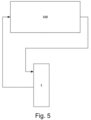
- the water treatment unit 1 can be incorporated into an existing water system 100 or included in a new water system, both schematically represented in Fig. 5 .
- Water from the water system 100 may flow into the container of the water treatment unit 1 via the inlet 5.
- the process of improving the quality of the water in the water system 100 using the water treatment unit 1 will now be described.
- the water When the water enters the inlet 5 to the container 3, the water may impinge on the magnet 7.
- the magnet 7 attracts ferrous particles within the water and holds them, via magnetism, against the magnet housing 36, or magnet 7 where a magnet housing 36 is not present, thus removing the ferrous particles from the flow of water.
- the magnet housing 36, or magnet 7 may be used as a flow diverter. That is, the magnet housing 36, or magnet 7, may be used to direct generally radially flowing water entering the inlet section 32 of the container 3 into a more generally circumferential flow path. Thus, a cyclonic water flow path may be generated. The water then flows inwards towards the aperture 34 in the splitting element 31 and up into the outlet section 33 of the container 3.
Landscapes
- Chemical & Material Sciences (AREA)
- Organic Chemistry (AREA)
- Engineering & Computer Science (AREA)
- Environmental & Geological Engineering (AREA)
- Water Supply & Treatment (AREA)
- Life Sciences & Earth Sciences (AREA)
- Hydrology & Water Resources (AREA)
- Chemical Kinetics & Catalysis (AREA)
- Electrochemistry (AREA)
- General Chemical & Material Sciences (AREA)
- Materials Engineering (AREA)
- Mechanical Engineering (AREA)
- Metallurgy (AREA)
- Analytical Chemistry (AREA)
- Water Treatment By Electricity Or Magnetism (AREA)
Applications Claiming Priority (1)
| Application Number | Priority Date | Filing Date | Title |
|---|---|---|---|
| GB2318519.2A GB2636188A (en) | 2023-12-04 | 2023-12-04 | A water treatment unit |
Publications (1)
| Publication Number | Publication Date |
|---|---|
| EP4578832A1 true EP4578832A1 (de) | 2025-07-02 |
Family
ID=89507744
Family Applications (1)
| Application Number | Title | Priority Date | Filing Date |
|---|---|---|---|
| EP24217576.8A Pending EP4578832A1 (de) | 2023-12-04 | 2024-12-04 | Wasserbehandlungseinheit |
Country Status (3)
| Country | Link |
|---|---|
| US (1) | US20250178932A1 (de) |
| EP (1) | EP4578832A1 (de) |
| GB (1) | GB2636188A (de) |
Citations (1)
| Publication number | Priority date | Publication date | Assignee | Title |
|---|---|---|---|---|
| US20060283783A1 (en) * | 2003-05-29 | 2006-12-21 | Christopher Adey | Separator device |
Family Cites Families (2)
| Publication number | Priority date | Publication date | Assignee | Title |
|---|---|---|---|---|
| KR101700675B1 (ko) * | 2016-10-11 | 2017-01-31 | (주) 디지털워터 | 상수도 적용 가능한 배관 스케일 발생억제 및 제거를 위한 멀티 수처리장치 |
| KR102502379B1 (ko) * | 2022-05-26 | 2023-02-23 | 오주이엔씨(주) | 수처리 장치가 구비된 수도 계량기 |
-
2023
- 2023-12-04 GB GB2318519.2A patent/GB2636188A/en active Pending
-
2024
- 2024-12-04 US US18/968,094 patent/US20250178932A1/en active Pending
- 2024-12-04 EP EP24217576.8A patent/EP4578832A1/de active Pending
Patent Citations (1)
| Publication number | Priority date | Publication date | Assignee | Title |
|---|---|---|---|---|
| US20060283783A1 (en) * | 2003-05-29 | 2006-12-21 | Christopher Adey | Separator device |
Non-Patent Citations (1)
| Title |
|---|
| IWTM: "Protector", 5 May 2020 (2020-05-05), XP093147300, Retrieved from the Internet <URL:https://protektor.no/wp-content/uploads/2021/01/PROTECTOR-DATASHEET-05-05-2020-ENGLISH_compressed.pdf> [retrieved on 20240403] * |
Also Published As
| Publication number | Publication date |
|---|---|
| GB202318519D0 (en) | 2024-01-17 |
| GB2636188A (en) | 2025-06-11 |
| US20250178932A1 (en) | 2025-06-05 |
Similar Documents
| Publication | Publication Date | Title |
|---|---|---|
| US20110048964A1 (en) | Axial-sump electrolytic flow cell | |
| EP2976565B1 (de) | Vorrichtung zur kondensatableitung | |
| GB2491361A (en) | Magnetic filter apparatus | |
| US11014095B2 (en) | Magnetic filter for a central heating system | |
| EP3150266B1 (de) | Festpartikel-fluid-abscheider | |
| EP4458461A1 (de) | Rückgewinnungssystem | |
| EP4397629A1 (de) | Wasserbehandlungseinheit | |
| CN105523611A (zh) | 一种全自动电化学水处理设备 | |
| CN109154483B (zh) | 冷却水循环系统 | |
| BRPI0309525B1 (pt) | "sistema e método de tratamento de água". | |
| US20250178932A1 (en) | Water treatment unit | |
| US20250381571A1 (en) | A water treatment unit | |
| CN214763957U (zh) | 船用气水分离装置 | |
| JP6661966B2 (ja) | 水中不純物分離器及びこれを備える冷却水循環システム | |
| CN211920936U (zh) | 涡流除氧器 | |
| JP2004230264A (ja) | 濾過器 | |
| CN119145008A (zh) | 一种铁悬浮物沉降装置、电解水制氢装置系统及其应用 | |
| JP6345358B1 (ja) | 異物捕捉装置、異物捕捉装置の製造方法および異物捕捉装置を備えた給湯装置 | |
| EP4520729A1 (de) | Wasserbehandlungsvorrichtung mit überwachungs- und steuervorrichtung | |
| KR102702728B1 (ko) | 수처리 장치가 구비된 글로브 밸브 | |
| CN109311708A (zh) | 电气石处理装置以及具有该电气石处理装置的冷却水循环系统 | |
| KR101087706B1 (ko) | 전자장 수처리 장치 | |
| CN208970298U (zh) | 一种油浸式变压器的冷却结构 | |
| CN218339064U (zh) | 水循环管路固液分离器 | |
| AU2021343639B2 (en) | Side stream filter fluid treatment for new and old systems |
Legal Events
| Date | Code | Title | Description |
|---|---|---|---|
| PUAI | Public reference made under article 153(3) epc to a published international application that has entered the european phase |
Free format text: ORIGINAL CODE: 0009012 |
|
| STAA | Information on the status of an ep patent application or granted ep patent |
Free format text: STATUS: THE APPLICATION HAS BEEN PUBLISHED |
|
| AK | Designated contracting states |
Kind code of ref document: A1 Designated state(s): AL AT BE BG CH CY CZ DE DK EE ES FI FR GB GR HR HU IE IS IT LI LT LU LV MC ME MK MT NL NO PL PT RO RS SE SI SK SM TR |
|
| STAA | Information on the status of an ep patent application or granted ep patent |
Free format text: STATUS: REQUEST FOR EXAMINATION WAS MADE |
|
| 17P | Request for examination filed |
Effective date: 20260102 |