EP4579046A1 - Wasserverteilungsnetz und verfahren zum betreiben eines wasserverteilungsnetzes - Google Patents
Wasserverteilungsnetz und verfahren zum betreiben eines wasserverteilungsnetzes Download PDFInfo
- Publication number
- EP4579046A1 EP4579046A1 EP24221223.1A EP24221223A EP4579046A1 EP 4579046 A1 EP4579046 A1 EP 4579046A1 EP 24221223 A EP24221223 A EP 24221223A EP 4579046 A1 EP4579046 A1 EP 4579046A1
- Authority
- EP
- European Patent Office
- Prior art keywords
- water
- network
- sensor
- temperature
- water distribution
- Prior art date
- Legal status (The legal status is an assumption and is not a legal conclusion. Google has not performed a legal analysis and makes no representation as to the accuracy of the status listed.)
- Pending
Links
Images


Classifications
-
- E—FIXED CONSTRUCTIONS
- E03—WATER SUPPLY; SEWERAGE
- E03B—INSTALLATIONS OR METHODS FOR OBTAINING, COLLECTING, OR DISTRIBUTING WATER
- E03B7/00—Water main or service pipe systems
- E03B7/04—Domestic or like local pipe systems
-
- E—FIXED CONSTRUCTIONS
- E03—WATER SUPPLY; SEWERAGE
- E03B—INSTALLATIONS OR METHODS FOR OBTAINING, COLLECTING, OR DISTRIBUTING WATER
- E03B7/00—Water main or service pipe systems
- E03B7/07—Arrangement of devices, e.g. filters, flow controls, measuring devices, siphons or valves, in the pipe systems
- E03B7/074—Arrangement of water treatment devices
-
- E—FIXED CONSTRUCTIONS
- E03—WATER SUPPLY; SEWERAGE
- E03B—INSTALLATIONS OR METHODS FOR OBTAINING, COLLECTING, OR DISTRIBUTING WATER
- E03B7/00—Water main or service pipe systems
- E03B7/07—Arrangement of devices, e.g. filters, flow controls, measuring devices, siphons or valves, in the pipe systems
- E03B7/075—Arrangement of devices for control of pressure or flow rate
-
- E—FIXED CONSTRUCTIONS
- E03—WATER SUPPLY; SEWERAGE
- E03B—INSTALLATIONS OR METHODS FOR OBTAINING, COLLECTING, OR DISTRIBUTING WATER
- E03B7/00—Water main or service pipe systems
- E03B7/07—Arrangement of devices, e.g. filters, flow controls, measuring devices, siphons or valves, in the pipe systems
- E03B7/078—Combined units with different devices; Arrangement of different devices with respect to each other
-
- F—MECHANICAL ENGINEERING; LIGHTING; HEATING; WEAPONS; BLASTING
- F24—HEATING; RANGES; VENTILATING
- F24D—DOMESTIC- OR SPACE-HEATING SYSTEMS, e.g. CENTRAL HEATING SYSTEMS; DOMESTIC HOT-WATER SUPPLY SYSTEMS; ELEMENTS OR COMPONENTS THEREFOR
- F24D17/00—Domestic hot-water supply systems
- F24D17/0073—Arrangements for preventing the occurrence or proliferation of microorganisms in the water
-
- F—MECHANICAL ENGINEERING; LIGHTING; HEATING; WEAPONS; BLASTING
- F24—HEATING; RANGES; VENTILATING
- F24D—DOMESTIC- OR SPACE-HEATING SYSTEMS, e.g. CENTRAL HEATING SYSTEMS; DOMESTIC HOT-WATER SUPPLY SYSTEMS; ELEMENTS OR COMPONENTS THEREFOR
- F24D17/00—Domestic hot-water supply systems
- F24D17/0078—Recirculation systems
-
- F—MECHANICAL ENGINEERING; LIGHTING; HEATING; WEAPONS; BLASTING
- F24—HEATING; RANGES; VENTILATING
- F24D—DOMESTIC- OR SPACE-HEATING SYSTEMS, e.g. CENTRAL HEATING SYSTEMS; DOMESTIC HOT-WATER SUPPLY SYSTEMS; ELEMENTS OR COMPONENTS THEREFOR
- F24D19/00—Details
- F24D19/10—Arrangement or mounting of control or safety devices
- F24D19/1006—Arrangement or mounting of control or safety devices for water heating systems
- F24D19/1051—Arrangement or mounting of control or safety devices for water heating systems for domestic hot water
-
- F—MECHANICAL ENGINEERING; LIGHTING; HEATING; WEAPONS; BLASTING
- F24—HEATING; RANGES; VENTILATING
- F24H—FLUID HEATERS, e.g. WATER OR AIR HEATERS, HAVING HEAT-GENERATING MEANS, e.g. HEAT PUMPS, IN GENERAL
- F24H15/00—Control of fluid heaters
- F24H15/10—Control of fluid heaters characterised by the purpose of the control
- F24H15/14—Cleaning; Sterilising; Preventing contamination by bacteria or microorganisms, e.g. by replacing fluid in tanks or conduits
-
- F—MECHANICAL ENGINEERING; LIGHTING; HEATING; WEAPONS; BLASTING
- F24—HEATING; RANGES; VENTILATING
- F24H—FLUID HEATERS, e.g. WATER OR AIR HEATERS, HAVING HEAT-GENERATING MEANS, e.g. HEAT PUMPS, IN GENERAL
- F24H15/00—Control of fluid heaters
- F24H15/20—Control of fluid heaters characterised by control inputs
- F24H15/212—Temperature of the water
- F24H15/219—Temperature of the water after heating
-
- F—MECHANICAL ENGINEERING; LIGHTING; HEATING; WEAPONS; BLASTING
- F24—HEATING; RANGES; VENTILATING
- F24H—FLUID HEATERS, e.g. WATER OR AIR HEATERS, HAVING HEAT-GENERATING MEANS, e.g. HEAT PUMPS, IN GENERAL
- F24H15/00—Control of fluid heaters
- F24H15/20—Control of fluid heaters characterised by control inputs
- F24H15/238—Flow rate
-
- F—MECHANICAL ENGINEERING; LIGHTING; HEATING; WEAPONS; BLASTING
- F24—HEATING; RANGES; VENTILATING
- F24H—FLUID HEATERS, e.g. WATER OR AIR HEATERS, HAVING HEAT-GENERATING MEANS, e.g. HEAT PUMPS, IN GENERAL
- F24H15/00—Control of fluid heaters
- F24H15/30—Control of fluid heaters characterised by control outputs; characterised by the components to be controlled
- F24H15/305—Control of valves
- F24H15/31—Control of valves of valves having only one inlet port and one outlet port, e.g. flow rate regulating valves
-
- F—MECHANICAL ENGINEERING; LIGHTING; HEATING; WEAPONS; BLASTING
- F24—HEATING; RANGES; VENTILATING
- F24H—FLUID HEATERS, e.g. WATER OR AIR HEATERS, HAVING HEAT-GENERATING MEANS, e.g. HEAT PUMPS, IN GENERAL
- F24H15/00—Control of fluid heaters
- F24H15/30—Control of fluid heaters characterised by control outputs; characterised by the components to be controlled
- F24H15/395—Information to users, e.g. alarms
-
- F—MECHANICAL ENGINEERING; LIGHTING; HEATING; WEAPONS; BLASTING
- F24—HEATING; RANGES; VENTILATING
- F24H—FLUID HEATERS, e.g. WATER OR AIR HEATERS, HAVING HEAT-GENERATING MEANS, e.g. HEAT PUMPS, IN GENERAL
- F24H15/00—Control of fluid heaters
- F24H15/40—Control of fluid heaters characterised by the type of controllers
- F24H15/414—Control of fluid heaters characterised by the type of controllers using electronic processing, e.g. computer-based
-
- F—MECHANICAL ENGINEERING; LIGHTING; HEATING; WEAPONS; BLASTING
- F24—HEATING; RANGES; VENTILATING
- F24D—DOMESTIC- OR SPACE-HEATING SYSTEMS, e.g. CENTRAL HEATING SYSTEMS; DOMESTIC HOT-WATER SUPPLY SYSTEMS; ELEMENTS OR COMPONENTS THEREFOR
- F24D2220/00—Components of central heating installations excluding heat sources
- F24D2220/02—Fluid distribution means
- F24D2220/0264—Hydraulic balancing valves
-
- F—MECHANICAL ENGINEERING; LIGHTING; HEATING; WEAPONS; BLASTING
- F24—HEATING; RANGES; VENTILATING
- F24D—DOMESTIC- OR SPACE-HEATING SYSTEMS, e.g. CENTRAL HEATING SYSTEMS; DOMESTIC HOT-WATER SUPPLY SYSTEMS; ELEMENTS OR COMPONENTS THEREFOR
- F24D2220/00—Components of central heating installations excluding heat sources
- F24D2220/04—Sensors
- F24D2220/042—Temperature sensors
-
- F—MECHANICAL ENGINEERING; LIGHTING; HEATING; WEAPONS; BLASTING
- F24—HEATING; RANGES; VENTILATING
- F24D—DOMESTIC- OR SPACE-HEATING SYSTEMS, e.g. CENTRAL HEATING SYSTEMS; DOMESTIC HOT-WATER SUPPLY SYSTEMS; ELEMENTS OR COMPONENTS THEREFOR
- F24D2220/00—Components of central heating installations excluding heat sources
- F24D2220/04—Sensors
- F24D2220/044—Flow sensors
Definitions
- the present invention relates to the field of water distribution in buildings, the operation of a cold or hot water distribution network and a method of operating the water distribution network for managing hot water. More specifically, the present invention relates to a water distribution network and a method of operating a water distribution network.
- the water distribution network is, for example, a residential building, and more specifically, a hospital or a retirement home. It is also important to ensure good water circulation to limit the proliferation of bacteria in the event of "stagnation" of water in all the pipes of the network. Water temperature below 55°C at low speeds can generate a risk of development of Legionella.
- the water flow rate may vary depending on the complexity of the pipe installation, the number of levels in the building, or the distance between the pipe and the hot water source.
- Water speed and temperature are closely correlated: when the water speed decreases in a branch of the network, the temperature also decreases, increasing the risk of proliferation of bacteria such as Legionella.
- Prior art water temperature measurements involve taking a quantity of water from a pipe in a water distribution network pipeline and measuring the temperature of the taken water to determine the temperature of the water in said water distribution pipeline.
- this method of measuring the water temperature in each pipe is not very accurate because some time has already passed between the water sampling and the water temperature measurement. During this time, the water temperature may drop, resulting in an inaccurate measurement of the water temperature in the pipes of the water distribution network.
- the water circulation in the selected pipe of the water distribution network must be stopped in order to be able to sample the water from the pipe.
- the water circulation of the entire building can be disrupted and the risk of bacteria entering during water sampling is higher.
- each one-off measurement in each pipe in the network is a long process that does not allow for an instant assessment of the status of water circulation and water temperature in the entire water distribution network.
- One of the objects of the present disclosure is to provide a method and system for monitoring water quality, in particular for controlling the risk of water contamination.
- the invention provides a water distribution network comprising: at least one water line extending between a water source outlet and serving at least one loop serving a plurality of water distribution point valves between the water line and a return line, the loop comprising a return pipe downstream of the plurality of water distribution point valves opening into the return line; at least one balancing valve in the return line.
- a plurality of sensors are provided in the water distribution network to obtain current values of water parameters, the water parameters comprising at least the speed and/or the temperature of the water.
- a network monitoring module is provided, adapted to receive current water velocity and/or temperature values from the plurality of sensors, to compare the received current water velocity and/or temperature values with predetermined parameter values to track the status of the water distribution network, and to activate at least one of a display mode to produce at least one display with current values and/or the status of the network, an alert mode to produce an alert on current values and/or the status of the network, and a control mode to send control signals to the at least one balancing valve depending on the current values and/or the status of the network.
- the present invention provides a network for facilitating the monitoring of the status of the water distribution network and providing traceability. This facilitates the management and maintenance of the water distribution network.
- the present invention proposes to monitor the speed to ensure that the water does not stagnate and that the speed complies with the normative requirements. Monitoring the speed makes it possible to ensure that the network balancing is carried out correctly.
- the network comprises a plurality of loops, wherein each loop comprises a conduit for distributing water to the plurality of water distribution point valves via a plurality of the pipes; and a return conduit downstream of the last pipe. opening into the return line, with a balancing valve in the return line. At least one of the sensors is placed in the return line.
- Having the input and return values allows for a comparison to observe temperature or velocity losses across the network as a whole. Additional sensors can be provided in the return line and/or adjacent to the balancing valve to improve monitoring and more accurately identify the state of the network, for example in each of the loops.
- the removable screen allows it to be easily positioned or oriented to facilitate reading of data.
- the network monitoring module is adapted to actuate the at least one balancing valve and/or the at least one temperature regulator if one of the current values of the water parameters is outside a predetermined/preselected range. This allows the network to be maintained even if the user is not on site, or if certain valves are not easily accessible.
- the predetermined/preselected range of one of the current values of the water parameters is the water velocity and/or the water temperature, in particular the predetermined range of velocity is between 0.1 m/s and 2 m/s and the predetermined range of the water temperature is between 20 and 90 degrees, and more particularly between 50 and 80 degrees.
- the speed sensor comprises a first sensor and a second sensor installed on an outer wall of a measuring tube, preferably in a first tubular segment and a second tubular segment respectively, with at least one of the following characteristics: the axis B1' of the first sensor and the axis B2' of the second sensor are substantially perpendicular to the axis A' of the measuring tube; the axis B1' of the first sensor and the axis B2' of the second sensor form an angle with the axis of the measuring tube of between 15° and 75° or an angle formed by the crossing of the axis B1' of the first sensor and the axis B2' of the second sensor is of between 30° and 150°; the first sensor and the second sensor are located substantially on the same axis C1', C2' which form an angle with the axis A' of the measuring tube of between 15° and 75°.
- the first sensor and the second sensor can be installed on the outer wall of the measuring tube fluidly connected to the inlet line, pipeline, conduit or return line by ultrasonic gel.
- ultrasonic gel or coupling resin between the sensors and the surface of the measuring tube can increase the accuracy of water velocity measurements.
- the method comprises actuating by the network monitoring module the at least one balancing valve and/or the at least one temperature controller if one of the current values of the water parameters is outside a predetermined/preselected range.
- the method comprises generating by a network monitoring module an alarm signal if the received values are outside a predetermined/preselected range.
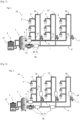
- FIG. 1 illustrates a water distribution network 10 according to the present disclosure.
- the distribution network is a domestic hot water distribution network, typically multi-loop.
- the water distribution point 5 may be a water outlet such as a tap, a thermostatic tap, a shower, located on one or more pipes 9 of the water distribution network 10.
- the temperature of the hot water at outlet 3 of water source 1 is typically between +50°C and +100°C, preferably between +60°C and +90°C and more preferably between +65°C and +75°C. This is only an example of the water temperatures at outlet 3 of water source 1 but other water temperatures can also be provided.
- a first data acquisition module 30 is provided at the outlet of the water source 3, on the water line 4, and a second data acquisition module 30 is provided on the return line 4', at the end of the return line 4'.
- the plurality of sensors 20, 21 makes it possible to obtain current values, also called current values, of water parameters such as water temperature and speed.
- the data acquisition modules 30 By positioning the data acquisition modules 30 in this way, it is possible to obtain at least the values of the inlet and return water parameters of the network 10. If the values obtained at the end of the return line 4' are in an expected range, it can be assumed that the values will also be in an expected range on each loop 18 of the network 10. Having the inlet and return values allows a comparison to be made to observe the temperature or speed losses on the network taken as a whole.
- This arrangement of the data acquisition modules 30 makes it possible to refine the monitoring of the network 10 comprising the plurality of loops 18, some of which are distant from the source of the water 3 and in which the water circulates with a reduced flow rate.
- the water circulates in pipes 11 and the pipelines 9 and passes through a certain number of obstacles called hydraulic members (for example, elbows, fittings, valves)
- the friction and the changes of direction cause losses of water flow rate.
- this involves a reduction in the pressure inside the pipe 11, 11' or a reduction in pressure between the inlet and the outlet of the obstacle or reductions in the sections of the pipelines.
- Knowing the speed and temperature of the water in each 11' return pipe and in the 4' return line is particularly advantageous because it allows for precise monitoring of the state of the water distribution network 10 and better distribution of flow rates or speeds and thus stable temperatures.
- the data acquisition module 30 comprising the sensors 20, 21 may also be located adjacent to one or more water distribution points 5. This position of the sensors 20, 21 makes it possible to measure the temperature and speed of the water which will be distributed to users by one or more water distribution points 5.
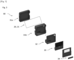
- FIG. 3 illustrates a data acquisition module 30.
- the data acquisition module 30 comprises a housing 31 containing the sensors 20, 21.
- the sensors are located in the same housing 31; they can also be arranged in different housings.
- the housing 31 comprises a first cover 31a and a second cover 31b being configured to cooperate in order to allow the reversible fixing of the housing 31.
- the space formed between the first cover 31a and the second cover 31b comprises the sensors 20, 21.
- the sensors 20, 21 are preferably fixed in an immobile and sealed manner.
- the housing 31 includes a microcontroller 32 which is configured to process the data measured by the temperature sensor 20 and the speed sensor 21, and display the current water speed value and the current water temperature value.
- the housing 31 may include a display 33 or other visual interface or other audible means for displaying or signaling the value of one or more water parameters.
- One or more water parameters and/or the parameters of the data acquisition module 30 may be displayed on the display 33 in response to pressing display buttons 34.
- the screen 33 is preferably removable, so that it can be easily positioned or oriented to facilitate reading of the data.
- the housing 31 comprises the balancing valve 7, and/or the housing 31 is coupled to the balancing valve 7.
- the regulation of the flow rate of the water in the pipe 11, 11' can be managed and actuated by the same housing 31 of the data acquisition module 30.
- the balancing valve 7 being adjacent to the data acquisition module 30 makes it possible to actuate the regulation of the flow rate of the water more quickly.
- the data acquisition module 30 includes a power supply source such as a battery, a cell, or a power supply cable.
- the data acquisition module 30 may include the flow meter reference and/or the water temperature reference and other parameters necessary to calculate the water velocity and/or temperature.
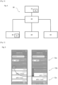
- FIG. 4 illustrates a network monitoring system 80.
- the network monitoring system 80 comprises the monitoring module 70 in communication with the data acquisition modules 30.
- the data acquisition modules 30 are connected to a sensor management module 40 by known communication means such as an Ethernet or POE (Power Over Ethernet) cable, a coaxial cable, an optical fiber, an Internet modem, Wi-Fi, 3G/4G/5G connection, Bluetooth, LIFI, infrared, an SPI link, a DSL cable, a USB cable.
- Ethernet or POE Power Over Ethernet
- the sensor management module 40 is configured to control the measurements taken by the data acquisition modules 30.
- the sensor management module 40 can also be configured to transform the different speeds and the different temperature values obtained by the data acquisition modules 30 into water speed and temperature.
- the sensor management module 40 manages the power supply of the data acquisition modules 30, thus minimizing energy consumption.
- the data acquisition modules 30 are connected to the sensor management module 40 by Bluetooth managed by a communication module 50 as illustrated in Figure 4
- the communication module 50 is configured to enable the data acquisition modules 30 to establish communication with the sensor management module 40 and to transmit the data acquired and calculated by the data acquisition modules 30.
- the sensor management module 40 may also monitor the operation of the data acquisition modules 30 and the communication module 50.
- An interface module 60 is provided to manage physical interactions with the user on the data acquisition module 30 or remotely.
- the interface module 60 also allows the management of the screen 33 of the data acquisition module 30, the control of indicator lights and the waking up of the data acquisition module 30 when display buttons 34 are pressed on the screen 33.
- the plurality of data acquisition modules 30 is connected to at least one aggregator to collect the data acquired by the data acquisition modules 30.
- the one or more aggregators may collect the data from a portion of the water distribution network, for example, a room, a bedroom, a floor or a building.
- the data collected by one or more aggregators are transmitted to a network monitoring module 70 as illustrated in Figure 4 .
- One or more repeaters and/or routers may be present between the plurality of aggregators and the monitoring module 70 and/or the sensor management module 40.
- the connection between the plurality of aggregators may be established by a computer network, such as LAN, WAN, PAN, WAN, or VPN.
- the sensor management module 40 may be connected to the monitoring module 70 or may be integrated with the monitoring module 70.
- the data collected by the aggregator is sent to the router connected to the Internet access. This data is then stored on a “Cloud” type server.
- the server transmits the data containing the information on one or more parameters of the water in the network 10 to the monitoring module 70 via known wireless communication means, such as an Internet modem, Wi-Fi, 3G/4G/5G connection, Bluetooth.
- the monitoring module 70 may be a human-machine interface such as a telephone, a computer, a web page.
- the monitoring module 70 is adapted to receive data from one or more data acquisition modules 30. More specifically, the monitoring module 70 is adapted to receive the current water speed and/or temperature values from the plurality of sensors 20, 21, and to compare the received current water speed and/or temperature values with predetermined parameter values to monitor the state of the water distribution network 10.
- the network monitoring module 70 may activate at least one of the display modes to produce at least one display indicating information on the current values and/or the state of the network, an alert mode to produce an alert on the current values and/or the state of the network.
- the monitoring module 70 may also activate a control mode to send control signals to at least one balancing valve 7.
- the information containing one or more parameters of the water of the water distribution network 10 is displayed on an operating interface 72 of the monitoring module 70, as illustrated in Fig. 5 .
- the operating interface 72 comprises indicators allowing the rapid and comprehensible evaluation of the current state of the water circulating in the pipes 9 and/or in the return pipes 11 and/or in the water line 4 and the return line 4'.
- a first predetermined color 72a is used to indicate that the temperature or velocity of the water in one or more pipes 11 or return pipes 11' has exceeded a minimum threshold or a maximum threshold.
- a second predetermined color 72b is used to signal the absence of the signal from one or more water temperature and/or velocity sensors 20, 21.
- a third predetermined color 72c is used to display that the current water parameters are within the predefined limits.
- the minimum threshold is, for example, a water velocity or water temperature value that is lower than the user-predefined values.
- the user-predefined values can be managed and indicated by parameterization and acquisition software installed in the network monitoring module 70.
- the user can enter the predefined ranges or thresholds via the operating interface 72 of the network monitoring module 70.
- the user can also enter requests such as the actuation of the at least one balancing valve 7 and/or the at least one temperature regulator 12 or modify the measurement parameters of sensors 21, 22.
- the balancing valve 7 presents an obstacle to the flow of water and with the balancing valve 7 partially closed at the end of the loop 18 of the return pipe 11', the flow rate of water is reduced in the loop 18. By opening the balancing valve 7, the flow rate of water is increased.
- the tab color displaying the status of this pipe 11 is then changed to the first predetermined color 72a.
- a notification or a light can be emitted on the operating interface 72 of the network monitoring module 70.
- the maximum threshold is an upper limit of the user-defined values. For example, if the water speed is higher than 3 m/s, a signal or alert will be issued. An audible or visual signal can be emitted on the network management application installed on a telephone device, computer or on a web page to signal the potential problem in the water distribution network 10. This means of displaying information makes it possible to detect the problem linked to the water distribution in advance and without checking in person in a building of the network 10 the current values of the water in each pipe 9 or each pipe 11, 11'.
- the display with different colors has an advantage of directly distinguishing the pipes 9 or the pipes 11, 11' having a problem with the current water parameters or a problem related to an absence of the signal from one of the sensors 20, 21.
- the user can be exempted from manually comparing the current water values with the reference values or from checking each status of each pipe 9 or each pipe 11 since the information is directly displayed and presented in an understandable manner on the operating interface 72 such as a screen of the network monitoring module 70.
- the user can receive notifications such as SMS, emails or messages in the application on the phone or on the computer.
- the parameterization and acquisition software installed in the network monitoring module 70 is also configured to define the current values for the minimum threshold or maximum threshold of water parameters.
- the user can specify the measurement frequencies of the water parameters.
- Certain parameters may have been set, such as, in a non-limiting example, the frequency of the ultrasonic waves, the delay between the excitation of the ultrasonic waves, the number of ultrasonic pulses, the delay between the measurements of the speed or temperature of the water, the calibration factor of the flow rate or temperature of the water compared to the reference values of the flow rate or speed of the water, the frequency of measurements per day or per hour, the amplification of the signal.
- the user can enter the water value limits, acquisition parameter software settings via the operating interface 72, for example, using screen buttons or voice commands.
- the user can choose to ensure that one of the current water values is indeed outside the required limits and measure these current water parameters again. If the current water values remain outside the required limits, the user can actuate manually the valve actuator box to modify the flow rate in the network or in the pipe 11, 11' of the network 10 or operate the temperature regulator 12 to change the temperature of the heating appliance 2.
- the user can ensure that the actuation of the balancing valves 7 has been carried out correctly and check within a time limit whether the current values have returned to the required values. In the event of a breakdown or malfunction of the balancing valve 7, the user being directly on site can correct the detected problems.
- the user may use the parameterization and acquisition software to automatically actuate the valve actuator box and/or the temperature controller 12.
- the valve actuator box triggers one or more balancing valves 7.
- the balancing valve 7 may be positioned at the inlet of one or more pipes 9 and/or the conduit 11 and/or the conduit 11'.
- the parameterization and acquisition software sends control signals to the one or more valve actuator boxes and/or the temperature controller 12 to modify the current water values.
- the user when the water velocity in one of the pipes 11, 11' is less than 0.3 m/s, the user operates the valve actuator box via the configuration and acquisition software.
- the valve actuator box triggers the balancing valve 7 located in the pipe 11 where the water stagnation has been detected by the speed sensor 21.
- the balancing valve 7 increases the flow rate of the water circulating in this pipe 11, 11' in order to regulate the velocity within the water velocity limits required by the user.
- the user can define the water velocity limits between 0.1 m/s and 3 m/s. By measuring the water velocity, it is possible to detect possible areas of water stagnation and dead arms of the network where the water does not circulate. It is also possible to consider increasing the speed of the water circulator 13.
- the regulation of the water temperature can be applied by the temperature regulator 12 if in the pipe 9 or in the pipe 11, 1 1' the water temperature is outside the thresholds defined by the user.
- This management of the current water values remotely makes it possible to control and adjust one of the current water values being outside the defined limits without the physical presence of a specialist who would manually modify the water temperatures of the heating appliance 2 or the flow of water in one or more pipes 11, 11' of the network 10.
- One advantage of automating network monitoring is the modification of current water values in network 10 or in parts of network 10 during hours when a network monitoring professional is not available or would not be readily available, for example, during the night or during the weekend. Regularizing water values in this way is faster than manually operating all or a plurality of balancing or temperature valves in one or more pipes 11 or in one or more pipes 9 being located on several levels of the building, for example.
- Manual actuation proves to be less rapid and efficient due to the greater time required to manually actuate the plurality of balancing valves in the plurality of pipes 11, particularly if it is a complex network.
- Automated actuation can be performed via the human-machine interface of the monitoring module 72 on the plurality or all of the pipes 11, 11' without necessarily being in proximity to the network 10.
- Another advantage of the automation presented in this application is the regulation of the current water values by a user who is not necessarily the boilermaker or pipefitter specialist.
- the regulation of the current water values can be carried out by any user because the current water parameters being higher or lower than the required thresholds are already programmed in the parameterization and acquisition software.
- the user only has to operate one or more pressure and/or temperature regulators using the buttons on the network monitoring module 70 screen if the current water values are outside the programmed limits.
- the regularization of the current water values is performed automatically by the network monitoring module 70 without user intervention whenever one of the current values of the water parameters is outside a predetermined/preselected range.
- Fig. 6 illustrates a method of operating the water distribution network.
- current values of the water parameters are measured (S1) by the plurality of sensors 20, 21.
- the current water speed and/or temperature are determined (S2) from the current values received by the data acquisition module 30.
- the values of the water speed and/or temperature are sent (S3) from the data acquisition module 30 to the network monitoring module 70.
- the values of the speed and/or the temperature of the water are received (S4) by the network monitoring module 70.
- the received water speed and/or temperature values are compared (S5) with parameter values predetermined by the network monitoring module 70.
- At least one predetermined display is produced (S6) based on the comparison between values of the speed and/or temperature of the water received from the data acquisition module 30 and the predetermined values for diagnosing the state of the water distribution network 10.
- the water velocity can be measured by the at least one velocity sensor 21.
- the velocity sensor 21 is, for example, a vane flow meter, an electromagnetic flow meter, a differential pressure flow meter, a vortex flow meter, an ultrasonic flow meter or a Coriolis flow meter. This is only one example of the water velocity sensors, but other water velocity sensors can also be used.
- the ultrasonic flow meter is used.
- One of the advantages of using ultrasonic flow meters to measure water velocity is the absence of direct contact with the water by said flow meter.
- no part of the ultrasonic flow meter is in contact with the water, which is particularly advantageous for maintaining good water quality.
- ultrasonic flow meters there are no moving parts susceptible to wear, which makes the ultrasonic flow meters reliable over time.
- the integration of ultrasonic flow meters does not require changing the tube section which could potentially cause pressure losses.
- the ultrasonic flow meter has high accuracy in measuring water velocity.
- the speed sensor is a flow meter 121 called “Mirrors reflect”.
- the ultrasonic flowmeter (e.g., the velocity sensor 121) is placed in a pipe 11, 11', which may be the inlet line, a pipe 9 or a pipe 11, 11' or the return line 4'.
- a pipe 11' which may be the inlet line, a pipe 9 or a pipe 11, 11' or the return line 4'.
- the sensor is described when placed in a pipe 9.
- the speed sensor 121 comprises at least two sensors - a first sensor 121a and a second sensor 121b.
- the first sensor 121a and the second sensor 121b are placed on a measuring tube 130 having an inlet 130a and an outlet 130b.
- the inlet 130a of the measuring tube 130 is connected to the pipe 9 by known connecting means between the tubes.
- the water enters the measuring tube 130 through the inlet 130a and leaves through the outlet 130b in the same pipe 9 without the flow rate of the water being disturbed or reduced.
- the speed of the water is measured by the speed sensor 121.
- the ultrasounds are first emitted by the first sensor 121a in the direction of the water flow and are received by the second sensor 121b.
- the time traveled T AB between the emission of the ultrasounds and the reception of the ultrasounds in the first case is measured.
- the ultrasounds are emitted by the second sensor 121b and are received by the first sensor 121a.
- the ultrasonic wave is emitted in the second case in the opposite direction to the flow of the water. This ultrasonic wave is “slowed down” by the flow of the water.
- the time traveled T BA between the emission of the ultrasounds and the reception of the ultrasounds in the second case is measured.
- T AB L c + v
- T BA L c ⁇ v
- T AB T BA is the travel time of the ultrasonic waves between the first and second sensors 121a, respectively from A to B and from B to A (in seconds).
- L is the travel length of the ultrasonic waves (in meters)
- c is the speed of the ultrasonic waves in water (in meter/second)
- the order of magnitude of this time difference ⁇ ToF is between 0.5 and 10 ns depending on the configuration and accuracy of the speed sensor 121 and the water speed.
- the travel times T AB , T BA depend essentially on the configuration of the speed sensor 121 such as the position of the sensor, the angle of inclination of the sensors, the material of the tubes.
- the travel times T AB , T BA have very close values with an order of magnitude of the travel times T AB , T BA between 10 and 100 ⁇ s .
- the time difference ⁇ ToF is of small variations (1 ns for example)
- the following approximation can be applied according to equation 4: T AB ⁇ T BA ⁇ T reckon 2
- parameter k in equation (5) is the constant specific to the configuration of the sensor, e.g., topology of the speed sensor 121, the reference of the piezoelectric transducers, the material of the tube, the means of connection of the speed sensor 121 with the tube.
- Water velocity can therefore be determined by measuring the travel times of ultrasonic waves in the direction of water flow and in the opposite direction to water flow.
- the propagation speed of ultrasound in water is known, but this speed of ultrasound is likely to vary with water temperature.
- Equation (5) is also valid for embodiments in which the sensor 121 is immersed in the water tube.
- the measuring tube 130 has a cylindrical body and is made, for example, of plastic or more particularly of polyethylene (PE), crosslinked polyethylene (PER or PEX), polyethylene terephthalate (PET), high density polyethylene (HDPE), medium density polyethylene (MDPE), low density polyethylene (LDPE) or polyvinyl chloride (PVC).
- the material used for the measuring tube 130 is chlorinated polyvinyl chloride (PVC-C or CPVC).
- C-PVC is a material presenting minimal risks of development of a bacterial biofilm on the surface of the measuring tube 130.
- C-PVC is suitable for the chemical treatments recommended by the DGS (Directorate General of Health).
- C-PVC has a high resistance to abrasion in the areas subjected to the mechanical constraints of the flow.
- C-PVC has low thickness and good transmission for ultrasonic waves and these materials are particularly suitable for speed measurements by the ultrasonic sensor.
- the speed sensor 121 comprises two reflecting mirrors 122a and 122b (as shown in FIGS. and figure 8 ).
- the first reflecting mirror 122a is installed in the measuring tube 130 in the direction of water flow.
- the second reflecting mirror 122b is installed in the measuring tube 130 in the opposite direction of water flow.
- the first sensor 121a and the second sensor 121b are installed on a flank or an outer wall of the measuring tube 130 substantially opposite the reflecting mirrors 122a and 122b (the second reflecting mirror 122b not being visible at the figure 8 ).
- Ultrasonic waves are emitted by the first sensor 121a toward the first reflecting mirror 122a positioned at 45 degrees in the direction of water flow.
- the ultrasonic waves are reflected by the first reflecting mirror 122a in the direction of water flow.
- These ultrasonic waves are received by the second reflecting mirror 122b which is positioned at 45 degrees in the opposite direction of water flow.
- the second reflecting mirror 122b reflects these ultrasonic waves toward the second sensor 121b.
- the second reflecting mirror 122b is positioned substantially opposite the first reflecting mirror 122a.
- the first sensor 121a is located on an axis B1' and the second sensor 121b is located on an axis B2'.
- the axis B1' and the axis B2' are substantially perpendicular to the axis of the water flow A'.
- the axis B1' is substantially parallel to the axis B2'.
- the reflecting mirrors 122a and 122b are substantially positioned on the axis of the water flow A'.
- the second sensor 121b also emits the ultrasonic waves toward the second reflecting mirror 122b which reflects these ultrasonic waves toward the first reflecting mirror 122a.
- the first reflecting mirror 122a then reflects these ultrasonic waves toward the first sensor 121a.
- the travel time of the ultrasonic waves in the direction of the water flow and in the direction opposite to the water flow is measured as described above.
- the two sensors 121a, 121b are fixed to the side of the measuring tube 130 by fixing means 123. In one example, these two sensors 121a, 121b are positioned in orifices formed on the side of the measuring tube 130. A seal 124 makes it possible to ensure the sealing of two sensors 121a, 121b positioned in said orifices. Pressing plates 125 are placed on each of two sensors 121a, 121b to immobilize the two sensors 121a, 121b in said orifices. In one example, the two sensors 121a, 121b are fixed between the pressing plates 125 and the measuring tube 130 by screws 123.
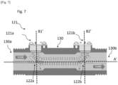
- the speed sensor is a speed sensor 221 called “Reflect”. As described in the first embodiment with the speed sensor 121, the speed sensor 221 with the measuring tube 130 is connected to one or more pipes 9 or conduits 11, 11' of the network 10.
- the first and second sensors 221a, 221b are connected to the side of the measuring tube 130 by the fixing means as described in the first embodiment.
- the axis of rotation of the first tubular segment 230a and the axis of rotation of the second tubular segment 230b correspond substantially to the axes B1', B2' of the two sensors 221a, 221b.
- the first tubular segment 230a is positioned on the side of the measuring tube 130 substantially facing the second tubular segment 230b.
- first and second tubular segments 230a, 230b are formed integrally together with the cylindrical body of the measuring tube 130.
- the first and second tubular segments 230a, 230b are fixed to the measuring tube 130 by the fixing means 135.
- the fixing means 135 are, for example, magnets, a fixing collar, a fixing clip, a fixing glue, a coupling resin or a tube gel for fixing the first and second tubular segments 230a, 230b to the side of the measuring tube 130.
- an ultrasonic gel is used, for example, gels known as couplant B2, couplant D12, couplant H-2, couplant I-2.
- the ultrasonic gel allows the two tubular segments 230a, 230b to be hermetically fixed to the side of the measuring tube 130. The presence of air between the sensors 221a, 221b and the side of the measuring tube 130 can disturb the water velocity measurements.
- Using the ultrasonic gel or the couplant resin between the sensors 221a, 221b and the surface of the measuring tube 130 allows the accuracy of the water velocity measurements to be increased.
- the first and second sensors 221a, 221b have no contact with the water circulating in the measuring tube 130, which makes it possible to maintain good water quality and to avoid water losses.
- the absence of contact with the water makes it possible to keep the flow rate of the water undisturbed by the presence of elements of the sensor such as the reflective mirrors 122a, 122b described in the first embodiment.
- the ultrasonic waves emitted by the first and second sensors 221a, 221b are reflected from the inner surface of the measuring tube 130.
- This inner surface of the measuring tube 130 is opposite the attachment surface of the first and second sensors 221a, 221b.
- the measuring tube 130 may include a reflection rim on the inner surface which is opposite the attachment surface of the first and second sensors 221a, 221b. The reflection rim in the tube allows the best reflection of the ultrasonic waves towards the first and second sensors 221a, 221b.
- the principle of transmitting and receiving ultrasonic waves is the same as described in the first and second embodiments.
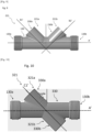
- the first and second sensors 321a, 321b are fixed on the opposite surfaces of a measuring tube 130 as illustrated in Fig. 10 and to the Fig. 11.
- the measuring tube 130 comprises two tubular segments 330a, 330b which are adapted to accommodate the two sensors 321a, 321b on the side of the measuring tube 130, as described in the second embodiment.
- the two tubular segments 330a, 330b are fixed on the two opposite surfaces of the side of the measuring tube 130.
- the first tubular segment 330a is substantially on the same axis C1', C2' as the second tubular segment 330b being opposite the measuring tube 130.
- the axis C1, C2' of two tubular segments 330a, 330b is inclined relative to the axis of the water flow A'.
- the angle of said inclination is the same angle of inclination of the first sensor and the second sensor 321a, 321b relative to the axis of the water flow A'.
- This angle of inclination is between 15 degrees and 75 degrees. In a preferred example this angle is between 45 and 60 degrees ( figures 10 And 11 ).
- the ultrasonic waves emitted by the first sensor 321a pass through the measuring tube 130 and are received by the second sensor 321b.
- the ultrasonic waves emitted by the first sensor 321a are substantially on the same axis as the ultrasonic waves emitted by the second sensor 321b.
- the second sensor 321b also emits the ultrasonic waves toward the first sensor 321a and the travel time of the ultrasonic waves in the direction of water flow and in the direction opposite to the water flow is measured.
- Speed sensor 21, 121, 221, 321 can be used together with temperature sensor 20.
- the temperature sensor 20 can be chosen from the non-limiting list: a thermocouple, a resistance temperature sensor (RTD) or a thermistor (the NTC probe).
- the NTC (negative temperature coefficient) probe or otherwise called NTC probe is used as the temperature sensor 20.
- the resistance decreases with an increase in temperature, thus, by measuring the resistance of the NTC probe, the temperature of the water flowing in the pipe 9 can be determined.
- the NTC probe is an accurate and reliable water temperature measurement result over a given temperature range, with an accuracy of ⁇ 0.5 °C, for example.
- the measurement temperature range is between -10 °C and 100 °C.
- the NTC probe is coupled to the speed sensor, and attached to the speed sensor. This arrangement provides a compact arrangement.
- the CTN probe can be brought into contact with water through an orifice formed on the side of the measuring tube 130.
- the CTN probe can be fixed on the external wall of the measuring tube 130 without direct contact with the water, which makes it possible to maintain good water hygiene.
- the CTN probe is also easy to install in connection with the speed sensor 21 or directly on the measuring tube 130.
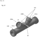
- Fig. 12 describes an example of an integrated module with a temperature sensor 20 and a speed sensor 221.
- the first sensor 221a and the second sensor 221b are positioned according to the second embodiment (“Reflect”).
- the temperature sensor 20 can be isolated from the ambient temperature in order to increase the accuracy of the water temperature measurements.
- the temperature sensor 20 is placed in a sheath 22 fixed to the outer wall of the measuring tube 130.
- the sheath 22 comprising the temperature sensor 20 can be fixed to the outer wall of the measuring tube 130 by known fixing means.
- the temperature sensor 20 is immobilized in the sheath 22 being between the first and second speed sensors 221a, 221b. This position of the sheath 22 allows the stable fixing of the temperature sensor 20 and the easy installation of the temperature sensor 20.
- the water temperature measurements by the temperature sensor 20 can be calibrated according to the material of the measuring tube 130 or according to the dependence of the resistance of the water temperature in the predefined intervals of the water temperature measurement.
- the insulation and/or the position of the temperature sensor 20 may also be taken into account.
- linear calibration is applied for the water temperature measurements.
- the present invention proposes to facilitate the work of monitoring and operating the water distribution network 10, by sensors 20, 21 connected to a monitoring module 70 capable of monitoring the state of the water distribution network, of alerting on the state of the network and/or of reacting to the state of the network.
Landscapes
- Engineering & Computer Science (AREA)
- Physics & Mathematics (AREA)
- General Engineering & Computer Science (AREA)
- Thermal Sciences (AREA)
- Chemical & Material Sciences (AREA)
- Combustion & Propulsion (AREA)
- Mechanical Engineering (AREA)
- Public Health (AREA)
- Health & Medical Sciences (AREA)
- Life Sciences & Earth Sciences (AREA)
- Hydrology & Water Resources (AREA)
- Water Supply & Treatment (AREA)
- Fluid Mechanics (AREA)
- Computer Hardware Design (AREA)
- Arrangements For Transmission Of Measured Signals (AREA)
- Branch Pipes, Bends, And The Like (AREA)
Applications Claiming Priority (1)
| Application Number | Priority Date | Filing Date | Title |
|---|---|---|---|
| FR2315321A FR3157446B1 (fr) | 2023-12-26 | 2023-12-26 | Réseau de distribution d’eau et procédé d'exploitation d'un réseau de distribution d’eau. |
Publications (1)
| Publication Number | Publication Date |
|---|---|
| EP4579046A1 true EP4579046A1 (de) | 2025-07-02 |
Family
ID=91073138
Family Applications (1)
| Application Number | Title | Priority Date | Filing Date |
|---|---|---|---|
| EP24221223.1A Pending EP4579046A1 (de) | 2023-12-26 | 2024-12-18 | Wasserverteilungsnetz und verfahren zum betreiben eines wasserverteilungsnetzes |
Country Status (2)
| Country | Link |
|---|---|
| EP (1) | EP4579046A1 (de) |
| FR (1) | FR3157446B1 (de) |
Citations (4)
| Publication number | Priority date | Publication date | Assignee | Title |
|---|---|---|---|---|
| FR2315321A1 (fr) | 1975-06-24 | 1977-01-21 | Saeby Jernstoberi Maskin | Broyeur dechiqueteur |
| CN103807482A (zh) * | 2012-11-09 | 2014-05-21 | 青岛理工大学琴岛学院 | 家庭供水控制系统 |
| FR3035963A1 (fr) | 2015-05-07 | 2016-11-11 | Sagemcom Energy & Telecom Sas | Dispositif de mesure de vitesse d’un fluide |
| EP3957798A1 (de) * | 2020-08-21 | 2022-02-23 | Wilo Se | Verfahren zum betreiben und/ oder überwachen einer wasserzirkulation |
-
2023
- 2023-12-26 FR FR2315321A patent/FR3157446B1/fr active Active
-
2024
- 2024-12-18 EP EP24221223.1A patent/EP4579046A1/de active Pending
Patent Citations (4)
| Publication number | Priority date | Publication date | Assignee | Title |
|---|---|---|---|---|
| FR2315321A1 (fr) | 1975-06-24 | 1977-01-21 | Saeby Jernstoberi Maskin | Broyeur dechiqueteur |
| CN103807482A (zh) * | 2012-11-09 | 2014-05-21 | 青岛理工大学琴岛学院 | 家庭供水控制系统 |
| FR3035963A1 (fr) | 2015-05-07 | 2016-11-11 | Sagemcom Energy & Telecom Sas | Dispositif de mesure de vitesse d’un fluide |
| EP3957798A1 (de) * | 2020-08-21 | 2022-02-23 | Wilo Se | Verfahren zum betreiben und/ oder überwachen einer wasserzirkulation |
Also Published As
| Publication number | Publication date |
|---|---|
| FR3157446B1 (fr) | 2026-01-16 |
| FR3157446A1 (fr) | 2025-06-27 |
Similar Documents
| Publication | Publication Date | Title |
|---|---|---|
| AU2020291441B2 (en) | Smart water valve | |
| US10969261B2 (en) | Devices and system for channeling and automatic monitoring of fluid flow in fluid distribution systems | |
| US9874466B2 (en) | Methods and apparatus for ultrasonic fluid flow measurement and fluid flow data analysis | |
| US9928724B2 (en) | Flow characteristic detection and automatic flow shutoff | |
| CN208888271U (zh) | 水泄漏检测器以及包括其的供水系统 | |
| CN111771112A (zh) | 建筑供水的被动泄漏检测 | |
| WO2010079311A1 (fr) | Capteur et procédé de mesure en continu du niveau d'encrassement | |
| EP3669148A1 (de) | Durchflussdetektion | |
| CA2954230A1 (fr) | Thermostat connecte temps reel a consigne flottante | |
| US11990023B2 (en) | Method of predicting the risk of a liquid freezing | |
| EP4579046A1 (de) | Wasserverteilungsnetz und verfahren zum betreiben eines wasserverteilungsnetzes | |
| US20240003774A1 (en) | Periodic water leak detection | |
| CN111771111A (zh) | 出口点定位 | |
| BE1026946B1 (fr) | Système de detection de fuite d’eau | |
| US11746508B2 (en) | Control valve | |
| EP3995800B1 (de) | Verfahren zur messung der wassertemperatur in einem zähler | |
| FR2860871A1 (fr) | Procede de detection du disfonctionnement de la derive d'un compteur d'energie thermique et dispositif mettant en oeuvre ledit procede |
Legal Events
| Date | Code | Title | Description |
|---|---|---|---|
| PUAI | Public reference made under article 153(3) epc to a published international application that has entered the european phase |
Free format text: ORIGINAL CODE: 0009012 |
|
| STAA | Information on the status of an ep patent application or granted ep patent |
Free format text: STATUS: THE APPLICATION HAS BEEN PUBLISHED |
|
| AK | Designated contracting states |
Kind code of ref document: A1 Designated state(s): AL AT BE BG CH CY CZ DE DK EE ES FI FR GB GR HR HU IE IS IT LI LT LU LV MC ME MK MT NL NO PL PT RO RS SE SI SK SM TR |
|
| STAA | Information on the status of an ep patent application or granted ep patent |
Free format text: STATUS: REQUEST FOR EXAMINATION WAS MADE |
|
| 17P | Request for examination filed |
Effective date: 20260102 |
|
| RAV | Requested validation state of the european patent: fee paid |
Extension state: MA Effective date: 20260102 Extension state: TN Effective date: 20260102 |
|
| R17P | Request for examination filed (corrected) |
Effective date: 20251231 |
|
| RAV | Requested validation state of the european patent: fee paid |
Extension state: MA Effective date: 20251231 Extension state: TN Effective date: 20251231 |