EP4579054A1 - Charnière pour un dispositif, en particulier pour un appareil ménager ou un meuble, ainsi que dispositif, en particulier appareil ménager ou meuble - Google Patents
Charnière pour un dispositif, en particulier pour un appareil ménager ou un meuble, ainsi que dispositif, en particulier appareil ménager ou meuble Download PDFInfo
- Publication number
- EP4579054A1 EP4579054A1 EP23425069.4A EP23425069A EP4579054A1 EP 4579054 A1 EP4579054 A1 EP 4579054A1 EP 23425069 A EP23425069 A EP 23425069A EP 4579054 A1 EP4579054 A1 EP 4579054A1
- Authority
- EP
- European Patent Office
- Prior art keywords
- hinge
- relative
- transmission
- axis
- transmission part
- Prior art date
- Legal status (The legal status is an assumption and is not a legal conclusion. Google has not performed a legal analysis and makes no representation as to the accuracy of the status listed.)
- Pending
Links
Images


Classifications
-
- E—FIXED CONSTRUCTIONS
- E05—LOCKS; KEYS; WINDOW OR DOOR FITTINGS; SAFES
- E05F—DEVICES FOR MOVING WINGS INTO OPEN OR CLOSED POSITION; CHECKS FOR WINGS; WING FITTINGS NOT OTHERWISE PROVIDED FOR, CONCERNED WITH THE FUNCTIONING OF THE WING
- E05F1/00—Closers or openers for wings, not otherwise provided for in this subclass
- E05F1/08—Closers or openers for wings, not otherwise provided for in this subclass spring-actuated, e.g. for horizontally sliding wings
- E05F1/10—Closers or openers for wings, not otherwise provided for in this subclass spring-actuated, e.g. for horizontally sliding wings for swinging wings, e.g. counterbalance
- E05F1/12—Mechanisms in the shape of hinges or pivots, operated by springs
- E05F1/1246—Mechanisms in the shape of hinges or pivots, operated by springs with a coil spring perpendicular to the pivot axis
- E05F1/1253—Mechanisms in the shape of hinges or pivots, operated by springs with a coil spring perpendicular to the pivot axis with a compression spring
- E05F1/1261—Mechanisms in the shape of hinges or pivots, operated by springs with a coil spring perpendicular to the pivot axis with a compression spring for counterbalancing
-
- E—FIXED CONSTRUCTIONS
- E05—LOCKS; KEYS; WINDOW OR DOOR FITTINGS; SAFES
- E05F—DEVICES FOR MOVING WINGS INTO OPEN OR CLOSED POSITION; CHECKS FOR WINGS; WING FITTINGS NOT OTHERWISE PROVIDED FOR, CONCERNED WITH THE FUNCTIONING OF THE WING
- E05F1/00—Closers or openers for wings, not otherwise provided for in this subclass
- E05F1/08—Closers or openers for wings, not otherwise provided for in this subclass spring-actuated, e.g. for horizontally sliding wings
- E05F1/10—Closers or openers for wings, not otherwise provided for in this subclass spring-actuated, e.g. for horizontally sliding wings for swinging wings, e.g. counterbalance
- E05F1/12—Mechanisms in the shape of hinges or pivots, operated by springs
- E05F1/1246—Mechanisms in the shape of hinges or pivots, operated by springs with a coil spring perpendicular to the pivot axis
- E05F1/1269—Mechanisms in the shape of hinges or pivots, operated by springs with a coil spring perpendicular to the pivot axis with a traction spring
- E05F1/1276—Mechanisms in the shape of hinges or pivots, operated by springs with a coil spring perpendicular to the pivot axis with a traction spring for counterbalancing
-
- E—FIXED CONSTRUCTIONS
- E05—LOCKS; KEYS; WINDOW OR DOOR FITTINGS; SAFES
- E05Y—INDEXING SCHEME ASSOCIATED WITH SUBCLASSES E05D AND E05F, RELATING TO CONSTRUCTION ELEMENTS, ELECTRIC CONTROL, POWER SUPPLY, POWER SIGNAL OR TRANSMISSION, USER INTERFACES, MOUNTING OR COUPLING, DETAILS, ACCESSORIES, AUXILIARY OPERATIONS NOT OTHERWISE PROVIDED FOR, APPLICATION THEREOF
- E05Y2201/00—Constructional elements; Accessories therefor
- E05Y2201/60—Suspension or transmission members; Accessories therefor
- E05Y2201/622—Suspension or transmission members elements
- E05Y2201/624—Arms
-
- E—FIXED CONSTRUCTIONS
- E05—LOCKS; KEYS; WINDOW OR DOOR FITTINGS; SAFES
- E05Y—INDEXING SCHEME ASSOCIATED WITH SUBCLASSES E05D AND E05F, RELATING TO CONSTRUCTION ELEMENTS, ELECTRIC CONTROL, POWER SUPPLY, POWER SIGNAL OR TRANSMISSION, USER INTERFACES, MOUNTING OR COUPLING, DETAILS, ACCESSORIES, AUXILIARY OPERATIONS NOT OTHERWISE PROVIDED FOR, APPLICATION THEREOF
- E05Y2600/00—Mounting or coupling arrangements for elements provided for in this subclass
- E05Y2600/10—Adjustable
-
- E—FIXED CONSTRUCTIONS
- E05—LOCKS; KEYS; WINDOW OR DOOR FITTINGS; SAFES
- E05Y—INDEXING SCHEME ASSOCIATED WITH SUBCLASSES E05D AND E05F, RELATING TO CONSTRUCTION ELEMENTS, ELECTRIC CONTROL, POWER SUPPLY, POWER SIGNAL OR TRANSMISSION, USER INTERFACES, MOUNTING OR COUPLING, DETAILS, ACCESSORIES, AUXILIARY OPERATIONS NOT OTHERWISE PROVIDED FOR, APPLICATION THEREOF
- E05Y2800/00—Details, accessories and auxiliary operations not otherwise provided for
- E05Y2800/26—Form or shape
- E05Y2800/266—Form or shape curved
-
- E—FIXED CONSTRUCTIONS
- E05—LOCKS; KEYS; WINDOW OR DOOR FITTINGS; SAFES
- E05Y—INDEXING SCHEME ASSOCIATED WITH SUBCLASSES E05D AND E05F, RELATING TO CONSTRUCTION ELEMENTS, ELECTRIC CONTROL, POWER SUPPLY, POWER SIGNAL OR TRANSMISSION, USER INTERFACES, MOUNTING OR COUPLING, DETAILS, ACCESSORIES, AUXILIARY OPERATIONS NOT OTHERWISE PROVIDED FOR, APPLICATION THEREOF
- E05Y2800/00—Details, accessories and auxiliary operations not otherwise provided for
- E05Y2800/26—Form or shape
- E05Y2800/292—Form or shape having apertures
- E05Y2800/296—Slots
-
- E—FIXED CONSTRUCTIONS
- E05—LOCKS; KEYS; WINDOW OR DOOR FITTINGS; SAFES
- E05Y—INDEXING SCHEME ASSOCIATED WITH SUBCLASSES E05D AND E05F, RELATING TO CONSTRUCTION ELEMENTS, ELECTRIC CONTROL, POWER SUPPLY, POWER SIGNAL OR TRANSMISSION, USER INTERFACES, MOUNTING OR COUPLING, DETAILS, ACCESSORIES, AUXILIARY OPERATIONS NOT OTHERWISE PROVIDED FOR, APPLICATION THEREOF
- E05Y2900/00—Application of doors, windows, wings or fittings thereof
- E05Y2900/30—Application of doors, windows, wings or fittings thereof for domestic appliances
Definitions
- the present invention relates to a hinge for a device, in particular for a household appliance or a piece of furniture. Furthermore, the invention relates to a device, in particular a household appliance or a piece of furniture, comprising at least one such hinge.
- the respective device has a respective device body, which for example has a receiving space, also referred to as a receiving area.
- the receiving space is, for example, a baking tray, in which case the device is designed, for example, as an oven.
- the receiving space is, for example, a cooking chamber in which food can be cooked.
- the receiving space can be a treatment chamber for washing or rinsing dishes.
- the device further has a door, also referred to as a flap, which is connected in an articulated manner to the respective device body via at least one hinge, usually via at least or exactly two hinges, and is thus held on the respective device body so as to be pivotable relative to the respective device body.
- a door also referred to as a flap
- the object of the present invention is to provide a hinge for a device such as a household appliance or a piece of furniture and a device with to create at least one such hinge so that a particularly advantageous adaptability of the hinge can be realized.
- a first aspect of the invention relates to a hinge for a device.
- the device in its fully manufactured state, has the hinge.
- the device in its fully manufactured state, has a device body, also referred to simply as a base body or body, which can, for example, have a receiving space, also referred to as a receiving area.
- the device for example, in its fully manufactured state, has a door, also referred to as a flap, which is connected to the device body via the hinge, i.e., by means of the hinge.
- the door is held on the device body by means of the hinge so that it can pivot relative to the device body.
- the door can be pivoted relative to the device body while the door is held on the device body by means of the hinge.
- the door can be pivoted relative to the device body between at least one open position and one closed position by means of the hinge.
- the receiving space has an opening, particularly designed as a through-opening, which, for example, opens on the one hand into the receiving space and on the other hand at or into an environment of the device body itself, i.e., considered on its own.
- the closed position for example, at least a partial area of the opening and thus of the receiving space is closed off, in particular from the environment, by the door.
- the door in particular from the environment, and is thus closed off.
- the door releases at least the partial area, so that, for example, in the open position, at least one object can be moved from the environment into the receiving space via the released partial area, or from the receiving space into the environment. can be.
- the receiving space is, for example, a treatment chamber for washing dishes.
- dishes can be moved from the surroundings into the receiving space via the released partial area in order to wash the dishes.
- washed i.e. rinsed
- dishes can be removed from the receiving space via the released partial area in the open position.
- the base element is a component of the device body, in particular of a wall and very particularly of a side wall of the device body.
- the hinge further has a hinge arm, which is also referred to as a pivot arm and is connected to the base element so as to be pivotable about a first pivot axis relative to the base element.
- the hinge arm can be pivoted about the first pivot axis relative to the base element, while the hinge arm is held on the base element, i.e., connected to the base element.
- the base element is connectable or connected at least indirectly, in particular directly, to the device body or to a component of the device body.
- the hinge arm is connectable or connected to the door or to a component of the door.
- the third pivot axis is spaced apart from the first pivot axis, from the axis of rotation and from the second pivot axis.
- the third pivot axis runs parallel to the first pivot axis, parallel to the second pivot axis and parallel to the axis of rotation.
- the first pivot axis, the second pivot axis, the third pivot axis and the axis of rotation are spaced apart from one another when viewed in pairs and preferably run parallel to one another when viewed in parallel.
- a further embodiment is characterized in that the base element has a second guide, in particular in addition to the first guide.
- the transmission element and, with it, the axis of rotation can be displaced in a guided manner along the second guide of the base element and thus relative to the base element.
- the second guide is or defines a second movement path or a second guide track, along which the transmission element and, with it, the axis of rotation can be displaced in a guided manner relative to the base element.
- the second guide defines a second direction of movement, along which the transmission element and the axis of rotation can be displaced in a guided manner relative to the base element or can be displaced in a guided manner when the transmission element and the axis of rotation are displaced along the second guide relative to the base element.
- the second movement path or the second guide track and thus, for example, the second direction of movement run in a straight line, thus along a second straight line of extension.
- the second straight line of extension runs parallel to the first straight line of extension.
- the second movement path or the second guide path runs parallel to the first movement path or the first guide path.
- a further embodiment is characterized in that at least the predominant part, i.e. at least more than half of the spring, in particular the entire spring, is arranged in a lower region of the base element in the installed position of the hinge or is connected to the base element in a vertical direction downwards in the installed position of the hinge.
- This also makes it possible to realize a particularly advantageous, in particular a particularly compact, design of the hinge and/or the hinge can be arranged particularly advantageously in the device body, so that particularly advantageous dimensions of the hinge, in particular of the spring and/or the transmission element, can be realized.
- an advantageous transmission ratio can be realized between the hinge arm and the spring, so that a particularly advantageous operation of the door can be achieved.
- the device of the hinge has a plurality of fixing elements, by means of which the transmission parts (device parts) can be fixed in the positions relative to one another.
- a first of the fixing elements is provided on one of the device parts, wherein a plurality of second of the fixing elements are provided on the other device part.
- the first fixing element is formed integrally with the one device part, so that preferably the first fixing element and the one device part are formed from a single piece.
- a further embodiment is characterized in that the respective second fixing element has a respective receptacle into which the first fixing element can be moved, whereby the first fixing element can be brought into positive engagement with the respective second fixing element and the transmission parts can be fixed in position relative to one another. This allows the hinge to be adapted particularly easily and as needed.
- a base element 24 which can also be used as a carrier element or carrier part and is designed, for example, as a base plate, which is also referred to as a carrier plate.
- the base element 24 is designed separately from the device body 12 and is connected at least indirectly, in particular directly, to the device body 12.
- the device body 12 has two side walls 26 and 28, which are spaced apart from one another in the transverse direction of the device 10 and delimit the receiving space 14 in the transverse direction of the device 10, in particular directly in each case.
- the base element 24 is fastened to the side wall 26, in particular in such a way that relative movements between the side wall 26 and the base element 24 are prevented. It can be seen that the side wall 26 is a component of the device body 12.
- the hinge 20 also has a hinge arm 30, also referred to simply as an arm or pivot arm, which is pivotally connected to the base element 24 about a first pivot axis 32 relative to the base element 24.
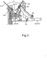
- the pivot axis 32 runs in the transverse direction of the device 10, wherein the hinge 20 assumes its installed position in the fully manufactured state of the device 10 and when the device 10 is in its intended use position, which is Fig. 1 is shown.
- the device 10 In its fully manufactured state, the device 10 has the hinge 20, which is fastened to the side wall 26 in the fully manufactured state of the device 10.
- the door pivot axis is defined by the hinge 20. It is conceivable that the first pivot axis 32 coincides with the door pivot axis or is the door pivot axis.
- the hinge 20 also has a transmission element 34, which is formed in particular separately from the base element 24 and is held on the base element 24 so as to be rotatable about a rotation axis 36 relative to the base element 24.
- the pivot axis 32 and the rotation axis 36 run parallel to one another, wherein the pivot axis 32 and the rotation axis 36 are spaced apart from one another, in particular in the depth direction of the device 10.
- the depth direction of the device 10 is illustrated by a double arrow 38 and runs perpendicular to the transverse direction of the device 10. In the position of use of the In device 10, the depth direction runs horizontally, i.e.
- the receiving space 14 is delimited to the rear by a rear wall 40 of device body 12, in particular directly.
- the receiving space 14 is delimited to the front in the depth direction of device 10 by door 18, in particular directly.
- the receiving space 14 is delimited downwards by a base of device body 12 (not visible in the figures).
- the receiving space 14 is delimited upwards by a ceiling of device body 12 (not visible in the figures).
- the vertical direction of the device 10 is illustrated by a double arrow 42 and runs perpendicular to the depth direction and perpendicular to the transverse direction, wherein in the position of use of the device 10 the vertical direction runs in the vertical direction, i.e. vertically.
- the hinge 20 further comprises a Fig. 2
- the hinge 20 further comprises an actuating element 46 which is coupled to the spring 44.
- the spring 44 has two ends, namely a Fig. 1 recognizable, first end E1 and a second end. The ends of the spring 44 are spaced apart from one another in the longitudinal direction of the spring 44. In the installed position of the hinge 20, the longitudinal direction of the spring 44 runs in the vertical direction, thus in the vertical direction of the device 10.
- the first end E1 in the longitudinal direction of the spring 44 can be or is supported at least indirectly, in particular directly, on a first stop 48 provided on the base element 24, wherein the stop 48 is provided at least indirectly, in particular directly, on the base element 24, in particular in such a way that relative movements between the base element 24 and the stop 48 are avoided, and thus prevented.
- the second end can be or is supported, for example, at least indirectly, in particular directly, on the actuating element 46, in particular on a second stop of the actuating element 46, in the longitudinal direction of the spring 44.
- the ends of the spring 44 and thus the spring 44 in The spring 44 is arranged between the first stop 48 and the second stop in the longitudinal direction of the spring 44.
- the second stop is translationally movable, and therefore displaceable, relative to the first stop 48 in the longitudinal direction of the spring 44, as a result of which the spring 44 can be tensioned and relaxed.
- the spring 44 can be tensioned or tensioned, in this case compressible or compressed and thereby tensioned or tensioned.
- the spring 44 can be relaxed or tensioned and in this case in particular lengthened or elongated, i.e. its length can be increased or increased.
- the spring 44 provides a spring force which acts at least indirectly, in particular directly, on the actuating element 46, in particular via the second stop of the actuating element 46, in particular via the second stop of the actuating element 46.
- the second stop is in Fig. 1 recognizable and labeled 50. Also recognizable in Fig. 1 is the second end of the spring 44, designated E2.
- the base element 24 has a first guide 52.
- the base element 24 can be formed in one piece or in one part, thus from a single piece. Furthermore, it is conceivable that the base element 24 is formed in several parts and thus has several components formed separately from one another and connected to one another.
- the actuating element 46 is articulated with the Transmission element 34 is coupled and can be moved in a guided manner along the first guide 52 of the base element 24, and thus can be moved in a guided translational manner. This means that the actuating element 46 can be moved along the guide 52 of the base element 24 and thus in a guided manner relative to the base element 24.
- the first guide 52 is or comprises a first movement path, which is also referred to as the first guide path.
- the actuating element 46 engages in the first movement path so that the actuating element 46 can be moved in a guided manner along the first movement path and thus relative to the base element 24.
- the first movement path is or defines a first movement direction along which the actuating element 46 can be moved in a guided manner relative to the base element 24.
- the first guide 52 and thus the first movement path and the first movement direction run rectilinearly along a first extension line, which in the present case runs in the vertical direction in the installed position of the hinge 20, i.e., runs vertically.
- the first guide 52 thus extends vertically, so that the first guide 52 is a vertical guide, in particular a vertical sliding guide.
- the spring can be tensioned and relaxed, in particular with respect to the installed position of the hinge 20, and the actuating element 46 is displaced in the vertical direction due to the verticality of the first guide 52, in particular with respect to the installed position of the hinge 20.
- FIG. 2 An arrow 54 illustrates a first direction, which coincides with the first direction of movement or runs parallel to the first direction of movement. Furthermore, an arrow 56 illustrates a second direction, which is opposite to the first direction and coincides with the first direction of movement or runs parallel to the first direction of movement.
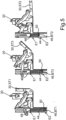
- Fig. 5 It can be seen that the hinge arm 30 is pivotable about the pivot axis 32 between a first pivot position ST1 and a second pivot position ST2 relative to the base element 24.
- the pivot positions ST1 and ST2 of the hinge arm 30 are respective end positions of the hinge arm 30, which can be pivoted into its respective end position relative to the base element 24 about the pivot axis 32, but cannot be pivoted beyond its respective end position about the pivot axis 32 relative to the base element 24.
- Fig. 5 Also shown is a third pivot position ST3 of the hinge arm 30, wherein the third pivot position ST3 lies between the pivot positions ST1 and ST2.
- Fig. 5 shows a first actuating position BT1 of the actuating element 46.
- Fig. 5 a second actuating position BT2 of the actuating element 46.
- the actuating element 46 can be moved from the first actuating position BT1 into the second actuating position BT2 by moving the actuating element 46 along the first guide 52 in the first direction relative to the base element 24 is pushed or shifted.
- the stop 50 is moved towards the stop 48, whereby the spring 44 is tensioned, in this case compressed and tensioned.
- actuating position BT3 of the actuating element 46 wherein the actuating position BT3 lies between the actuating positions BT1 and BT2, in particular such that the third actuating position BT3 lies exactly in the middle between the actuating positions BT1 and BT2.
- the spring force of the spring 44 opposes the displacement of the actuating element 46 from the first actuating position BT1 into the second actuating position BT2.
- the spring force of the spring 44 can cause or at least assist the displacement of the actuating element 46 from the second actuating position BT2 into the first actuating position BT1.
- the total torque has a first torque value
- the total torque has a second torque value
- the total torque has a third torque value.
- the second torque value is greater than the first torque value
- the third torque value is greater than the first torque value and greater than the second torque value, in particular with respect to the respective absolute value of the respective torque value.
- a preload of the spring 44 can be varied by adjusting the respective position and thus by varying the angle ⁇ .
- first fixing element is provided on the transmission part 35, wherein, for example, the connecting element 43 can be inserted through the through-opening of the first fixing element and can thereby be selectively moved, in particular screwed, into the respective second fixing element or into its respective second opening, and thereby fix the transmission parts 35 and 37 relative to one another.
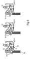
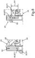
- Fig. 8 shows two schematic side views of the hinge 20 according to the first embodiment.
- Fig. 10 shows a partial schematic side view of the hinge 20, in particular the transmission part 35, which has the control cam (guide track 82).
- Fig. 10 Also shown are different regions BE1 and BE2 of the guideway 82, wherein respective first subregions of the regions BE1 and BE2 overlap each other, and wherein respective second subregions of the regions BE1 and BE2 do not overlap each other. If the door 18 is alternately opened and closed, i.e., the hinge arm 30 is alternately pivoted into the pivot positions ST1 and ST2 while the transmission part 35 is in the position P1, the actuating element 46 moves exclusively in the area BE1 of the guide track 82 with respect to the areas BE1 and BE2.
- the actuating element 46 subsequently moves exclusively in the area BE2 of the guide track 82 with respect to the areas BE1 and BE2.
- the respective area BE1, BE2 is also referred to as the respective working area, in which the spring 44 works, i.e. is relaxed and tensioned and thus, for example, performs work, in particular deformation work.
- the area BE2 resulting from position P3 is larger than the area BE1 resulting from position P1. This means that when the door is opened and closed, and thus when the hinge arm 30 pivots, the spring 44 is tensioned more strongly, thereby increasing the spring force.
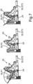
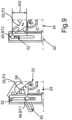
- Fig. 12 shows two schematic side views of the hinge 20, in particular of the transmission element 34.
- the respective first fixing element 41 has a respective receptacle 47.
- a second of the fixing elements is
- a transmission part 37 is provided and designated 45.
- the second fixing element 45 can be moved into the respective receptacle 47, whereby the fixing element 45 can be brought into positive engagement with the respective fixing element 41.
- the transmission parts 35 and 37 can be fixed in the respective positions relative to one another.
Landscapes
- Hinges (AREA)
Priority Applications (1)
| Application Number | Priority Date | Filing Date | Title |
|---|---|---|---|
| EP23425069.4A EP4579054A1 (fr) | 2023-12-28 | 2023-12-28 | Charnière pour un dispositif, en particulier pour un appareil ménager ou un meuble, ainsi que dispositif, en particulier appareil ménager ou meuble |
Applications Claiming Priority (1)
| Application Number | Priority Date | Filing Date | Title |
|---|---|---|---|
| EP23425069.4A EP4579054A1 (fr) | 2023-12-28 | 2023-12-28 | Charnière pour un dispositif, en particulier pour un appareil ménager ou un meuble, ainsi que dispositif, en particulier appareil ménager ou meuble |
Publications (1)
| Publication Number | Publication Date |
|---|---|
| EP4579054A1 true EP4579054A1 (fr) | 2025-07-02 |
Family
ID=89834361
Family Applications (1)
| Application Number | Title | Priority Date | Filing Date |
|---|---|---|---|
| EP23425069.4A Pending EP4579054A1 (fr) | 2023-12-28 | 2023-12-28 | Charnière pour un dispositif, en particulier pour un appareil ménager ou un meuble, ainsi que dispositif, en particulier appareil ménager ou meuble |
Country Status (1)
| Country | Link |
|---|---|
| EP (1) | EP4579054A1 (fr) |
Citations (2)
| Publication number | Priority date | Publication date | Assignee | Title |
|---|---|---|---|---|
| EP3061383A1 (fr) * | 2015-02-27 | 2016-08-31 | Indesit Company S.p.A. | Appareil électroménager |
| EP2407723B1 (fr) * | 2010-07-14 | 2017-10-11 | Electrolux Home Products Corporation N.V. | Charnière coulissante pour un appareil domestique |
-
2023
- 2023-12-28 EP EP23425069.4A patent/EP4579054A1/fr active Pending
Patent Citations (2)
| Publication number | Priority date | Publication date | Assignee | Title |
|---|---|---|---|---|
| EP2407723B1 (fr) * | 2010-07-14 | 2017-10-11 | Electrolux Home Products Corporation N.V. | Charnière coulissante pour un appareil domestique |
| EP3061383A1 (fr) * | 2015-02-27 | 2016-08-31 | Indesit Company S.p.A. | Appareil électroménager |
Similar Documents
| Publication | Publication Date | Title |
|---|---|---|
| AT518253B1 (de) | Stellantrieb für Möbelteile | |
| DE102014113967B4 (de) | Möbelscharnier und Möbel | |
| DE102013001402B4 (de) | Scharnier für einen Herd sowie Herd | |
| AT502487B1 (de) | Dämpferanordnung | |
| DE102014113970B4 (de) | Möbelscharnier | |
| DE202005002960U1 (de) | Kühl- und/oder Gefrierschranktürgriff | |
| DE202004021727U1 (de) | Scharnier | |
| WO2008077520A1 (fr) | Charnière à double élément de liaison | |
| DE102008011650A1 (de) | Haushaltsgerätetür und Verfahren zum Bedienen der Haushaltsgerätetür | |
| DE69305071T2 (de) | Scharnier zum Halten einer Tür an einer Tragstruktur | |
| DE102016104778B4 (de) | Türantrieb mit Haupt- und Hilfsantrieb | |
| EP1884614A2 (fr) | Agencement de charnière | |
| DE202006003196U1 (de) | Möbelscharnier | |
| DE102014100541A1 (de) | Scharniereinrichtung | |
| EP4375466B1 (fr) | Charnière pour un dispositif, en particulier pour un appareil ménager ou un meuble, ainsi que dispositif, en particulier appareil ménager ou meuble | |
| DE102012112084A1 (de) | Türschließer mit verstellbarer Federeinheit | |
| EP4579054A1 (fr) | Charnière pour un dispositif, en particulier pour un appareil ménager ou un meuble, ainsi que dispositif, en particulier appareil ménager ou meuble | |
| DE102013212650B3 (de) | Vorrichtung zur Regelung der Schließfolge einer zweiflügeligen Drehtüranlage | |
| EP3199735B1 (fr) | Charniere, en particulier pour un appareil menager | |
| DE102008011649B4 (de) | Haushaltsgerätetür und Verfahren zum Bedienen der Haushaltsgerätetür | |
| DE102013212651B3 (de) | Vorrichtung zur Regelung der Schließfolge einer zweiflügeligen Drehtüranlage | |
| AT503982A1 (de) | Möbelscharnier | |
| DE102020206544B4 (de) | Gestänge für einen Türschließer oder Türantrieb, Türschließer oder Türantrieb sowie Tür | |
| DE102010033150A1 (de) | Doppelseitige Scharniervorrichtung | |
| DE102016108676A1 (de) | Scharniereinrichtung |
Legal Events
| Date | Code | Title | Description |
|---|---|---|---|
| PUAI | Public reference made under article 153(3) epc to a published international application that has entered the european phase |
Free format text: ORIGINAL CODE: 0009012 |
|
| STAA | Information on the status of an ep patent application or granted ep patent |
Free format text: STATUS: THE APPLICATION HAS BEEN PUBLISHED |
|
| AK | Designated contracting states |
Kind code of ref document: A1 Designated state(s): AL AT BE BG CH CY CZ DE DK EE ES FI FR GB GR HR HU IE IS IT LI LT LU LV MC ME MK MT NL NO PL PT RO RS SE SI SK SM TR |
|
| RAP1 | Party data changed (applicant data changed or rights of an application transferred) |
Owner name: BSH HAUSGERAETE GMBH |
|
| STAA | Information on the status of an ep patent application or granted ep patent |
Free format text: STATUS: REQUEST FOR EXAMINATION WAS MADE |
|
| 17P | Request for examination filed |
Effective date: 20260102 |