EP4579059A1 - Für stosstoleranz konfigurierte schaufel - Google Patents
Für stosstoleranz konfigurierte schaufel Download PDFInfo
- Publication number
- EP4579059A1 EP4579059A1 EP24219992.5A EP24219992A EP4579059A1 EP 4579059 A1 EP4579059 A1 EP 4579059A1 EP 24219992 A EP24219992 A EP 24219992A EP 4579059 A1 EP4579059 A1 EP 4579059A1
- Authority
- EP
- European Patent Office
- Prior art keywords
- dovetail
- section
- airfoil section
- face
- radial direction
- Prior art date
- Legal status (The legal status is an assumption and is not a legal conclusion. Google has not performed a legal analysis and makes no representation as to the accuracy of the status listed.)
- Pending
Links
Images


Classifications
-
- F—MECHANICAL ENGINEERING; LIGHTING; HEATING; WEAPONS; BLASTING
- F01—MACHINES OR ENGINES IN GENERAL; ENGINE PLANTS IN GENERAL; STEAM ENGINES
- F01D—NON-POSITIVE DISPLACEMENT MACHINES OR ENGINES, e.g. STEAM TURBINES
- F01D5/00—Blades; Blade-carrying members; Heating, heat-insulating, cooling or antivibration means on the blades or the members
- F01D5/12—Blades
- F01D5/14—Form or construction
- F01D5/147—Construction, i.e. structural features, e.g. of weight-saving hollow blades
-
- F—MECHANICAL ENGINEERING; LIGHTING; HEATING; WEAPONS; BLASTING
- F01—MACHINES OR ENGINES IN GENERAL; ENGINE PLANTS IN GENERAL; STEAM ENGINES
- F01D—NON-POSITIVE DISPLACEMENT MACHINES OR ENGINES, e.g. STEAM TURBINES
- F01D5/00—Blades; Blade-carrying members; Heating, heat-insulating, cooling or antivibration means on the blades or the members
- F01D5/12—Blades
- F01D5/28—Selecting particular materials; Particular measures relating thereto; Measures against erosion or corrosion
- F01D5/282—Selecting composite materials, e.g. blades with reinforcing filaments
-
- F—MECHANICAL ENGINEERING; LIGHTING; HEATING; WEAPONS; BLASTING
- F01—MACHINES OR ENGINES IN GENERAL; ENGINE PLANTS IN GENERAL; STEAM ENGINES
- F01D—NON-POSITIVE DISPLACEMENT MACHINES OR ENGINES, e.g. STEAM TURBINES
- F01D9/00—Stators
- F01D9/02—Nozzles; Nozzle boxes; Stator blades; Guide conduits, e.g. individual nozzles
- F01D9/04—Nozzles; Nozzle boxes; Stator blades; Guide conduits, e.g. individual nozzles forming ring or sector
- F01D9/041—Nozzles; Nozzle boxes; Stator blades; Guide conduits, e.g. individual nozzles forming ring or sector using blades
-
- F—MECHANICAL ENGINEERING; LIGHTING; HEATING; WEAPONS; BLASTING
- F01—MACHINES OR ENGINES IN GENERAL; ENGINE PLANTS IN GENERAL; STEAM ENGINES
- F01D—NON-POSITIVE DISPLACEMENT MACHINES OR ENGINES, e.g. STEAM TURBINES
- F01D5/00—Blades; Blade-carrying members; Heating, heat-insulating, cooling or antivibration means on the blades or the members
- F01D5/30—Fixing blades to rotors; Blade roots ; Blade spacers
- F01D5/3007—Fixing blades to rotors; Blade roots ; Blade spacers of axial insertion type
-
- F—MECHANICAL ENGINEERING; LIGHTING; HEATING; WEAPONS; BLASTING
- F05—INDEXING SCHEMES RELATING TO ENGINES OR PUMPS IN VARIOUS SUBCLASSES OF CLASSES F01-F04
- F05D—INDEXING SCHEME FOR ASPECTS RELATING TO NON-POSITIVE-DISPLACEMENT MACHINES OR ENGINES, GAS-TURBINES OR JET-PROPULSION PLANTS
- F05D2220/00—Application
- F05D2220/30—Application in turbines
- F05D2220/36—Application in turbines specially adapted for the fan of turbofan engines
-
- F—MECHANICAL ENGINEERING; LIGHTING; HEATING; WEAPONS; BLASTING
- F05—INDEXING SCHEMES RELATING TO ENGINES OR PUMPS IN VARIOUS SUBCLASSES OF CLASSES F01-F04
- F05D—INDEXING SCHEME FOR ASPECTS RELATING TO NON-POSITIVE-DISPLACEMENT MACHINES OR ENGINES, GAS-TURBINES OR JET-PROPULSION PLANTS
- F05D2300/00—Materials; Properties thereof
- F05D2300/60—Properties or characteristics given to material by treatment or manufacturing
- F05D2300/603—Composites; e.g. fibre-reinforced
-
- Y—GENERAL TAGGING OF NEW TECHNOLOGICAL DEVELOPMENTS; GENERAL TAGGING OF CROSS-SECTIONAL TECHNOLOGIES SPANNING OVER SEVERAL SECTIONS OF THE IPC; TECHNICAL SUBJECTS COVERED BY FORMER USPC CROSS-REFERENCE ART COLLECTIONS [XRACs] AND DIGESTS
- Y02—TECHNOLOGIES OR APPLICATIONS FOR MITIGATION OR ADAPTATION AGAINST CLIMATE CHANGE
- Y02T—CLIMATE CHANGE MITIGATION TECHNOLOGIES RELATED TO TRANSPORTATION
- Y02T50/00—Aeronautics or air transport
- Y02T50/60—Efficient propulsion technologies, e.g. for aircraft
Definitions
- a gas turbine engine typically includes a fan section, a compressor section, a combustor section and a turbine section. Air entering the compressor section is compressed and delivered into the combustion section where it is mixed with fuel and ignited to generate a high-pressure and temperature core gas flow. The high-pressure and temperature core gas flow expands through the turbine section to drive the compressor and the fan section.
- the compressor section may include low and high pressure compressors, and the turbine section may also include low and high pressure turbines.
- a blade according to an aspect of the present invention includes an airfoil section spanning along a radial direction between first and second radial ends, and a dovetail at the second end of the airfoil section.
- the airfoil section and the dovetail are comprised of a fiber-reinforced composite including inter-section fiber plies each extending from the airfoil section into the dovetail and wedges interleaved with the inter-section fiber plies in the dovetail.
- the dovetail is asymmetric about the radial direction and has first and second circumferential sides that are sloped to face radially outwardly and form non-zero angles with the radial direction, one of the non-zero angles being 10° or less and a sum of the non-zero angles being from 35° to 45°.
- the dovetail has a forward face, an aft face, and a dovetail body that extends from the forward face to the aft face.
- the aft face is circumferentially offset from the forward face such that the dovetail body curves from the forward face to the aft face.
- the dovetail has a radially-inwardly facing side that is parallel to an axial direction that is perpendicular to the radial direction.
- the one of the non-zero angles that is 10° or less is from 5° to 10°.
- the first and second circumferential sides are flat.
- the airfoil section defines a pressure side and a suction side.
- the first circumferential side has the non-zero angle that is less than 10°, and the first circumferential side is on the pressure side.
- a gas turbine engine includes a fan section disposed about an engine axis, a hub including a plurality of axial doveslots, and a plurality of fan blades.
- Each fan blade includes an airfoil section spanning along a radial direction between first and second radial ends, and a dovetail at the second end of the airfoil section.
- the dovetail is disposed in one of the doveslots to attach the fan blade with the hub.
- the airfoil section and the dovetail are comprised of a fiber-reinforced composite having inter-section fiber plies each extending from the airfoil section into the dovetail and wedges interleaved with the inter-section fiber plies in the dovetail.
- the dovetail defines first and second circumferential sides that are sloped to face radially outwardly and form non-zero angles with the radial direction, one of the non-zero angles being 10° or less and a sum of the non-zero angles is from 35° to 45°.
- the one of the non-zero angles that is 10° or less is from 5° to 10°.
- FIG. 1 schematically illustrates a gas turbine engine 20.
- the gas turbine engine 20 is disclosed herein as a two-spool turbofan that generally incorporates a fan section 22, a compressor section 24, a combustor section 26 and a turbine section 28.
- the fan section 22 drives air along a bypass flow path B in a bypass duct defined within a housing 15 such as a fan case or nacelle, and also drives air along a core flow path C for compression and communication into the combustor section 26 then expansion through the turbine section 28.
- the exemplary engine 20 generally includes a low speed spool 30 and a high speed spool 32 mounted for rotation about an engine central longitudinal axis A relative to an engine static structure 36 via several bearing systems 38. It should be understood that various bearing systems 38 at various locations may alternatively or additionally be provided, and the location of bearing systems 38 may be varied as appropriate to the application.
- the core airflow is compressed by the low pressure compressor 44 then the high pressure compressor 52, mixed and burned with fuel in the combustor 56, then expanded through the high pressure turbine 54 and low pressure turbine 46.
- the mid-turbine frame 57 includes airfoils 59 which are in the core airflow path C.
- the turbines 46, 54 rotationally drive the respective low speed spool 30 and high speed spool 32 in response to the expansion.
- gear system 48 may be located aft of the low pressure compressor, or aft of the combustor section 26 or even aft of turbine section 28, and fan 42 may be positioned forward or aft of the location of gear system 48.
- the engine 20 in one example is a high-bypass geared aircraft engine.
- the engine 20 bypass ratio is greater than about six (6), with an example embodiment being greater than about ten , and can be less than or equal to about 18.0, or more narrowly can be less than or equal to 16.0.
- the geared architecture 48 is an epicyclic gear train, such as a planetary gear system or other gear system, with a gear reduction ratio of greater than about 2.3.
- the gear reduction ratio may be less than or equal to 4.0.
- the low pressure turbine 46 has a pressure ratio that is greater than about five.
- the low pressure turbine pressure ratio can be less than or equal to 13.0, or more narrowly less than or equal to 12.0.
- the engine 20 bypass ratio is greater than about ten (10:1)
- the fan diameter is significantly larger than that of the low pressure compressor 44
- the low pressure turbine 46 has a pressure ratio that is greater than about five 5:1.
- Low pressure turbine 46 pressure ratio is pressure measured prior to an inlet of low pressure turbine 46 as related to the pressure at the outlet of the low pressure turbine 46 prior to an exhaust nozzle.
- the geared architecture 48 may be an epicycle gear train, such as a planetary gear system or other gear system, with a gear reduction ratio of greater than about 2.3:1 and less than about 5:1. It should be understood, however, that the above parameters are only exemplary of one embodiment of a geared architecture engine and that the present invention is applicable to other gas turbine engines including direct drive turbofans.
- the fan section 22 of the engine 20 is designed for a particular flight condition -- typically cruise at about 0.8 Mach and about 35,000 feet (10,668 meters).
- the flight condition of 0.8 Mach and 35,000 ft (10,668 meters), with the engine at its best fuel consumption - also known as "bucket cruise Thrust Specific Fuel Consumption ('TSFC')" - is the industry standard parameter of lbm of fuel being burned divided by lbf of thrust the engine produces at that minimum point.
- 'TSFC' Thrust Specific Fuel Consumption
- “Low fan pressure ratio” is the pressure ratio across the fan blade alone, without a Fan Exit Guide Vane (“FEGV”) system.
- the low fan pressure ratio as disclosed herein according to one non-limiting embodiment is less than about 1.45, or more narrowly greater than or equal to 1.25.
- Low corrected fan tip speed is the actual fan tip speed in ft/sec divided by an industry standard temperature correction of [(Tram °R) / (518.7 °R)] 0.5 .
- the "Low corrected fan tip speed" as disclosed herein according to one non-limiting embodiment is less than about 1150.0 ft / second (350.5 meters/second), and can be greater than or equal to 1000.0 ft / second (304.8 meters/second).
- the fan 42 includes fan blades 60 that are attached with a fan hub 62.
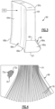
- Figure 2 illustrates a portion of the fan 42.
- Each fan blade 60 includes an airfoil section 64 that spans along a radial direction R between first and second radial ends 64a (outer)/64b (inner), and a dovetail 66 located at the second end 64b of the airfoil section 64.
- the airfoil section 64 connected by a neck 65 to the dovetail 66.
- the neck 65 is a location at which the airfoil section 64 starts to flare to form the dovetail 66.
- the dovetail 66 has a forward face 66a, an aft face 66b, and a dovetail body 66c that extends from the forward face 66a to the aft face 66b.
- the dovetail body has a radially-inwardly facing side 67 that is parallel along its full axial length to the engine axis A.
- the aft face 66b is circumferentially offset from the forward face 66a such that the dovetail body 66c curves from the forward face 66a to the aft face 66b.
- the dovetail body 66c curves continuously from forward face 66a to aft face 66b.
- the dovetail body 66c may be straight instead of curved, in which case the faces 66a/66b will have no circumferential offset.
- a straight design is somewhat compliant (able to roll) due to impact loads, and is generally easier to manufacture and inspect.
- a curved design is more closely aligned with the curvature of the airfoil root and therefore generally creates a smoother transition between the airfoil and the dovetail; however, it is more complex to manufacture and inspect and creates a somewhat less compliant attachment for impact loads (compared to a straight design).
- the fan hub 62 includes a plurality of axial doveslots 68 that extend from the forward face to the aft face of the hub 62.
- the doveslots 68 are also curved and are generally of complementary geometry to the geometry of the dovetails 66 such that the dovetails 66 interlock with the doveslots 68 to radially retain the blades 60 on the hub 62.
- a wear pad, wear coating, or the like may be provided between the dovetail 66 and the sides of the doveslot 68 to reduce wear on the dovetail 66, the doveslot 68, or both.
- the airfoil section 64 and the dovetail 66 are formed of a fiber-reinforced composite material 70 (shown in cutaway).
- the composite material 70 generally includes fiber tows 72a disposed in a matrix 72b.
- the fiber tows 72a are lightweight, high-strength fiber tows, such as but not limited to, carbon fiber tows, aramid fiber tows, or glass fiber tows.
- the matrix 72b is a polymer matrix, such as but not limited to, epoxy.
- the composite material 70 includes inter-section fiber plies 74.
- a "ply” refers to a layer of fiber tows.
- the layer includes a woven fabric, a tape with multiple fiber tows, or multiple fabrics and/or tapes that together make-up a distinct layer.
- the prefix "inter-" means that each ply 74 extends in both the airfoil section 64 and the dovetail 66.
- the plies 74 and the wedges 76 extend the full axial length of the blade 60.
- Engines may occasionally ingest foreign objects.
- the foreign objects can impact airfoils, particularly fan blades at the front of the engine 20.
- Such impacts can induce bending stresses on one or more blades in the fan.
- fan blades that are formed of fiber-reinforced composites that have fiber plies may experience fiber ply delamination along the boundary between plies when subjected to bending stresses from foreign object impacts.
- at the neck where the blade flares to form the dovetail there is a curvature that can act as a stress riser, concentrating induced bending stress in a relatively small region, which may then cause delamination. Extensive delamination and blade damage could in some instances lead to blade detachment.
- the dovetails 66 of the disclosed blades 60 have an asymmetric geometry that is configured to reduce stress concentration from impacts on the blade, thus enhancing blade durability.
- Figure 5 illustrates an axial view of a representative one of the dovetails 66 in the doveslot 68.
- the dovetail 66 is asymmetric about the radial direction R.
- the profile of the cross-section of the dovetail 66 is asymmetric relative to the radial direction, wherein the radial direction at each cross-section bisects the cross-section of the airfoil section 64.
- the dovetail 66 includes first and second circumferential sides 66d/66e that are sloped so as to have a radial component, i.e., the sides 66d/66e face radially outwardly and, at least at times, engage the sides of the doveslot 68 to retain the blade 60 on the hub 62.
- the sides 66d/66e are flat such that contact stresses across the sides can be evenly distributed by interfacial contact with the sides of the doveslot 68.
- the sides 66d/66e each form a different non-zero angle, designated at X1 and X2 in Figure 5 .
- the angles X1 and X2 are taken relative to the radial direction R such that the included angles open radially inwardly.
- One of the non-zero angles, in this example X1 is 10° or less, for example from 5° to 10°.
- the sum of the angles X1 and X2 is from 35° to 45°.
- the angle X1 of 10° or less provides a relatively low stress concentration factor at the neck 65.
- the airfoil section 64 defines a suction side 64c and a pressure side 64d
- the first circumferential side 66d has the angle X1 that is less than 10°
- the first circumferential side 66d is on the pressure side 64d.
- the pressure side 64d is oriented such that, given the rotation of the fan blades 60 about the axis A, the foreign object "FO" will primarily impact the pressure side 64d.
- the impact induces a bending of the blade 60 in which the first circumferential side 66d of the dovetail 66 will be urged forward to press against a side of the doveslot, creating stress at the neck 65 (which is radially outboard of the doveslot 68) on the pressure side 64d.
- the radius of curvature at the neck 65 is relatively large (in comparison to the smaller radius of curvature at the neck on the suction side 64c due to the larger angle X2), which reduces or limits the stress concentration.
- the blade 60 will be more tolerant to foreign object impact that may otherwise result in substantial delamination.
- the sum of the angles X1 and X2 (from 35° to 45°) is thought to represent a useful balance between the shallowness of the angle X1 to reduce stress concentration versus the need to have enough of a radial component to the slopes of the sides 66d/66e to ensure that the blade can remain retained in the doveslot 68 under the centrifugal force on the blade 60 during rotation. Accordingly, the blade 60 is configured to mitigate impact damage by managing the induced bending stresses to avoid high stress concentrations that could otherwise lead to substantial delamination.
Landscapes
- Engineering & Computer Science (AREA)
- Mechanical Engineering (AREA)
- General Engineering & Computer Science (AREA)
- Chemical & Material Sciences (AREA)
- Materials Engineering (AREA)
- Composite Materials (AREA)
- Architecture (AREA)
- Structures Of Non-Positive Displacement Pumps (AREA)
Applications Claiming Priority (1)
| Application Number | Priority Date | Filing Date | Title |
|---|---|---|---|
| US18/541,612 US20250198292A1 (en) | 2023-12-15 | 2023-12-15 | Blade configured for impact tolerance |
Publications (1)
| Publication Number | Publication Date |
|---|---|
| EP4579059A1 true EP4579059A1 (de) | 2025-07-02 |
Family
ID=93924026
Family Applications (1)
| Application Number | Title | Priority Date | Filing Date |
|---|---|---|---|
| EP24219992.5A Pending EP4579059A1 (de) | 2023-12-15 | 2024-12-13 | Für stosstoleranz konfigurierte schaufel |
Country Status (2)
| Country | Link |
|---|---|
| US (1) | US20250198292A1 (de) |
| EP (1) | EP4579059A1 (de) |
Families Citing this family (2)
| Publication number | Priority date | Publication date | Assignee | Title |
|---|---|---|---|---|
| CN120969007A (zh) * | 2025-10-10 | 2025-11-18 | 长江勘测规划设计研究有限责任公司 | 冲击式水轮机、转轮及转轮的装配方法 |
| CN120969009A (zh) * | 2025-10-10 | 2025-11-18 | 长江勘测规划设计研究有限责任公司 | 冲击式水轮机、水斗以及用于水斗与轮毂的榫卯连接结构 |
Citations (5)
| Publication number | Priority date | Publication date | Assignee | Title |
|---|---|---|---|---|
| DE2149655A1 (de) * | 1971-09-17 | 1973-03-22 | Bbc Brown Boveri & Cie | Verfahren zur herstellung einer schaufel fuer stroemungsmaschinen |
| DE4108085A1 (de) * | 1990-03-19 | 1991-09-26 | Gen Electric | Laufschaufel fuer ein gasturbinentriebwerk |
| US8100662B2 (en) * | 2006-10-18 | 2012-01-24 | Rolls-Royce Deutschland Ltd & Co Kg | Fan blade made of a textile composite material |
| US10174624B1 (en) * | 2014-06-05 | 2019-01-08 | United Technologies Corporation | Composite blade root lay-up |
| EP3896253A1 (de) * | 2020-04-13 | 2021-10-20 | Raytheon Technologies Corporation | Schaufel mit integrierter plattform für gasturbinenmotoren |
Family Cites Families (7)
| Publication number | Priority date | Publication date | Assignee | Title |
|---|---|---|---|---|
| US4084922A (en) * | 1976-12-27 | 1978-04-18 | Electric Power Research Institute, Inc. | Turbine rotor with pin mounted ceramic turbine blades |
| FR2608674B1 (fr) * | 1986-12-17 | 1991-04-19 | Snecma | Roue de turbine a aubes ceramique |
| US8573947B2 (en) * | 2010-03-10 | 2013-11-05 | United Technologies Corporation | Composite fan blade dovetail root |
| DE102011077501A1 (de) * | 2011-06-14 | 2012-12-20 | Rolls-Royce Deutschland Ltd & Co Kg | Rotorvorrichtung für ein Strahltriebwerk mit einem Scheibenrad und mehreren Laufschaufeln |
| JP2016035209A (ja) * | 2014-08-01 | 2016-03-17 | 三菱日立パワーシステムズ株式会社 | 軸流圧縮機、及び軸流圧縮機を備えたガスタービン |
| US10655479B2 (en) * | 2018-07-11 | 2020-05-19 | Rolls-Royce Corporation | Turbine wheel assembly with ceramic matrix composite blades |
| US11280202B2 (en) * | 2020-04-06 | 2022-03-22 | Raytheon Technologies Corporation | Balanced composite root region for a blade of a gas turbine engine |
-
2023
- 2023-12-15 US US18/541,612 patent/US20250198292A1/en active Pending
-
2024
- 2024-12-13 EP EP24219992.5A patent/EP4579059A1/de active Pending
Patent Citations (5)
| Publication number | Priority date | Publication date | Assignee | Title |
|---|---|---|---|---|
| DE2149655A1 (de) * | 1971-09-17 | 1973-03-22 | Bbc Brown Boveri & Cie | Verfahren zur herstellung einer schaufel fuer stroemungsmaschinen |
| DE4108085A1 (de) * | 1990-03-19 | 1991-09-26 | Gen Electric | Laufschaufel fuer ein gasturbinentriebwerk |
| US8100662B2 (en) * | 2006-10-18 | 2012-01-24 | Rolls-Royce Deutschland Ltd & Co Kg | Fan blade made of a textile composite material |
| US10174624B1 (en) * | 2014-06-05 | 2019-01-08 | United Technologies Corporation | Composite blade root lay-up |
| EP3896253A1 (de) * | 2020-04-13 | 2021-10-20 | Raytheon Technologies Corporation | Schaufel mit integrierter plattform für gasturbinenmotoren |
Also Published As
| Publication number | Publication date |
|---|---|
| US20250198292A1 (en) | 2025-06-19 |
Similar Documents
| Publication | Publication Date | Title |
|---|---|---|
| US11047245B2 (en) | CMC component attachment pin | |
| US11215064B2 (en) | Compact pin attachment for CMC components | |
| US11248480B2 (en) | Intersegment seal for CMC boas assembly | |
| US11466577B2 (en) | CMC vane mate face flange | |
| US11591920B2 (en) | Vane arc segment with curved radial flange | |
| EP4579059A1 (de) | Für stosstoleranz konfigurierte schaufel | |
| US9482111B2 (en) | Fan containment case with thermally conforming liner | |
| US11078793B2 (en) | Gas turbine engine airfoil with large thickness properties | |
| US11215054B2 (en) | Airfoil with encapsulating sheath | |
| US11466576B2 (en) | Airfoil with continuous stiffness joint | |
| US20200362717A1 (en) | Cmc boas arrangement | |
| EP3825518B1 (de) | Leitschaufelrückhalteeinrichtung | |
| US11073030B1 (en) | Airfoil attachment for gas turbine engines | |
| US20190106989A1 (en) | Gas turbine engine airfoil | |
| US11655758B1 (en) | CMC vane mate face flanges with through-ply seal slots | |
| EP3865669B1 (de) | Schaufelbogenabschnittplattformflansch eines gasturbinentriebwerks mit kappe | |
| US10753368B2 (en) | Multi-piece non-linear airfoil | |
| US11725519B2 (en) | Platform for an airfoil of a gas turbine engine | |
| US11098608B2 (en) | CMC BOAS with internal support structure | |
| EP4538502A1 (de) | Schaufel aus verbundwerkstoff mit verjüngtem schaufelfuss |
Legal Events
| Date | Code | Title | Description |
|---|---|---|---|
| PUAI | Public reference made under article 153(3) epc to a published international application that has entered the european phase |
Free format text: ORIGINAL CODE: 0009012 |
|
| STAA | Information on the status of an ep patent application or granted ep patent |
Free format text: STATUS: THE APPLICATION HAS BEEN PUBLISHED |
|
| AK | Designated contracting states |
Kind code of ref document: A1 Designated state(s): AL AT BE BG CH CY CZ DE DK EE ES FI FR GB GR HR HU IE IS IT LI LT LU LV MC ME MK MT NL NO PL PT RO RS SE SI SK SM TR |
|
| STAA | Information on the status of an ep patent application or granted ep patent |
Free format text: STATUS: REQUEST FOR EXAMINATION WAS MADE |
|
| 17P | Request for examination filed |
Effective date: 20251230 |