EP4579062A1 - Turbinenmotor mit einer düse mit kühlmerkmalen - Google Patents
Turbinenmotor mit einer düse mit kühlmerkmalen Download PDFInfo
- Publication number
- EP4579062A1 EP4579062A1 EP24216318.6A EP24216318A EP4579062A1 EP 4579062 A1 EP4579062 A1 EP 4579062A1 EP 24216318 A EP24216318 A EP 24216318A EP 4579062 A1 EP4579062 A1 EP 4579062A1
- Authority
- EP
- European Patent Office
- Prior art keywords
- turbine
- nozzle
- engine
- slots
- slot
- Prior art date
- Legal status (The legal status is an assumption and is not a legal conclusion. Google has not performed a legal analysis and makes no representation as to the accuracy of the status listed.)
- Pending
Links
Images


Classifications
-
- F—MECHANICAL ENGINEERING; LIGHTING; HEATING; WEAPONS; BLASTING
- F01—MACHINES OR ENGINES IN GENERAL; ENGINE PLANTS IN GENERAL; STEAM ENGINES
- F01D—NON-POSITIVE DISPLACEMENT MACHINES OR ENGINES, e.g. STEAM TURBINES
- F01D5/00—Blades; Blade-carrying members; Heating, heat-insulating, cooling or antivibration means on the blades or the members
- F01D5/12—Blades
- F01D5/14—Form or construction
- F01D5/18—Hollow blades, i.e. blades with cooling or heating channels or cavities; Heating, heat-insulating or cooling means on blades
- F01D5/187—Convection cooling
- F01D5/188—Convection cooling with an insert in the blade cavity to guide the cooling fluid, e.g. forming a separation wall
- F01D5/189—Convection cooling with an insert in the blade cavity to guide the cooling fluid, e.g. forming a separation wall the insert having a tubular cross-section, e.g. airfoil shape
-
- F—MECHANICAL ENGINEERING; LIGHTING; HEATING; WEAPONS; BLASTING
- F01—MACHINES OR ENGINES IN GENERAL; ENGINE PLANTS IN GENERAL; STEAM ENGINES
- F01D—NON-POSITIVE DISPLACEMENT MACHINES OR ENGINES, e.g. STEAM TURBINES
- F01D5/00—Blades; Blade-carrying members; Heating, heat-insulating, cooling or antivibration means on the blades or the members
- F01D5/12—Blades
- F01D5/14—Form or construction
- F01D5/18—Hollow blades, i.e. blades with cooling or heating channels or cavities; Heating, heat-insulating or cooling means on blades
-
- F—MECHANICAL ENGINEERING; LIGHTING; HEATING; WEAPONS; BLASTING
- F01—MACHINES OR ENGINES IN GENERAL; ENGINE PLANTS IN GENERAL; STEAM ENGINES
- F01D—NON-POSITIVE DISPLACEMENT MACHINES OR ENGINES, e.g. STEAM TURBINES
- F01D5/00—Blades; Blade-carrying members; Heating, heat-insulating, cooling or antivibration means on the blades or the members
- F01D5/12—Blades
- F01D5/14—Form or construction
- F01D5/141—Shape, i.e. outer, aerodynamic form
- F01D5/142—Shape, i.e. outer, aerodynamic form of the blades of successive rotor or stator blade-rows
- F01D5/143—Contour of the outer or inner working fluid flow path wall, i.e. shroud or hub contour
-
- F—MECHANICAL ENGINEERING; LIGHTING; HEATING; WEAPONS; BLASTING
- F01—MACHINES OR ENGINES IN GENERAL; ENGINE PLANTS IN GENERAL; STEAM ENGINES
- F01D—NON-POSITIVE DISPLACEMENT MACHINES OR ENGINES, e.g. STEAM TURBINES
- F01D9/00—Stators
- F01D9/02—Nozzles; Nozzle boxes; Stator blades; Guide conduits, e.g. individual nozzles
- F01D9/04—Nozzles; Nozzle boxes; Stator blades; Guide conduits, e.g. individual nozzles forming ring or sector
- F01D9/041—Nozzles; Nozzle boxes; Stator blades; Guide conduits, e.g. individual nozzles forming ring or sector using blades
-
- F—MECHANICAL ENGINEERING; LIGHTING; HEATING; WEAPONS; BLASTING
- F01—MACHINES OR ENGINES IN GENERAL; ENGINE PLANTS IN GENERAL; STEAM ENGINES
- F01D—NON-POSITIVE DISPLACEMENT MACHINES OR ENGINES, e.g. STEAM TURBINES
- F01D25/00—Component parts, details, or accessories, not provided for in, or of interest apart from, other groups
- F01D25/08—Cooling; Heating; Heat-insulation
- F01D25/12—Cooling
-
- F—MECHANICAL ENGINEERING; LIGHTING; HEATING; WEAPONS; BLASTING
- F01—MACHINES OR ENGINES IN GENERAL; ENGINE PLANTS IN GENERAL; STEAM ENGINES
- F01D—NON-POSITIVE DISPLACEMENT MACHINES OR ENGINES, e.g. STEAM TURBINES
- F01D9/00—Stators
- F01D9/02—Nozzles; Nozzle boxes; Stator blades; Guide conduits, e.g. individual nozzles
-
- F—MECHANICAL ENGINEERING; LIGHTING; HEATING; WEAPONS; BLASTING
- F02—COMBUSTION ENGINES; HOT-GAS OR COMBUSTION-PRODUCT ENGINE PLANTS
- F02C—GAS-TURBINE PLANTS; AIR INTAKES FOR JET-PROPULSION PLANTS; CONTROLLING FUEL SUPPLY IN AIR-BREATHING JET-PROPULSION PLANTS
- F02C7/00—Features, components parts, details or accessories, not provided for in, or of interest apart form groups F02C1/00 - F02C6/00; Air intakes for jet-propulsion plants
- F02C7/12—Cooling of plants
- F02C7/16—Cooling of plants characterised by cooling medium
- F02C7/18—Cooling of plants characterised by cooling medium the medium being gaseous, e.g. air
-
- F—MECHANICAL ENGINEERING; LIGHTING; HEATING; WEAPONS; BLASTING
- F05—INDEXING SCHEMES RELATING TO ENGINES OR PUMPS IN VARIOUS SUBCLASSES OF CLASSES F01-F04
- F05D—INDEXING SCHEME FOR ASPECTS RELATING TO NON-POSITIVE-DISPLACEMENT MACHINES OR ENGINES, GAS-TURBINES OR JET-PROPULSION PLANTS
- F05D2240/00—Components
- F05D2240/10—Stators
- F05D2240/12—Fluid guiding means, e.g. vanes
- F05D2240/122—Fluid guiding means, e.g. vanes related to the trailing edge of a stator vane
-
- F—MECHANICAL ENGINEERING; LIGHTING; HEATING; WEAPONS; BLASTING
- F05—INDEXING SCHEMES RELATING TO ENGINES OR PUMPS IN VARIOUS SUBCLASSES OF CLASSES F01-F04
- F05D—INDEXING SCHEME FOR ASPECTS RELATING TO NON-POSITIVE-DISPLACEMENT MACHINES OR ENGINES, GAS-TURBINES OR JET-PROPULSION PLANTS
- F05D2250/00—Geometry
- F05D2250/10—Two-dimensional
- F05D2250/12—Two-dimensional rectangular
-
- F—MECHANICAL ENGINEERING; LIGHTING; HEATING; WEAPONS; BLASTING
- F05—INDEXING SCHEMES RELATING TO ENGINES OR PUMPS IN VARIOUS SUBCLASSES OF CLASSES F01-F04
- F05D—INDEXING SCHEME FOR ASPECTS RELATING TO NON-POSITIVE-DISPLACEMENT MACHINES OR ENGINES, GAS-TURBINES OR JET-PROPULSION PLANTS
- F05D2250/00—Geometry
- F05D2250/10—Two-dimensional
- F05D2250/14—Two-dimensional elliptical
- F05D2250/141—Two-dimensional elliptical circular
-
- F—MECHANICAL ENGINEERING; LIGHTING; HEATING; WEAPONS; BLASTING
- F05—INDEXING SCHEMES RELATING TO ENGINES OR PUMPS IN VARIOUS SUBCLASSES OF CLASSES F01-F04
- F05D—INDEXING SCHEME FOR ASPECTS RELATING TO NON-POSITIVE-DISPLACEMENT MACHINES OR ENGINES, GAS-TURBINES OR JET-PROPULSION PLANTS
- F05D2260/00—Function
- F05D2260/20—Heat transfer, e.g. cooling
- F05D2260/202—Heat transfer, e.g. cooling by film cooling
Definitions
- exhaust gas temperature refers to a gas temperature in a turbine engine.
- EGT is a "redline exhaust gas temperature,” which refers to a maximum permitted takeoff temperature documented in a Federal Aviation Administration ("FAA”)-type certificate data sheet.
- FAA Federal Aviation Administration
- redline exhaust gas temperature EGT refers to a maximum permitted takeoff that the engine is rated to withstand.
- EGT is a temperature of an airflow measured downstream of a first stage stator of an HP turbine of an engine. In embodiments wherein the engine is configured as a three-spool engine, EGT is measured downstream of the last stage of rotor blades of an intermediate speed turbine.
- redline exhaust temperature EGT is sometimes also referred to as an indicated turbine exhaust gas temperature or indicated turbine temperature.
- total cooling hole area refers to the sum of flow areas of cooling holes formed in a baffle insert.
- the blades and vanes are circumferentially arranged about an engine centerline.
- the blades are mounted to a rotating structure, such as a disk, to effect rotation about the engine centerline.
- the vanes are stationary and mounted to a casing that surrounds the blades.
- the vanes are mounted to a rotating drum that surrounds the blades and rotates about the engine centerline.
- a “nozzle set” is an annular ring of vanes arranged axially adjacent a set of blades to direct the flow of combustion gases through the turbine engine.
- a “nozzle segment” refers to at least two circumferentially-adjacent vanes of the annular nozzle set. As illustrated, a nozzle segment may include two individual vanes - a leading vane and a trailing vane. Individual nozzle segments are combined to form the annular nozzle.
- connection references e.g., attached, coupled, connected, and joined are to be construed broadly and can include intermediate structural elements between a collection of elements and relative movement between elements unless otherwise indicated. As such, connection references do not necessarily infer those two elements are directly connected and in fixed relation to one another.
- the exemplary drawings are for purposes of illustration only. The dimensions, positions, order, and relative sizes of elements reflected in the drawings attached hereto can vary.
- turbine nozzles that limit stresses in each vane of a nozzle segment.
- the trailing vane may exhibit significantly higher stresses that limit the life of the turbine nozzle.
- Nozzle assemblies are typically evaluated according to a size, type, etc. that satisfies three key requirements: sizing to existing engine systems, acceptable stress levels, and acceptable stress load paths. This is a labor and time intensive process because the process is iterative and involves the selection of particular dimensions designed for operating within current engine systems, determining the stresses associated with particular iterations, and evaluating whether these stresses are limited during operating cycles.
- the inventors have sought to improve upon current nozzle assembly design to reduce the aforementioned stresses and improve engine performance.
- cooling features in certain locations of the vanes of a turbine nozzle limit local stresses in the vanes for certain engine systems. These locations include a trailing edge of an airfoil of a vane and an insert or baffle disposed within the airfoil of the vane.
- cooling geometries e.g., in the form of trailing edge slots or holes
- improvements to the trailing edge are provided through the inclusion of more robust trailing edge cooling geometries, and improvements to the airfoil vane panels are provided through the inclusion of updated backside cooling.
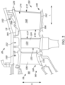
- FIG. 1 provides a schematic cross-sectional view of a turbine engine 10, which may be a gas turbine engine, in accordance with an exemplary embodiment of the present disclosure.
- the turbine engine 10 defines an axial direction A (extending parallel to a longitudinal or axial centerline 12 provided for reference) and a radial direction R.
- a circumferential direction C extends three hundred sixty degrees (360°) around the axial centerline 12.
- the turbine engine 10 includes a fan section 14 and a core turbine engine or engine core 16 disposed downstream of the fan section 14.
- the exemplary engine core 16 depicted generally includes a substantially tubular outer casing 18 that defines an annular core inlet 20.
- the outer casing 18 encases, in serial flow relationship, a compressor section including a booster or low pressure (LP) compressor 22 and a high pressure (HP) compressor 24; a combustion section 26; a turbine section including a high pressure (HP) turbine 28 and a low pressure (LP) turbine 30; and an exhaust nozzle section 32.
- a high pressure (HP) shaft or spool 34 drivingly connects the HP turbine 28 to the HP compressor 24.
- a low pressure (LP) shaft or spool 36 drivingly connects the LP turbine 30 to the LP compressor 22.
- additional spools may be provided.
- the fan section 14 includes a fan 38 having a plurality of fan blades 40 coupled to a disk 42 in a spaced apart manner. As depicted, fan blades 40 extend outward from disk 42 generally along the radial direction R. The fan blades 40 and disk 42 are together rotatable about the longitudinal axis 12 by the LP shaft 36. In some embodiments, a power gear box having a plurality of gears can be included for stepping down the rotational speed of the LP shaft 36 to a more efficient rotational fan speed.
- disk 42 is covered by rotatable spinner 48.
- the rotatable spinner 48 is aerodynamically contoured to promote an airflow through the plurality of fan blades 40.
- the exemplary fan section 14 includes an annular fan casing or outer nacelle 50 that circumferentially surrounds the fan 38 and/or at least a portion of the engine core 16.
- the nacelle 50 is supported relative to the engine core 16 by a plurality of circumferentially-spaced outlet guide vanes 52.
- a downstream section 54 of the nacelle 50 can extend over an outer portion of the engine core 16 so as to define a bypass airflow passage 56 therebetween as shown in FIG. 1 .
- a volume of air 58 enters turbine engine 10 through an associated inlet 60 of the nacelle 50 and/or fan section 14.
- a first portion of the air 58 (as indicated by arrows 62) is directed or routed into the bypass airflow passage 56 and a second portion of the air 58 (as indicated by arrows 64) is directed or routed into the LP compressor 22.
- the ratio between the first portion of air 62 and the second portion of air 64 is commonly known as a bypass ratio.
- the pressure of the second portion of air 64 is increased as it is routed through the high pressure (HP) compressor 24 and into the combustion section 26, where it is mixed with fuel and burned to provide combustion gases 66.
- HP high pressure
- the combustion gases 66 are routed through the HP turbine 28.
- a portion of thermal and/or kinetic energy from the combustion gases 66 is extracted via passage through sequential stages of HP turbine stator vanes 68 and HP turbine rotor blades 70 that are coupled to the HP shaft or spool 34.
- the energy that is extracted causes the HP shaft or spool 34 to rotate and supports operation of the HP compressor 24.
- the combustion gases 66 are then routed through the LP turbine 30.
- a second portion of thermal and kinetic energy is extracted from the combustion gases 66 via passage through sequential stages of LP turbine stator vanes 72 and LP turbine rotor blades 74 that are coupled to the LP shaft or spool 36.
- the energy that is extracted causes the LP shaft or spool 36 to rotate and supports operation of the LP compressor 22 and/or rotation of the fan 38.
- the combustion gases 66 are subsequently routed through the exhaust nozzle section 32 of the engine core 16 to provide propulsive thrust.
- the HP turbine 28, the LP turbine 30, and the exhaust nozzle section 32 at least partially define a hot gas path 78 for routing the combustion gases 66 through the engine core 16.
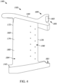
- the trailing edge 172 may be a blunt edge having an arcuate or generally planar wall or surface 202 that extends between the pressure side 180 and the suction side 182 of the vane airfoil 160.
- the edge can be cast, machined, or polished depending upon the desired result.
- the shape could be rounded, elliptical, blunt, or the like.
- the vane airfoil 160 includes cooling features 190 in the form of apertures in the trailing edge 172.
- the cooling features 190 may be formed with the vane airfoil 160 (e.g., cast), or may be subsequently formed (e.g., machined) in the trailing edge surface 202 after construction of the vane airfoil 160.
- the sum of the flow areas of the cooling features 190 defines a total slot flow area (SFA) formed in the trailing edge surface 202.
- SFA total slot flow area
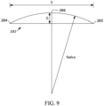
- the total cooling hole area (CHA) is defined as A m being equal to M* ⁇ *r 2 , where "M” is equal to the total number of commonly-dimensioned cooling holes 240 formed in the baffle insert 220, and "r” is a radius of each of the cooling holes 240.
- Expression (3) contemplates non-commonly-dimensioned cooling holes 240, as well as geometries other than or in addition to circles.
- Reliability includes performing as intended in harsh environments and over a wide range of environmental conditions. Numerous studies were used to evaluate effects on the combined influences of aero performance, thermal, and mechanical strain on a vane. These studies include both analytical and engine testing of vane designs to evaluate the thermal stress profiles of the proposed design. For instance, inventive designs exhibit a more uniform, i.e., less pronounced, thermal gradient in operation. Accordingly, the inventors found that thermal stresses on the various components for the inventive designs fell within acceptable ranges that result in improved overall durability whereas other designs regarding the applicable air flow failed to meet these acceptable ranges.
- the designs include various geometries of cooling features 190 in the trailing edge 172 of a vane airfoil 160 in combination with various geometries of the cooling holes 240 of a baffle insert 220.
- the examples in TABLE 1 (presented below) produce an improved engine that mitigates or reduces local stresses at the corresponding operating conditions.
- TABLE 3 Example SFA (m ⁇ 2) CHA (m ⁇ 2) EGT (deg C) Core Speed (Hz) E (dimensionless) 1 0.0000305 0.0000720 1010 182 -0.203 2 0.0000430 0.0000881 999 173 -0.129 3 0.0000297 0.0000809 1047 166 -0.133 4 0.0000457 0.0000790 1170 200 -0.299
- a method of assembly comprising: mounting a plurality of vanes to a turbine engine, the turbine engine including:
- a turbine engine comprising:
- slots include a first slot having a first geometry and a second slot having a second geometry different than the first slot.
- slots include at least one slot having a circular geometry.
- slots include at least one slot having a rectangular geometry.
- the slots include a first slot having a first geometry and a second slot having a second geometry different than the first slot.
- the slots include at least one slot having a rectangular geometry.
Landscapes
- Engineering & Computer Science (AREA)
- Mechanical Engineering (AREA)
- General Engineering & Computer Science (AREA)
- Physics & Mathematics (AREA)
- Fluid Mechanics (AREA)
- Turbine Rotor Nozzle Sealing (AREA)
- Chemical & Material Sciences (AREA)
- Combustion & Propulsion (AREA)
Applications Claiming Priority (2)
| Application Number | Priority Date | Filing Date | Title |
|---|---|---|---|
| US202363605164P | 2023-12-01 | 2023-12-01 | |
| US202363605323P | 2023-12-01 | 2023-12-01 |
Publications (1)
| Publication Number | Publication Date |
|---|---|
| EP4579062A1 true EP4579062A1 (de) | 2025-07-02 |
Family
ID=93742678
Family Applications (2)
| Application Number | Title | Priority Date | Filing Date |
|---|---|---|---|
| EP24216317.8A Pending EP4571050A1 (de) | 2023-12-01 | 2024-11-28 | Turbinenmotor mit einer düse mit kühlmerkmalen |
| EP24216318.6A Pending EP4579062A1 (de) | 2023-12-01 | 2024-11-28 | Turbinenmotor mit einer düse mit kühlmerkmalen |
Family Applications Before (1)
| Application Number | Title | Priority Date | Filing Date |
|---|---|---|---|
| EP24216317.8A Pending EP4571050A1 (de) | 2023-12-01 | 2024-11-28 | Turbinenmotor mit einer düse mit kühlmerkmalen |
Country Status (2)
| Country | Link |
|---|---|
| US (2) | US12467366B2 (de) |
| EP (2) | EP4571050A1 (de) |
Citations (3)
| Publication number | Priority date | Publication date | Assignee | Title |
|---|---|---|---|---|
| EP1039096A2 (de) * | 1999-03-22 | 2000-09-27 | General Electric Company | Turbinenleitapparat |
| US7775769B1 (en) * | 2007-05-24 | 2010-08-17 | Florida Turbine Technologies, Inc. | Turbine airfoil fillet region cooling |
| US20180135426A1 (en) * | 2016-11-15 | 2018-05-17 | Rolls-Royce Corporation | Dual-wall airfoil with leading edge cooling slot |
Family Cites Families (58)
| Publication number | Priority date | Publication date | Assignee | Title |
|---|---|---|---|---|
| DE3023466C2 (de) * | 1980-06-24 | 1982-11-25 | MTU Motoren- und Turbinen-Union München GmbH, 8000 München | Einrichtung zur Verminderung von Sekundärströmungsverlusten in einem beschaufelten Strömungskanal |
| US6095755A (en) | 1996-11-26 | 2000-08-01 | United Technologies Corporation | Gas turbine engine airfoils having increased fatigue strength |
| US6077036A (en) * | 1998-08-20 | 2000-06-20 | General Electric Company | Bowed nozzle vane with selective TBC |
| US6382906B1 (en) * | 2000-06-16 | 2002-05-07 | General Electric Company | Floating spoolie cup impingement baffle |
| US6681558B2 (en) * | 2001-03-26 | 2004-01-27 | General Electric Company | Method of increasing engine temperature limit margins |
| US6932568B2 (en) * | 2003-02-27 | 2005-08-23 | General Electric Company | Turbine nozzle segment cantilevered mount |
| US7008185B2 (en) * | 2003-02-27 | 2006-03-07 | General Electric Company | Gas turbine engine turbine nozzle bifurcated impingement baffle |
| US8876989B2 (en) | 2007-08-31 | 2014-11-04 | General Electric Company | Low rhenium nickel base superalloy compositions and superalloy articles |
| FR2926322B1 (fr) | 2008-01-10 | 2012-08-03 | Snecma | Aube bi-pale avec lames. |
| US8177488B2 (en) * | 2008-11-29 | 2012-05-15 | General Electric Company | Integrated service tube and impingement baffle for a gas turbine engine |
| US8408872B2 (en) | 2009-09-24 | 2013-04-02 | General Electric Company | Fastback turbulator structure and turbine nozzle incorporating same |
| US20110116912A1 (en) | 2009-11-13 | 2011-05-19 | Mccall Thomas | Zoned discontinuous coating for high pressure turbine component |
| US8684684B2 (en) | 2010-08-31 | 2014-04-01 | General Electric Company | Turbine assembly with end-wall-contoured airfoils and preferenttial clocking |
| US9506351B2 (en) | 2012-04-27 | 2016-11-29 | General Electric Company | Durable turbine vane |
| US20140341723A1 (en) * | 2013-03-15 | 2014-11-20 | General Electric Company | Gas turbine vane insert to control particulate deposition |
| US20160290645A1 (en) * | 2013-11-21 | 2016-10-06 | United Technologies Corporation | Axisymmetric offset of three-dimensional contoured endwalls |
| US9957816B2 (en) | 2014-05-29 | 2018-05-01 | General Electric Company | Angled impingement insert |
| WO2016025054A2 (en) * | 2014-05-29 | 2016-02-18 | General Electric Company | Engine components with cooling features |
| WO2015183899A1 (en) * | 2014-05-29 | 2015-12-03 | General Electric Company | Angled impingement insert with discrete cooling features |
| EP2960439A1 (de) * | 2014-06-26 | 2015-12-30 | Siemens Aktiengesellschaft | Turbomaschine mit äußerer Dichtung und Verwendung dieser Turbomaschine |
| US10240462B2 (en) * | 2016-01-29 | 2019-03-26 | General Electric Company | End wall contour for an axial flow turbine stage |
| US10450897B2 (en) | 2016-07-18 | 2019-10-22 | General Electric Company | Shroud for a gas turbine engine |
| US9997047B2 (en) * | 2016-10-03 | 2018-06-12 | General Electric Company | System and method for detecting lubricated bearing condition |
| US20180111200A1 (en) | 2016-10-20 | 2018-04-26 | General Electric Company | Porous film hole exit and method for making same |
| IT201700008681A1 (it) | 2017-01-26 | 2018-07-26 | Nuovo Pignone Tecnologie Srl | Sistema di turbina a gas |
| US20180347442A1 (en) | 2017-05-31 | 2018-12-06 | General Electric Company | Lattice structure in cooling pathway by additive manufacture |
| GB201813083D0 (en) * | 2018-08-10 | 2018-09-26 | Rolls Royce Plc | Efficient gas turbine engine |
| US11220916B2 (en) * | 2020-01-22 | 2022-01-11 | General Electric Company | Turbine rotor blade with platform with non-linear cooling passages by additive manufacture |
| US11268394B2 (en) | 2020-03-13 | 2022-03-08 | General Electric Company | Nozzle assembly with alternating inserted vanes for a turbine engine |
| KR102621756B1 (ko) | 2020-11-27 | 2024-01-09 | 연세대학교 산학협력단 | 격자구조의 냉각방식을 갖는 가스터빈 베인 및 블레이드 |
| JP6963701B1 (ja) * | 2021-02-01 | 2021-11-10 | 三菱パワー株式会社 | ガスタービン静翼およびガスタービン |
| FR3127024B1 (fr) | 2021-09-10 | 2024-03-08 | Safran Aircraft Engines | Souplesses dans une turbomachine à réducteur |
| FR3127025B1 (fr) | 2021-09-10 | 2024-03-08 | Safran Aircraft Engines | Souplesses dans une turbomachine à réducteur |
| FR3127269B1 (fr) | 2021-09-17 | 2023-09-08 | Safran Aircraft Engines | Turbomachine d’aeronef a helice desaxee |
| FR3129432B1 (fr) | 2021-11-19 | 2023-11-24 | Safran Aircraft Engines | Module de montage d’une aube de soufflante de turbomachine |
| FR3129428B1 (fr) | 2021-11-19 | 2024-09-20 | Safran Aircraft Engines | Ensemble a calage variable pour soufflante de turbomachine |
| FR3129436A1 (fr) | 2021-11-25 | 2023-05-26 | Safran Aircraft Engines | Dispositif de pressurisation d’une enceinte de turbomachine a passage par accouplement curvic ® et turbomachine correspondante. |
| FR3129375B1 (fr) | 2021-11-25 | 2026-01-30 | Safran | Système de conversion et de transport d'énergie électrique pour l'hybridation interne d'une turbomachine d'aéronef |
| FR3129690B1 (fr) | 2021-11-30 | 2025-12-26 | Safran Aircraft Engines | Turbomachine comprenant une enceinte de lubrification et un reducteur de vitesse |
| FR3129970B1 (fr) | 2021-12-02 | 2025-02-14 | Safran Aircraft Engines | Turbomachine comprenant une machine électrique en aval d’un arbre de turbine et entraînée par cet arbre |
| FR3129972B1 (fr) | 2021-12-07 | 2024-12-13 | Safran Aircraft Engines | Boîtier de distribution d’air de refroidissement |
| FR3130323B1 (fr) | 2021-12-13 | 2024-08-23 | Safran Aircraft Engines | Turbomachine pour aeronef comprenant une machine electrique |
| FR3130313B1 (fr) | 2021-12-15 | 2025-02-28 | Safran Aircraft Engines | Procédé de gestion du couple d’une turbomachine |
| FR3130897B1 (fr) | 2021-12-17 | 2023-11-24 | Safran Aircraft Engines | Turbomachine d’aéronef |
| FR3130896B1 (fr) | 2021-12-17 | 2023-12-15 | Safran Aircraft Engines | Turbomachine d’aéronef |
| FR3130894B1 (fr) | 2021-12-20 | 2024-09-06 | Safran Aircraft Engines | Module de turbomachine equipe d’aubes a calage variable et d’une virole annulaire d’interface |
| FR3130875B1 (fr) | 2021-12-20 | 2024-08-09 | Safran Aircraft Engines | Module de turbomachine equipe d’aubes a calage variable et d’un dispostif de transfert d’huile |
| FR3130895B1 (fr) | 2021-12-20 | 2023-11-03 | Safran Aircraft Engines | Module de turbomachine equipe d’un systeme de changement de pas et d’un dispostif de transfert de fluide |
| FR3130874B1 (fr) | 2021-12-20 | 2023-11-10 | Safran Aircraft Engines | Module de turbomachine equipe d’un systeme de changement de pas et d’un dispostif de transfert de fluide a emmanchement en aveugle |
| FR3130877B1 (fr) | 2021-12-20 | 2024-10-25 | Safran Aircraft Engines | Dispostif de transfert de fluide avec moyens de connexion hydraulique et mecanique |
| FR3130879B1 (fr) | 2021-12-22 | 2024-11-08 | Safran Aircraft Engines | Sous-ensemble de turbomachine comportant un col de cygne a configuration amelioree et turbomachine comportant un tel sous-ensemble |
| FR3130747B1 (fr) | 2021-12-22 | 2026-03-06 | Safran Aircraft Engines | Turbomachine d’aeronef comprenant un pilotage de calage de pales par mesures locales de pression |
| FR3132279B1 (fr) | 2022-02-01 | 2024-01-12 | Safran Aircraft Engines | Procédé de freinage d’une turbomachine d’aéronef |
| FR3132743B1 (fr) | 2022-02-14 | 2024-03-08 | Safran Aircraft Engines | Ensemble de turbomachine comprenant un carter |
| FR3132729B1 (fr) | 2022-02-14 | 2025-05-02 | Safran | Ensemble propulsif pour aéronef comprenant une turbomachine à gaz et une machine électrique avec un système de refroidissement comprenant un organe de couplage principal et procédé d’utilisation associé |
| GB2616062B (en) * | 2022-02-28 | 2024-07-17 | Airbus Operations Ltd | Aircraft engine for nitrogen oxide reduction |
| FR3133368B1 (fr) | 2022-03-11 | 2024-08-02 | Safran Aircraft Engines | Ensemble propulsif pour un aeronef |
| FR3133367B1 (fr) | 2022-03-11 | 2024-08-23 | Safran Aircraft Engines | Propulseur aeronautique |
-
2024
- 2024-11-27 US US18/962,252 patent/US12467366B2/en active Active
- 2024-11-27 US US18/961,846 patent/US20260098478A1/en active Pending
- 2024-11-28 EP EP24216317.8A patent/EP4571050A1/de active Pending
- 2024-11-28 EP EP24216318.6A patent/EP4579062A1/de active Pending
Patent Citations (3)
| Publication number | Priority date | Publication date | Assignee | Title |
|---|---|---|---|---|
| EP1039096A2 (de) * | 1999-03-22 | 2000-09-27 | General Electric Company | Turbinenleitapparat |
| US7775769B1 (en) * | 2007-05-24 | 2010-08-17 | Florida Turbine Technologies, Inc. | Turbine airfoil fillet region cooling |
| US20180135426A1 (en) * | 2016-11-15 | 2018-05-17 | Rolls-Royce Corporation | Dual-wall airfoil with leading edge cooling slot |
Also Published As
| Publication number | Publication date |
|---|---|
| EP4571050A1 (de) | 2025-06-18 |
| US12467366B2 (en) | 2025-11-11 |
| US20250179922A1 (en) | 2025-06-05 |
| US20260098478A1 (en) | 2026-04-09 |
Similar Documents
| Publication | Publication Date | Title |
|---|---|---|
| CN108930594B (zh) | 交叉涡轮发动机的空气轴承和热管理喷嘴布置 | |
| CN110300838B (zh) | 用于外径安装型涡轮叶片的热结构 | |
| EP3150803B1 (de) | Schaufelprofil und kühlverfahren | |
| WO2013074165A2 (en) | Asymmetric radial spline seal for a gas turbine engine | |
| EP2264283A2 (de) | Gekühlte Komponente für einen Gasturbinenmotor | |
| EP3456916A1 (de) | Drehbarer drehmomentrahmen für gasturbinenmotoren | |
| EP3141698A1 (de) | Anordnung für eine gasturbine | |
| EP2519721B1 (de) | Dämpferdichtung | |
| EP2855898B1 (de) | Statorschaufel-stossfängerring | |
| EP2623719B1 (de) | Entspannungsschlitze für Turbinenschaufelring | |
| EP3693541B1 (de) | Gasturbinenrotorscheibe mit bogenförmigem schutzmerkmal | |
| US20230037224A1 (en) | Turbine circumferential dovetail leakage reduction | |
| EP4545770A1 (de) | Turbinenmotor und turbinendüse | |
| EP4579062A1 (de) | Turbinenmotor mit einer düse mit kühlmerkmalen | |
| US20240280028A1 (en) | Turbine engine with a blade assembly having a dovetail | |
| US20230243268A1 (en) | Airfoils for gas turbine engines | |
| JP2010084766A (ja) | ガスタービンエンジン用タービンノズル | |
| US11156110B1 (en) | Rotor assembly for a turbine section of a gas turbine engine | |
| US20240369072A1 (en) | Forward load reduction structures for high pressure compressors | |
| US12378889B2 (en) | Turbine engine with a blade assembly having cooling conduits | |
| EP4553279A1 (de) | Turbinenmotor mit einer schaufelanordnung mit kühlleitungen | |
| US20250305447A1 (en) | Compact core arrangement for high bypass ratio gas turbine engine architecture | |
| US11674400B2 (en) | Gas turbine engine nozzles | |
| EP4553274A1 (de) | Turbinenmotor mit einer schaufelanordnung mit einem plattformplenum | |
| US20250283418A1 (en) | Turbine engine with a blade assembly having a set of cooling conduits |
Legal Events
| Date | Code | Title | Description |
|---|---|---|---|
| PUAI | Public reference made under article 153(3) epc to a published international application that has entered the european phase |
Free format text: ORIGINAL CODE: 0009012 |
|
| STAA | Information on the status of an ep patent application or granted ep patent |
Free format text: STATUS: THE APPLICATION HAS BEEN PUBLISHED |
|
| AK | Designated contracting states |
Kind code of ref document: A1 Designated state(s): AL AT BE BG CH CY CZ DE DK EE ES FI FR GB GR HR HU IE IS IT LI LT LU LV MC ME MK MT NL NO PL PT RO RS SE SI SK SM TR |
|
| STAA | Information on the status of an ep patent application or granted ep patent |
Free format text: STATUS: REQUEST FOR EXAMINATION WAS MADE |
|
| 17P | Request for examination filed |
Effective date: 20251217 |