EP4579067A2 - Abgasbehandlungssystem mit vorgeschaltetem scr-katalysator - Google Patents
Abgasbehandlungssystem mit vorgeschaltetem scr-katalysator Download PDFInfo
- Publication number
- EP4579067A2 EP4579067A2 EP25171325.1A EP25171325A EP4579067A2 EP 4579067 A2 EP4579067 A2 EP 4579067A2 EP 25171325 A EP25171325 A EP 25171325A EP 4579067 A2 EP4579067 A2 EP 4579067A2
- Authority
- EP
- European Patent Office
- Prior art keywords
- scr
- catalyst
- amox
- doc
- csf
- Prior art date
- Legal status (The legal status is an assumption and is not a legal conclusion. Google has not performed a legal analysis and makes no representation as to the accuracy of the status listed.)
- Pending
Links
Images











Classifications
-
- B—PERFORMING OPERATIONS; TRANSPORTING
- B01—PHYSICAL OR CHEMICAL PROCESSES OR APPARATUS IN GENERAL
- B01J—CHEMICAL OR PHYSICAL PROCESSES, e.g. CATALYSIS OR COLLOID CHEMISTRY; THEIR RELEVANT APPARATUS
- B01J23/00—Catalysts comprising metals or metal oxides or hydroxides, not provided for in group B01J21/00
- B01J23/38—Catalysts comprising metals or metal oxides or hydroxides, not provided for in group B01J21/00 of noble metals
- B01J23/54—Catalysts comprising metals or metal oxides or hydroxides, not provided for in group B01J21/00 of noble metals combined with metals, oxides or hydroxides provided for in groups B01J23/02 - B01J23/36
- B01J23/56—Platinum group metals
-
- B—PERFORMING OPERATIONS; TRANSPORTING
- B01—PHYSICAL OR CHEMICAL PROCESSES OR APPARATUS IN GENERAL
- B01J—CHEMICAL OR PHYSICAL PROCESSES, e.g. CATALYSIS OR COLLOID CHEMISTRY; THEIR RELEVANT APPARATUS
- B01J29/00—Catalysts comprising molecular sieves
- B01J29/04—Catalysts comprising molecular sieves having base-exchange properties, e.g. crystalline zeolites
- B01J29/06—Crystalline aluminosilicate zeolites; Isomorphous compounds thereof
- B01J29/70—Crystalline aluminosilicate zeolites; Isomorphous compounds thereof of types characterised by their specific structure not provided for in groups B01J29/08 - B01J29/65
- B01J29/72—Crystalline aluminosilicate zeolites; Isomorphous compounds thereof of types characterised by their specific structure not provided for in groups B01J29/08 - B01J29/65 containing iron group metals, noble metals or copper
- B01J29/723—CHA-type, e.g. Chabazite, LZ-218
-
- F—MECHANICAL ENGINEERING; LIGHTING; HEATING; WEAPONS; BLASTING
- F01—MACHINES OR ENGINES IN GENERAL; ENGINE PLANTS IN GENERAL; STEAM ENGINES
- F01N—GAS-FLOW SILENCERS OR EXHAUST APPARATUS FOR MACHINES OR ENGINES IN GENERAL; GAS-FLOW SILENCERS OR EXHAUST APPARATUS FOR INTERNAL-COMBUSTION ENGINES
- F01N13/00—Exhaust or silencing apparatus characterised by constructional features
- F01N13/009—Exhaust or silencing apparatus characterised by constructional features having two or more separate purifying devices arranged in series
-
- F—MECHANICAL ENGINEERING; LIGHTING; HEATING; WEAPONS; BLASTING
- F01—MACHINES OR ENGINES IN GENERAL; ENGINE PLANTS IN GENERAL; STEAM ENGINES
- F01N—GAS-FLOW SILENCERS OR EXHAUST APPARATUS FOR MACHINES OR ENGINES IN GENERAL; GAS-FLOW SILENCERS OR EXHAUST APPARATUS FOR INTERNAL-COMBUSTION ENGINES
- F01N13/00—Exhaust or silencing apparatus characterised by constructional features
- F01N13/009—Exhaust or silencing apparatus characterised by constructional features having two or more separate purifying devices arranged in series
- F01N13/0093—Exhaust or silencing apparatus characterised by constructional features having two or more separate purifying devices arranged in series the purifying devices are of the same type
-
- F—MECHANICAL ENGINEERING; LIGHTING; HEATING; WEAPONS; BLASTING
- F01—MACHINES OR ENGINES IN GENERAL; ENGINE PLANTS IN GENERAL; STEAM ENGINES
- F01N—GAS-FLOW SILENCERS OR EXHAUST APPARATUS FOR MACHINES OR ENGINES IN GENERAL; GAS-FLOW SILENCERS OR EXHAUST APPARATUS FOR INTERNAL-COMBUSTION ENGINES
- F01N3/00—Exhaust or silencing apparatus having means for purifying, rendering innocuous, or otherwise treating exhaust
- F01N3/02—Exhaust or silencing apparatus having means for purifying, rendering innocuous, or otherwise treating exhaust for cooling, or for removing solid constituents of, exhaust
- F01N3/021—Exhaust or silencing apparatus having means for purifying, rendering innocuous, or otherwise treating exhaust for cooling, or for removing solid constituents of, exhaust by means of filters
- F01N3/033—Exhaust or silencing apparatus having means for purifying, rendering innocuous, or otherwise treating exhaust for cooling, or for removing solid constituents of, exhaust by means of filters in combination with other devices
- F01N3/035—Exhaust or silencing apparatus having means for purifying, rendering innocuous, or otherwise treating exhaust for cooling, or for removing solid constituents of, exhaust by means of filters in combination with other devices with catalytic reactors
-
- F—MECHANICAL ENGINEERING; LIGHTING; HEATING; WEAPONS; BLASTING
- F01—MACHINES OR ENGINES IN GENERAL; ENGINE PLANTS IN GENERAL; STEAM ENGINES
- F01N—GAS-FLOW SILENCERS OR EXHAUST APPARATUS FOR MACHINES OR ENGINES IN GENERAL; GAS-FLOW SILENCERS OR EXHAUST APPARATUS FOR INTERNAL-COMBUSTION ENGINES
- F01N3/00—Exhaust or silencing apparatus having means for purifying, rendering innocuous, or otherwise treating exhaust
- F01N3/08—Exhaust or silencing apparatus having means for purifying, rendering innocuous, or otherwise treating exhaust for rendering innocuous
- F01N3/10—Exhaust or silencing apparatus having means for purifying, rendering innocuous, or otherwise treating exhaust for rendering innocuous by thermal or catalytic conversion of noxious components of exhaust
- F01N3/103—Oxidation catalysts for HC and CO only
-
- F—MECHANICAL ENGINEERING; LIGHTING; HEATING; WEAPONS; BLASTING
- F01—MACHINES OR ENGINES IN GENERAL; ENGINE PLANTS IN GENERAL; STEAM ENGINES
- F01N—GAS-FLOW SILENCERS OR EXHAUST APPARATUS FOR MACHINES OR ENGINES IN GENERAL; GAS-FLOW SILENCERS OR EXHAUST APPARATUS FOR INTERNAL-COMBUSTION ENGINES
- F01N3/00—Exhaust or silencing apparatus having means for purifying, rendering innocuous, or otherwise treating exhaust
- F01N3/08—Exhaust or silencing apparatus having means for purifying, rendering innocuous, or otherwise treating exhaust for rendering innocuous
- F01N3/10—Exhaust or silencing apparatus having means for purifying, rendering innocuous, or otherwise treating exhaust for rendering innocuous by thermal or catalytic conversion of noxious components of exhaust
- F01N3/105—General auxiliary catalysts, e.g. upstream or downstream of the main catalyst
-
- F—MECHANICAL ENGINEERING; LIGHTING; HEATING; WEAPONS; BLASTING
- F01—MACHINES OR ENGINES IN GENERAL; ENGINE PLANTS IN GENERAL; STEAM ENGINES
- F01N—GAS-FLOW SILENCERS OR EXHAUST APPARATUS FOR MACHINES OR ENGINES IN GENERAL; GAS-FLOW SILENCERS OR EXHAUST APPARATUS FOR INTERNAL-COMBUSTION ENGINES
- F01N3/00—Exhaust or silencing apparatus having means for purifying, rendering innocuous, or otherwise treating exhaust
- F01N3/08—Exhaust or silencing apparatus having means for purifying, rendering innocuous, or otherwise treating exhaust for rendering innocuous
- F01N3/10—Exhaust or silencing apparatus having means for purifying, rendering innocuous, or otherwise treating exhaust for rendering innocuous by thermal or catalytic conversion of noxious components of exhaust
- F01N3/105—General auxiliary catalysts, e.g. upstream or downstream of the main catalyst
- F01N3/106—Auxiliary oxidation catalysts
-
- F—MECHANICAL ENGINEERING; LIGHTING; HEATING; WEAPONS; BLASTING
- F01—MACHINES OR ENGINES IN GENERAL; ENGINE PLANTS IN GENERAL; STEAM ENGINES
- F01N—GAS-FLOW SILENCERS OR EXHAUST APPARATUS FOR MACHINES OR ENGINES IN GENERAL; GAS-FLOW SILENCERS OR EXHAUST APPARATUS FOR INTERNAL-COMBUSTION ENGINES
- F01N3/00—Exhaust or silencing apparatus having means for purifying, rendering innocuous, or otherwise treating exhaust
- F01N3/08—Exhaust or silencing apparatus having means for purifying, rendering innocuous, or otherwise treating exhaust for rendering innocuous
- F01N3/10—Exhaust or silencing apparatus having means for purifying, rendering innocuous, or otherwise treating exhaust for rendering innocuous by thermal or catalytic conversion of noxious components of exhaust
- F01N3/18—Exhaust or silencing apparatus having means for purifying, rendering innocuous, or otherwise treating exhaust for rendering innocuous by thermal or catalytic conversion of noxious components of exhaust characterised by methods of operation; Control
- F01N3/20—Exhaust or silencing apparatus having means for purifying, rendering innocuous, or otherwise treating exhaust for rendering innocuous by thermal or catalytic conversion of noxious components of exhaust characterised by methods of operation; Control specially adapted for catalytic conversion
- F01N3/206—Adding periodically or continuously substances to exhaust gases for promoting purification, e.g. catalytic material in liquid form, NOx reducing agents
- F01N3/2066—Selective catalytic reduction [SCR]
-
- B—PERFORMING OPERATIONS; TRANSPORTING
- B01—PHYSICAL OR CHEMICAL PROCESSES OR APPARATUS IN GENERAL
- B01J—CHEMICAL OR PHYSICAL PROCESSES, e.g. CATALYSIS OR COLLOID CHEMISTRY; THEIR RELEVANT APPARATUS
- B01J2229/00—Aspects of molecular sieve catalysts not covered by B01J29/00
- B01J2229/10—After treatment, characterised by the effect to be obtained
- B01J2229/18—After treatment, characterised by the effect to be obtained to introduce other elements into or onto the molecular sieve itself
-
- F—MECHANICAL ENGINEERING; LIGHTING; HEATING; WEAPONS; BLASTING
- F01—MACHINES OR ENGINES IN GENERAL; ENGINE PLANTS IN GENERAL; STEAM ENGINES
- F01N—GAS-FLOW SILENCERS OR EXHAUST APPARATUS FOR MACHINES OR ENGINES IN GENERAL; GAS-FLOW SILENCERS OR EXHAUST APPARATUS FOR INTERNAL-COMBUSTION ENGINES
- F01N2250/00—Combinations of different methods of purification
- F01N2250/12—Combinations of different methods of purification absorption or adsorption, and catalytic conversion
-
- F—MECHANICAL ENGINEERING; LIGHTING; HEATING; WEAPONS; BLASTING
- F01—MACHINES OR ENGINES IN GENERAL; ENGINE PLANTS IN GENERAL; STEAM ENGINES
- F01N—GAS-FLOW SILENCERS OR EXHAUST APPARATUS FOR MACHINES OR ENGINES IN GENERAL; GAS-FLOW SILENCERS OR EXHAUST APPARATUS FOR INTERNAL-COMBUSTION ENGINES
- F01N2510/00—Surface coverings
- F01N2510/02—Surface coverings for thermal insulation
-
- F—MECHANICAL ENGINEERING; LIGHTING; HEATING; WEAPONS; BLASTING
- F01—MACHINES OR ENGINES IN GENERAL; ENGINE PLANTS IN GENERAL; STEAM ENGINES
- F01N—GAS-FLOW SILENCERS OR EXHAUST APPARATUS FOR MACHINES OR ENGINES IN GENERAL; GAS-FLOW SILENCERS OR EXHAUST APPARATUS FOR INTERNAL-COMBUSTION ENGINES
- F01N2510/00—Surface coverings
- F01N2510/06—Surface coverings for exhaust purification, e.g. catalytic reaction
- F01N2510/068—Surface coverings for exhaust purification, e.g. catalytic reaction characterised by the distribution of the catalytic coatings
- F01N2510/0682—Surface coverings for exhaust purification, e.g. catalytic reaction characterised by the distribution of the catalytic coatings having a discontinuous, uneven or partially overlapping coating of catalytic material, e.g. higher amount of material upstream than downstream or vice versa
-
- F—MECHANICAL ENGINEERING; LIGHTING; HEATING; WEAPONS; BLASTING
- F01—MACHINES OR ENGINES IN GENERAL; ENGINE PLANTS IN GENERAL; STEAM ENGINES
- F01N—GAS-FLOW SILENCERS OR EXHAUST APPARATUS FOR MACHINES OR ENGINES IN GENERAL; GAS-FLOW SILENCERS OR EXHAUST APPARATUS FOR INTERNAL-COMBUSTION ENGINES
- F01N2510/00—Surface coverings
- F01N2510/06—Surface coverings for exhaust purification, e.g. catalytic reaction
- F01N2510/068—Surface coverings for exhaust purification, e.g. catalytic reaction characterised by the distribution of the catalytic coatings
- F01N2510/0684—Surface coverings for exhaust purification, e.g. catalytic reaction characterised by the distribution of the catalytic coatings having more than one coating layer, e.g. multi-layered coatings
-
- F—MECHANICAL ENGINEERING; LIGHTING; HEATING; WEAPONS; BLASTING
- F01—MACHINES OR ENGINES IN GENERAL; ENGINE PLANTS IN GENERAL; STEAM ENGINES
- F01N—GAS-FLOW SILENCERS OR EXHAUST APPARATUS FOR MACHINES OR ENGINES IN GENERAL; GAS-FLOW SILENCERS OR EXHAUST APPARATUS FOR INTERNAL-COMBUSTION ENGINES
- F01N2570/00—Exhaust treating apparatus eliminating, absorbing or adsorbing specific elements or compounds
- F01N2570/18—Ammonia
-
- F—MECHANICAL ENGINEERING; LIGHTING; HEATING; WEAPONS; BLASTING
- F01—MACHINES OR ENGINES IN GENERAL; ENGINE PLANTS IN GENERAL; STEAM ENGINES
- F01N—GAS-FLOW SILENCERS OR EXHAUST APPARATUS FOR MACHINES OR ENGINES IN GENERAL; GAS-FLOW SILENCERS OR EXHAUST APPARATUS FOR INTERNAL-COMBUSTION ENGINES
- F01N2610/00—Adding substances to exhaust gases
- F01N2610/02—Adding substances to exhaust gases the substance being ammonia or urea
-
- F—MECHANICAL ENGINEERING; LIGHTING; HEATING; WEAPONS; BLASTING
- F01—MACHINES OR ENGINES IN GENERAL; ENGINE PLANTS IN GENERAL; STEAM ENGINES
- F01N—GAS-FLOW SILENCERS OR EXHAUST APPARATUS FOR MACHINES OR ENGINES IN GENERAL; GAS-FLOW SILENCERS OR EXHAUST APPARATUS FOR INTERNAL-COMBUSTION ENGINES
- F01N2610/00—Adding substances to exhaust gases
- F01N2610/14—Arrangements for the supply of substances, e.g. conduits
- F01N2610/1453—Sprayers or atomisers; Arrangement thereof in the exhaust apparatus
-
- Y—GENERAL TAGGING OF NEW TECHNOLOGICAL DEVELOPMENTS; GENERAL TAGGING OF CROSS-SECTIONAL TECHNOLOGIES SPANNING OVER SEVERAL SECTIONS OF THE IPC; TECHNICAL SUBJECTS COVERED BY FORMER USPC CROSS-REFERENCE ART COLLECTIONS [XRACs] AND DIGESTS
- Y02—TECHNOLOGIES OR APPLICATIONS FOR MITIGATION OR ADAPTATION AGAINST CLIMATE CHANGE
- Y02A—TECHNOLOGIES FOR ADAPTATION TO CLIMATE CHANGE
- Y02A50/00—TECHNOLOGIES FOR ADAPTATION TO CLIMATE CHANGE in human health protection, e.g. against extreme weather
- Y02A50/20—Air quality improvement or preservation, e.g. vehicle emission control or emission reduction by using catalytic converters
-
- Y—GENERAL TAGGING OF NEW TECHNOLOGICAL DEVELOPMENTS; GENERAL TAGGING OF CROSS-SECTIONAL TECHNOLOGIES SPANNING OVER SEVERAL SECTIONS OF THE IPC; TECHNICAL SUBJECTS COVERED BY FORMER USPC CROSS-REFERENCE ART COLLECTIONS [XRACs] AND DIGESTS
- Y02—TECHNOLOGIES OR APPLICATIONS FOR MITIGATION OR ADAPTATION AGAINST CLIMATE CHANGE
- Y02T—CLIMATE CHANGE MITIGATION TECHNOLOGIES RELATED TO TRANSPORTATION
- Y02T10/00—Road transport of goods or passengers
- Y02T10/10—Internal combustion engine [ICE] based vehicles
- Y02T10/12—Improving ICE efficiencies
Definitions
- the present invention relates to exhaust gas treatment systems comprising at least one catalyst article, and methods of use thereof.
- Emissions of diesel engines include particulate matter (PM), nitrogen oxides (NO x ), unburned hydrocarbons (HC), and carbon monoxide (CO).
- NO x is a term used to describe various chemical species of nitrogen oxides, including nitrogen monoxide (NO) and nitrogen dioxide (NO 2 ), among others.
- SCR selective catalytic reduction
- One key problem for attaining high NOx reduction over selective catalytic reduction (SCR) catalysts is having adequate exhaust temperature for the SCR reaction. In particular, this is often a concern for heavy duty diesel (HDD) on-road aftertreatment systems, wherein the SCR catalyst is positioned downstream of other catalysts (typically including a diesel oxidation catalyst (DOC) and catalyzed soot filter (CSF)).
- DOC diesel oxidation catalyst
- CSF catalyzed soot filter
- the first SCR catalyst comprises a vanadium component. In some embodiments, the first SCR catalyst comprises copper-promoted molecular sieves. For example, the first SCR catalyst can comprise Cu-CHA.
- a catalyst in a catalytic material or catalyst washcoat refers to a material that receives a catalyst (including, for example, precious metals, stabilizers, promoters, binders, and the like) through precipitation, association, dispersion, impregnation, or other suitable methods.
- Refractory metal oxide supports are exemplary types of supports that can be used according to the present disclosure, and include bulk alumina, ceria, zirconia, titania, silica, magnesia, neodymia, and other materials known for such use. Such materials are considered as providing durability to the resulting catalyst article.
- zeolite refers to a specific example of a molecular sieve, which includes silicon and aluminum atoms. Zeolites are crystalline materials having rather uniform pore sizes which, depending upon the type of zeolite and the type and amount of cations included in the zeolite lattice, range from about 3 to 10 Angstroms in diameter. Zeolites generally comprise silica to alumina (SAR) molar ratios of 2 or greater.
- SAR silica to alumina
- 8-ring zeolites refers to zeolites having 8-ring pore openings and double-six ring secondary building units and having a cage-like structure resulting from the connection of double six-ring (d6r) building units by 4 rings (s4r).
- Zeolites are comprised of secondary building units (SBU) and composite building units (CBU), and appear in many different framework structures. Secondary building units contain up to 16 tetrahedral atoms and are non-chiral.
- Composite building units are not required to be achiral, and cannot necessarily be used to build the entire framework. For example, one group of zeolites has a single 4-ring (s4r) composite building unit in its framework structure.
- the "4" denotes the positions of tetrahedral silicon and aluminum atoms, and the oxygen atoms are located in between tetrahedral atoms.
- Other composite building units include, for example, a single 6-ring (s6r) unit, a double 4-ring (d4r) unit, and a double 6-ring (d6r) unit.
- the d4r unit is created by joining two s4r units.
- the d6r unit is created by joining two s6r units. In a d6r unit, there are twelve tetrahedral atoms.
- Rare earth metal oxides refers to one or more oxides of scandium, yttrium, and the lanthanum series, as defined in the Periodic Table of Elements.
- Rare earth metal oxides can be exemplary oxygen storage components and/or promoter materials. Examples of suitable oxygen storage components include ceria, praseodymia, or combinations thereof. Delivery of ceria can be achieved by the use of, for example, ceria, a mixed oxide of cerium and zirconium, and/or a mixed oxide of cerium, zirconium, and other rare earth element(s).
- SCR Selective Catalytic Reduction
- Reductants may be, for example, hydrocarbon, hydrogen, urea and/or ammonia.
- SCR reactions in the presence of ammonia occur with the formation predominantly of nitrogen and steam according to the following two reactions: 4 NO + 4 NH 3 + O 2 ⁇ 4 N 2 + 6 H 2 O NO + NO 2 + 2 NH 3 ⁇ 2 N 2 + 3 H 2 O.
- AMOx refers to an ammonia oxidation catalyst, which is a catalyst containing one or more metals suitable to convert excess ammonia in the exhaust system into nitrogen (N 2 ), and which is generally supported on a support material.
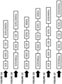
- the exhaust gas treatment systems are represented by the configurations shown in FIGs. 1A-1D .
- an exhaust gas stream containing gaseous pollutants e.g., particulate matter, unburned hydrocarbons, carbon monoxide, nitrogen oxides
- gaseous pollutants e.g., particulate matter, unburned hydrocarbons, carbon monoxide, nitrogen oxides
- the black arrow as shown, directly enters an upstream SCR or SCR/AMOx catalyst.
- the upstream SCR or upstream SCR/AMOx is in an underfloor position.
- the upstream SCR or upstream SCR/AMOx catalyst is in a "close-coupled” position.
- “close-coupled” positions are understood as generally intended in the art, i.e., being closer to the engine than in traditional "underfloor” positions (which are beneath the floor of a vehicle).
- close-coupled positions are within the engine compartment, i.e., beneath the hood of a vehicle, and adjacent to the exhaust manifold and, in such a position, close-coupled catalysts are commonly exposed to high temperature exhaust gas immediately exiting the engine after the engine has warmed up (and thus often serve to reduce hydrocarbon emissions during cold start, i.e., the period immediately following starting the engine from ambient conditions).
- the term "close-coupled" used to describe the upstream SCR or upstream SCR/AMOx means mounted close enough to the engine so as to leave enough space for, e.g., urea injection, fuel injection for active regeneration, etc.
- the upstream SCR or upstream SCR AMOx catalyst in the disclosed emission treatment systems is generally mounted just upstream of a DOC or zoned CSF.
- the exhaust gas treatment systems of the invention may comprise one or more downstream SCR catalysts or downstream SCR/AMOx catalysts to further reduce NOx emissions, as illustrated in FIG. 1 .
- typically reductant injectors are positioned just upstream (i.e., near the inlet) of the SCR or SCR/AMOx catalysts.
- a single reductant injector may suffice for the integrated catalyst components.
- FIG. 1A depicts a first/upstream SCR catalyst, followed by a downstream diesel oxidation catalyst (DOC), a downstream catalyzed soot filter (CSF), and a downstream SCR/AMOx catalyst.
- FIG. 1B depicts a first/upstream SCR/AMOx catalyst, followed by a downstream diesel oxidation catalyst (DOC), a downstream catalyzed soot filter (CSF), and a second, downstream SCR/AMOx catalyst.
- FIG. 1C depicts a first/upstream SCR catalyst, followed by a downstream diesel oxidation catalyst (DOC), a downstream catalyzed soot filter (CSF), a second, downstream SCR catalyst, and a downstream AMOx catalyst.
- FIG. 1D depicts a first/upstream SCR/AMOx catalyst, followed by a downstream diesel oxidation catalyst (DOC), a downstream catalyzed soot filter (CSF), a downstream SCR catalyst, and a downstream AMOx catalyst.
- FIG. 1E depicts a first/upstream SCR catalyst, followed by a downstream diesel oxidation catalyst (DOC), a downstream catalyzed soot filter (CSF), a downstream SCR catalyst, and a downstream SCR/AMOx catalyst.
- DOC diesel oxidation catalyst
- CSF downstream catalyzed soot filter
- Such catalysts within the disclosed exhaust gas treatment systems can be on separate substrates, or can be provided on a single substrate (e.g., in a zoned configuration).
- the catalyst compositions suitable for serving the desired purpose(s) can vary, as disclosed generally herein below.
- the upstream SCR catalyst or SCR/AMOx catalyst is in a close-coupled position (referred to herein as a "cc-SCR” catalyst or “cc-SCR/AMOx” catalyst).
- SCR selective catalytic reduction
- N 2 dinitrogen
- NO x nitrogen oxides
- the composition of the upstream SCR or SCR/AMOx catalyst can vary, as described herein below. Further, exemplary SCR and SCR/AMOx catalyst compositions are described in U.S. Patent Nos. 4,961,917 to Byrne and 5,516,497 to Speronello et al. , which are incorporated herein by reference in their entirety.
- the SCR catalyst can comprise, for example, one or more metal oxide (e.g., a mixed oxide), a molecular sieve (e.g., a metal-promoted molecular sieve), or combinations thereof.
- the upstream SCR catalyst comprises one or more molecular sieve materials.
- the SCR catalytic material comprises 8-member ring small pore molecular sieves containing a metal promoter.
- small pore refers to pore openings which are smaller than about 5 Angstroms (e.g., about 2-5 ⁇ , about 2-4 ⁇ , about 3-5 ⁇ , or about 3-4 ⁇ , for example on the order of ⁇ 3.8 Angstroms.
- One specific 8-member ring small pore molecular sieve is an 8-member ring small pore zeolite.
- the SCR catalytic material comprises a zeolite comprising a d6r unit.
- the SCR catalytic material comprises a zeolite having a structure type selected from AEI, AFT, AFX, CHA, EAB, EMT, ERI, FAU, GME, JSR, KFI, LEV, LTL, LTN, MOZ, MSO, MWW, OFF, SAS, SAT, SAV, SBS, SBT, SFW, SSF, SZR, TSC, WEN, and combinations thereof.
- the SCR catalytic material comprises a zeolite with a structure type selected from the group consisting of CHA, AEI, AFX, ERI, KFI, LEV, and combinations thereof.
- the SCR catalytic material comprises a zeolite with a structure type selected from CHA and AEI.
- the SCR catalytic material comprises a zeolite with the CHA structure type.
- the SCR catalytic material comprises zeolitic chabazite, which is a naturally occurring tectosilicate mineral of a zeolite group with an approximate formula represented by (Ca,Na 2 ,K 2 ,Mg)Al 2 Si 4 O 12 •6H 2 O (e.g., hydrated calcium aluminum silicate).
- zeolitic chabazite Three synthetic forms of zeolitic chabazite that may find use in the SCR catalysts disclosed herein are described in " Zeolite Molecular Sieves,"" by D. W. Breck, published in 1973 by John Wiley & Sons , which is hereby incorporated by reference. The three synthetic forms reported by Breck are Zeolite K-G, described in J. Chem.
- the ratio of silica to alumina in molecular sieves useful as SCR catalytic materials can vary over a wide range.
- molecular sieves useful as SCR catalytic materials have a silica to alumina molar ratio (SAR) in the range of 2 to 300, including 5 to 250; 5 to 200; 5 to 100; and 5 to 50.
- the molecular sieve has a silica to alumina molar ratio (SAR) in the range of 10 to 200, 10 to 100, 10 to 75, 10 to 60, 10 to 50, 15 to 100, 15 to 75, 15 to 60, 15 to 50, 20 to 100, 20 to 75, 20 to 60, and 20 to 50.
- the spherical particle of the molecular sieve has a particle size d50 in the range of about 1.0 to about 5 microns, and more specifically, about 1.0 to about 3.5 microns, and the individual crystals of a molecular sieve component have a crystal size in the range of about 100 to about 250 nm.
- Metal-promoted zeolite catalysts including, among others, iron-promoted and copper-promoted zeolite catalysts, for the selective catalytic reduction of nitrogen oxides with ammonia are also suitable.
- the promoter metal may be selected from Cu, Fe, Co, Ni, La, Ce, Mn, V, Ag, and combinations thereof. In specific embodiments, the promoter metal is Cu, Fe, or combinations thereof.
- Metal-promoted, particularly copper promoted aluminosilicate zeolites having the CHA structure type and a silica to alumina molar ratio greater than 1, have recently solicited a high degree of interest as catalysts for the SCR of oxides of nitrogen in lean burning engines using nitrogenous reductants.
- the promoter metal content in such catalysts, calculated as the oxide, is, in one or more embodiments, at least about 0.1 wt. %, reported on a volatile-free basis.
- the promoter metal comprises Cu, and the Cu content, calculated as CuO is in the range of up to about 10 wt. %, including 9, 8, 7, 6, 5, 4, 3, 2, 1, 0.5, and 0.1 wt. %, in each case based on the total weight of the calcined zeolite component reported on a volatile free basis.
- the Cu content, calculated as CuO is in the range of about 1 to about 4 wt. %.
- the DOC comprises an upstream zone comprising platinum and palladium on alumina (e.g., having about a 1:1 ratio), with a high metal loading (e.g., at least about 50 g/ft 3 ) and a downstream zone comprising platinum and palladium on alumina with a higher platinum content (e.g., having about a 5:1 Pt:Pd ratio) with a comparatively lower metal loading (e.g., about 20-24 g/ft 3 ).
- Exemplary DOC compositions suitable for use in the disclosed systems are described, for example, in U.S. Patent Nos. 7,078,004 to Voss et al. and 9,333,490 to Kazi et al.
- the soot burning catalyst can be, e.g., an oxidation catalyst comprising one or more precious metal (PM) catalysts (platinum, palladium, and/or rhodium) to promote NO to NO 2 oxidation.
- the catalyst of the CSF comprises platinum and palladium on a refractory metal oxide support (e.g., alumina).
- the CSF comprises a washcoat comprising platinum and palladium supported on alumina in a 4:1 ratio with a loading of about 4 g/ft 3 on the filter substrate.
- the soot filter may be made of any suitable refractory material for substrates, as outlined herein below.
- the filter is advantageously a wall flow filter, defined as a flow-through substrate in which the exhaust gas in different parts of the substrate may communicate through the walls of the passages.
- the downstream SCR catalyst in certain exhaust gas treatment systems disclosed herein can comprise any catalyst material suitable for NOx conversion, e.g., as described above with respect to the upstream SCR catalyst.
- the downstream SCR comprises a metal-promoted molecular sieve, e.g., including, but not limited to, Cu-CHA and/or Fe-CHA.
- the downstream SCR catalyst comprises pure Cu-CHA, pure Fe-CHA, or mixtures of Cu-CHA and Fe-CHA in the same washcoat. If desired, the downstream SCR catalyst may comprise Fe-CHA layered on top of Cu-CHA. In one particular embodiment, the downstream SCR is zoned with two or more catalyst compositions.
- the downstream SCR can be provided as a catalyst composite, comprising a catalytic coating, wherein the catalytic coating comprises an inlet zone containing Fe-CHA and an outlet zone containing Cu-CHA.
- Fe-Beta zeolite may be used in the place of the Fe-CHA in the above-mentioned downstream SCR catalysts, but this invention recognizes that Fe-Beta zeolite may be more susceptible to hydrocarbon absorption than CHA, due to its smaller structural ring size.
- the downstream AMOx catalyst in certain exhaust gas treatment systems disclosed herein can have the same composition or a different composition than the AMOx component of the optional upstream integrated SCR/AMOx catalyst. Again, any composition suitable for promoting the reaction of NH 3 with oxygen to produce NO, NO 2 , N 2 O, or preferably N 2 can be used at this position.
- the downstream AMOx comprises platinum on alumina.
- downstream AMOx is, instead, combined with an additional SCR catalyst, such that the exhaust gas stream exiting the DOC flows to the SCR1 catalyst, and then from the SCR1 catalyst to an integrated SCR/AMOx catalyst. See, e.g., the exhaust gas treatment system configurations in FIGs. 1E and 1F .
- the foregoing catalyst are typically supported on one or more substrates, providing one or more catalyst composites (i.e., catalytic materials in one or more layers on a substrate).
- a dispersion of any one or more of the catalytic materials as described herein may be used to form a slurry for a washcoat.
- To the slurry may be added any desired additional ingredients such as other platinum group metals, other supports, other stabilizers and promoters, and the like.
- Any two or more of the catalysts disclosed above can be combined on a single substrate, or can be provided as a single coated substrate.
- the substrate(s) for the catalyst compositions described herein above may be constructed of any material typically used for preparing automotive catalysts and will typically comprise a metal or ceramic honeycomb structure.
- the substrate typically provides a plurality of wall surfaces upon which a catalyst washcoat composition is applied and adhered, thereby acting as a carrier for the catalyst composition.
- Exemplary metallic substrates include those comprising heat resistant metals and metal alloys, such as titanium and stainless steel as well as other alloys in which iron is a substantial or major component.
- Such alloys may contain one or more of nickel, chromium, and/or aluminum, and the total amount of these metals may advantageously comprise at least 15 wt. % of the alloy, e.g., 10-25 wt. % of chromium, 3-8 wt. % of aluminum, and up to 20 wt. % of nickel.
- the alloys may also contain small or trace amounts of one or more other metals, such as manganese, copper, vanadium, titanium and the like.
- the surface or the metallic substrates may be oxidized at high temperatures, e.g., 700°C and higher, to form an oxide layer on the surface of the substrate, improving the corrosion resistance of the alloy and facilitating adhesion of the washcoat layer to the metal surface.
- Ceramic materials used to construct the substrate may include any suitable refractory material, e.g., cordierite, mullite, cordierite- ⁇ alumina, silicon nitride, zircon mullite, spodumene, alumina-silica magnesia, zircon silicate, sillimanite, magnesium silicates, zircon, petalite, ⁇ alumina, aluminosilicates and the like.
- suitable refractory material e.g., cordierite, mullite, cordierite- ⁇ alumina, silicon nitride, zircon mullite, spodumene, alumina-silica magnesia, zircon silicate, sillimanite, magnesium silicates, zircon, petalite, ⁇ alumina, aluminosilicates and the like.
- any suitable substrate may be employed, such as a monolithic flow-through substrate having a plurality of fine, parallel gas flow passages extending from an inlet to an outlet face of the substrate such that passages are open to fluid flow.
- the passages which are essentially straight paths from the inlet to the outlet, are defined by walls on which the catalytic material is coated as a washcoat so that the gases flowing through the passages contact the catalytic material.
- the flow passages of the monolithic substrate are thinwalled channels which can be of any suitable cross-sectional shape, such as trapezoidal, rectangular, square, sinusoidal, hexagonal, oval, circular, and the like.
- Such structures may contain from about 60 to about 1200 or more gas inlet openings (i.e., "cells") per square inch of cross section (cpsi), more usually from about 300 to 600 cpsi.
- the wall thickness of flow-through substrates can vary, with a typical range being between 0.002 and 0.1 inches.
- a representative commercially-available flow-through substrate is a cordierite substrate having 400 cpsi and a wall thickness of 6 mil (0.006 inches), or 600 cpsi and a wall thickness of 4 mil (0.004 inches).
- the invention is not limited to a particular substrate type, material, or geometry.
- the substrate may be a wall-flow substrate, wherein each passage is blocked at one end of the substrate body with a non-porous plug, with alternate passages blocked at opposite end-faces. This requires that gas entering the front or inlet end of the substrate to flow through the porous walls of the wall-flow substrate in order to exit the outlet end of the substrate.
- Such monolithic substrates may contain up to about 700 or more cpsi, such as about 100 to 400 cpsi and more typically about 200 to about 300 cpsi.
- the cross-sectional shape of the cells can vary as described above.
- Wall-flow substrates typically have a wall thickness between 0.002 and 0.1 inches.
- a representative commercially available wall-flow substrate is constructed from a porous cordierite, an example of which has 200 cpsi and 10 mil wall thickness or 300 cpsi with 8 mil wall thickness, and wall porosity between 45-65%.
- Other ceramic materials such as aluminum-titanate, silicon carbide and silicon nitride are also used as wall-flow filter substrates.
- the invention is not limited to a particular substrate type, material, or geometry. Note that where the substrate is a wall-flow substrate, the catalyst composition can permeate into the pore structure of the porous walls (i.e., partially or fully occluding the pore openings) in addition to being disposed on the surface of the walls.
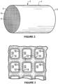
- FIGS. 2 and 3 illustrate an exemplary substrate 2 in the form of a flow-through substrate coated with a catalyst composition as described herein.
- the exemplary substrate 2 has a cylindrical shape and a cylindrical outer surface 4 , an upstream end face 6 and a corresponding downstream end face 8 , which is identical to end face 6.
- Substrate 2 has a plurality of fine, parallel gas flow passages 10 formed therein.
- flow passages 10 are formed by walls 12 and extend through carrier 2 from upstream end face 6 to downstream end face 8 , the passages 10 being unobstructed so as to permit the flow of a fluid, e.g., a gas stream, longitudinally through carrier 2 via gas flow passages 10 thereof.
- the oxidation catalyst of the invention can also be zone-coated on the substrate, meaning the oxidation catalyst is present only in an inlet zone or an outlet zone of the substrate, typically in combination with a second catalyst material of a different composition in the other zone. Any number or arrangement of coated zones is possible.
- FIG. 4 illustrates an exemplary substrate 2 in the form a wall flow filter substrate coated with a washcoat composition as described herein.
- the exemplary substrate 2 has a plurality of passages 52.
- the passages are tubularly enclosed by the internal walls 53 of the filter substrate.
- the substrate has an inlet end 54 and an outlet end 56. Alternate passages are plugged at the inlet end with inlet plugs 58 and at the outlet end with outlet plugs 60 to form opposing checkerboard patterns at the inlet 54 and outlet 56.
- a gas stream 62 enters through the unplugged channel inlet 64 , is stopped by outlet plug 60 and diffuses through channel walls 53 (which are porous) to the outlet side 66.
- the gas cannot pass back to the inlet side of walls because of inlet plugs 58.
- the porous wall flow filter used in this disclosure is catalyzed in that the wall of said substrate has thereon or contained therein one or more catalytic materials.
- Catalytic materials may be present on the inlet side of the substrate wall alone, the outlet side alone, or both the inlet and outlet sides.
- This disclosure includes the use of one or more layers of catalytic material within the wall as well as on the inlet and/or outlet walls of the substrate.
- the substrate can be coated at least twice with two separate washcoat slurries in an axially zoned configuration.
- the same substrate can be coated once with one washcoat slurry and a second time with another slurry, wherein each washcoat is different.
- the two separate washcoats may include separate catalyst compositions (i.e., a first catalyst composition and a second catalyst composition) or catalyst components of the same catalyst composition.
- one catalyst component may be coated first from the substrate inlet end (giving a "first washcoat zone"), and another catalyst component may be coated second from the substrate outlet end (giving a "second washcoat zone").
- one catalyst component may be coated first from the substrate outlet end (giving a "second washcoat zone”), and another catalyst component may be coated second from the substrate inlet end (giving a "first washcoat zone”).
- the first washcoat zone of specific embodiments extends from the front or inlet end of the substrate through the range of about 5% to about 95%, from about 5% to about 75%, from about 5% to about 50%, or from about 10% to about 35% of the length of the substrate.
- the second washcoat zone extends from the rear of outlet end of the substrate from about 5% about 95%, from about 5% to about 75%, from about 5% to about 50%, or from about 10% to about 35% of the total axial length of the substrate.
- the second washcoat zone in some embodiments, at least partially overlaps the first washcoat zone.
- the first washcoat zone in some embodiments, at least partially overlaps the second washcoat zone. In other embodiments, there is no significant overlap between the two washcoat zones.
- the substrate can be coated with two types of washcoat slurries in two separate zones, wherein a first washcoat zone including a washcoat of a first catalyst composition or first catalyst component and a second washcoat zone including a washcoat of a second catalyst composition or second catalyst component are located side by side along the length of the substrate, with no overlap of the zones.
- the total loading of the catalyst composition (including both impregnated metals and support material) on the catalyst substrate, such as a monolithic flow-through substrate, is typically from about 0.5 to about 6 g/in 3 , and more typically from about 1 to about 5 g/in 3 .
- Total loadings of individual catalytic components in the catalysts disclosed herein above are generally known to one of skill in the art. It is noted that these weights per unit volume are typically calculated by weighing the catalyst substrate before and after treatment with the catalyst washcoat composition, and since the treatment process involves drying and calcining the catalyst substrate at high temperature, these weights represent an essentially solvent-free catalyst coating as essentially all of the water of the washcoat slurry has been removed.
- Preparation of metal-impregnated support materials typically comprises impregnating a support material in particulate form with a metal solution, such as (in the context of PGM-containing catalysts) one or more of a platinum solution and a palladium solution.
- a metal solution such as (in the context of PGM-containing catalysts) one or more of a platinum solution and a palladium solution.
- Multiple metal components e.g., platinum and palladium
- the support particles are typically dry enough to absorb substantially all of the solution to form a moist solid.
- FIGs. 5A Comparative System A, below
- 5B Inventive System B, below
- 5C Inventive System C, below
- All testing was conducted on a 13 liter HDD diesel engine on-road, and system components were aged 50 hours at 650 °C before testing. Testing for this Example was run over transient cycles (8 FTPs and 6 WHTCs) with 20 minutes soaks between cycles.
- a comparative exhaust system similar to the System of Example 1 was prepared with the general structure shown in FIG. 5A , having a close-coupled DOC, followed by a downstream CSF, a downstream SCR (“SCR1”) catalyst, and a downstream SCR/AMOx catalyst.
- the DOC was a flow-thru DOC coated onto a 13" ⁇ 6" flow-thru substrate with 400 cpsi and 4 mil wall thickness. It was formulated with Pt and Pd on alumina.
- the DOC was zoned, with an inlet zone that was 33% of the total catalyst length (i.e., 2") and designed for fuel L/O function for active regeneration.
- the DOC had a 60 g/ft 3 Pt and Pd at a 1:1 ratio.
- the rear zone 67% of the catalyst length (i.e. 4") was for oxidizing NO to NO 2 and had 30 g/ft 3 Pt and Pd at 5:1 ratio.
- the overall platinum-group metal loading on this DOC was 40g/ft 3 (2:1 ratio).
- the CSF was a 13" ⁇ 7" filter substrate with 300 cpsi and a 9 mil wall thickness.
- the filter substrate was coated with 4 g/ft 3 Pt and Pd at 4:1 ratio supported on alumina.
- the SCR1 catalyst contained a Fe/Cu-CHA zoned SCR, having a 3" inlet zone of Fe-CHA (2.35% Fe 2 O 3 ) and a 3.5" outlet zone of Cu-CHA (2.35% CuO).
- the dry gain (DG) in each zone was 2.5 g/in 3 .
- the SCR/AMOx was a 13" ⁇ 5.5" flow-thru substrate with 600 cpsi and a 3 mil wall thickness. It had a zoned SCR/AMOX configuration, with a 2" long rear AMOX bottom zone coat of Pt-only (2g/ft 3 in the zone) on alumina. It also had a full length SCR topcoat of Cu-chabazite (2.35% CuO) at 2.5g/in 3 DG loading, which also covered the rear AMOx zone.
- FTIRs SCR/AMOx-out (FT1), SCR1-out (FT2), and SCR/AMOx-out (FT3) and direct benches were set up at engine-out (D1) and tailpipe-out (D2).
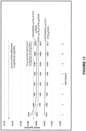
- the exhaust temperatures at SCR/AMOx-in and SCR1-in were analyzed, and it was found that the exhaust temperature to both SCR/AMOx and SCR1 over the initial stage of the cycle were quite low (around 190°C) and only reached their peak (around 350°C) in the latter stages of the FTP cycles, as shown in FIG. 14 .
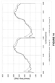
- the exhaust gas flow over time for this comparative system is shown in FIG. 15 .
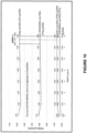
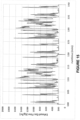
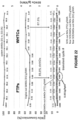
- the BSNOx and NOx conversion for this system were analyzed over the 8 HDDTs (FTPs) and 6 WHTCs as shown in FIG. 16 .
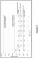
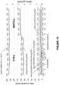
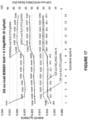
- BSN 2 O levels for this system are shown in FIG. 17 .
- the exhaust temperatures at the cc-SCR/AMOX-in are significantly higher than the downstream SCR-in and SCR/AMOX-in temperatures.
- one aspect of this invention is the recognition that a close-coupled SCR or close-coupled SCR/AMOX (in this example) is able to take advantage of these higher exhaust temperatures to achieve better NOx conversion.
- This system was found to have much lower tailpipe BSNOx due to inclusion of the inlet SCR/AMOx.
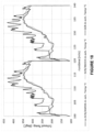
- BSN 2 O levels for this system are shown in FIG. 19 .
- Very low BSN 2 O levels were achieved over this system, as shown.
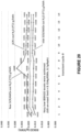
- BSN 2 O levels for this system are shown in FIG. 20 .
- This system was found to have essentially the same exhaust temperatures at the upstream SCR/AMOX-in as those of Inventive System B, but with a slight increase in exhaust temperature to the downstream SCR and SCR/AMOx, as shown in FIG. 21 . This is believed to be a result of the smaller (smaller thermal mass) of the 10.5" dia. zoned-CSF compared with the full size 13" dia. DOC + CSF.
- This system was found to have very low rear SCR/AMOx-out (tailpipe), approaching the California Air Resources Board (ARB) limits (0.02 g/bhph BSNOx), as shown in FIG. 22 .
- BSN 2 O levels for this system are shown in FIG. 23 . Very low BSN 2 O levels were again achieved over this system, which were well below the 0.134 g/KWh (0.1 g/bhph) U.S. on-road limit.
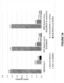
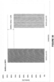
- FIG. 24 provides a comparison between BSNOx values at various positions within Comparative System A (shown as “HDD System”), Inventive System B ("HDD System w/ cc-SCR/AMOX”), and Inventive System C ("HDD System w/ cc-SCR/AMOX & zoned-CSF").
- the BSNOx value at SCR/AMOx-out (i.e., the tailpipe emission) of Inventive System B is significantly lower than that of Comparative System A (0.089 g/KWh v. 0.212 g/KWh).
- the BSNOx value at SCR/AMOx-out (i.e., the tailpipe emission) of Inventive System C is even lower, with a value of 0.062 g/KWh.
- This graph demonstrates the effectiveness of the inclusion of an upstream SCR component within the exhaust gas treatment system.
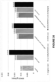
- FIG. 25 provides a similar comparison between BSNOx values at various positions within these systems in units of g/bhph, again demonstrating the effectiveness of the inclusion of a close-coupled (upstream) SCR component within the exhaust gas treatment system.
- the inclusion of a cc-SCR/AMOx catalyst resulted in a reduction in BSNOx at SCR/AMOx-out (i.e., the tailpipe emission) from 0.158 g/bhph to 0.066 g/bhph.
- the inclusion of a zoned CSF in place of the DOC-CSF further reduced the BSNOx at SCR/AMOx-out (i.e., the tailpipe emission) to 0.046 g/bhph.
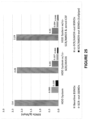
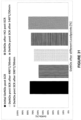
- FIG. 26 provides a comparison between BSN 2 O values at various positions within Comparative System A (shown as “HDD System”), Inventive System B ("HDD System w/ cc-SCR/AMOX”), and Inventive System C ("HDD System w/ cc-SCR/AMOX & zoned-CSF").
- the HDD system resulted in the production of more N 2 O, with a BSN 2 O value at SCR/AMOx-out (i.e., tailpipe emission) of 0.0194 g/bhph.
- cc-SCR/AMOx catalyst resulted in a significant decrease in BSN 2 O, giving a value at SCR/AMOx-out (i.e., tailpipe emission) of 0.0157 g/bhph.
- SCR/AMOx-out i.e., tailpipe emission
- BSN 2 O value at SCR/AMOx-out i.e., tailpipe emission
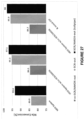
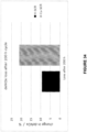
- FIG. 27 provides a comparison between NOx conversion percentages at various positions within Comparative System A (shown as “HDD System”), Inventive System B ("HDD System w/ cc-SCR/AMOX”), and Inventive System C ("HDD System w/ cc-SCR/AMOX & zoned-CSF").
- the HDD system provided a NOx conversion of 93.4% at SCR/AMOx-out (tailpipe emission).
- Both Inventive System B and Inventive System C outperformed Comparative System A in NOx reduction, providing a 97.1% NOx conversion and a 98% NOx conversion, respectively, at SCR/AMOx-out (tailpipe emission).
- Each system setup met the respective emissions targets at the tailpipe, with FTP target of 0.2 g/bhph, and the two inventive system setups approached ARB target levels (0.02 g/bhph). Each system setup further met the WHTC target of 0.46 g/KWh, EU, VI). Tailpipe BSN 2 O levels were very low for the inventive system setups as well, well below the 0.1 g/bhph on-road United States limit.
- a first, comparative system was provided, under fresh conditions, comprising an SCR/AMOX upstream of a standard Euro VI or US EPA 2010 aftertreatment system of DOC/CSF/SCR/AMOX.
- SO 3 (rather than SO 2 ) acts as a deactivation species, especially for zeolite-based SCR materials.
- the fraction of SO 3 entering the upstream SCR is significantly less than for the downstream SCR as it does not contain an oxidation catalyst upstream of it; however, the engine will, under normal operating conditions, still emit low concentrations of SO 3 .
- Deactivation of an upstream Cu-zeolite based SCR therefore commonly occurs over time, albeit at a slower rate compared to a downstream Cu-zeolite SCR.
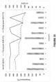
- An inventive system was provided, containing an upstream Cu-zeolite SCR over the hot FTP with an E.O. level of 1.9g/bhphr. Results were already meeting proposed ultra-low NOx (ULNOx) and N 2 O emissions over a hot FTP, albeit at fairly low engine-out NOx level but also using a non-optimized urea doing strategy for the upstream SCR catalyst. See FIG. 28 . As shown, the system containing an upstream SCR catalyst was able to achieve a deNOx level of 99.61% with exceptionally low NOx and N 2 O emissions concurrently.
- Desulfation of a Cu-zeolite SCR usually occurs at temperatures around 500°C.
- the SCR tends to be desulfated during filter regenerations, where temperatures are achieved which are sufficient to concurrently desulfate the Cu-zeolite SCR.
- An upstream Cu-zeolite SCR would still need to be desulfated after a certain time interval to maintain its NOx conversion performance, due, among other pathways, to deactivation via ammonium bisulfate formation.
- the only pathway to achieve a sufficient temperature over this component would, however, be via engine measures, as no HC oxidation catalyst would be available upstream to raise exhaust temperatures.
- a Cu-CHA SCR was studied with regard to the possibility of acting as an HC oxidation catalyst during hydrocarbon injection (HCI) events, and the impact a high concentration of HC would have on the Cu-CHA SCR's DeNOx performance was considered.
- the DOC was replaced with an SCR/AMOX (based on Cu-CHA) in an aftertreatment system.
- SCR/AMOX based on Cu-CHA
- Several load points with varying exhaust flow and inlet temperatures were targeted to simulate HCI events. It was apparent that, while the SCR catalyst portion did not show any significant HC oxidation capability, the AMOx was able to light-off the HC under certain conditions, due to the presence of PGM in this part. NOx conversion tests of the component prior to and post HCI events displayed a significant deactivation. See FIG. 30 .
- This SCR catalyst was based on a small pore zeolite structure (CHA), and HC still appears to deactivate the NOx conversion activity of this SCR.
- CHA small pore zeolite structure
- coke formation may be the underlying cause for this deactivation and subsequently 'decoking' load points were targeted to investigate under which conditions the performance could be recovered.
- the temperature was ramped up by 50°C intervals starting at 490°C and this temperature again maintained for 30 minutes. It became apparent, that the DeNOx Performance of the Cu-CHA SCR needs a temperature between 540 and 590°C for 30 minutes to fully recover its performance after HCI events. See FIG. 31 .
- the performance of the SCR catalyst was measured after each 'decoking event" of 30 minutes starting at 490°C and ramping it up by 50°C per 'decoking step'. It appears a temperature between 540 and 590°C for 30 minutes is needed for a full recovery. Recovery steps were run without urea dosing.
Landscapes
- Engineering & Computer Science (AREA)
- Chemical & Material Sciences (AREA)
- Chemical Kinetics & Catalysis (AREA)
- Combustion & Propulsion (AREA)
- Mechanical Engineering (AREA)
- General Engineering & Computer Science (AREA)
- Materials Engineering (AREA)
- Health & Medical Sciences (AREA)
- Toxicology (AREA)
- Organic Chemistry (AREA)
- Crystallography & Structural Chemistry (AREA)
- Exhaust Gas After Treatment (AREA)
- Catalysts (AREA)
- Exhaust Gas Treatment By Means Of Catalyst (AREA)
- Processes For Solid Components From Exhaust (AREA)
Applications Claiming Priority (3)
| Application Number | Priority Date | Filing Date | Title |
|---|---|---|---|
| US201862632322P | 2018-02-19 | 2018-02-19 | |
| PCT/IB2019/051301 WO2019159151A1 (en) | 2018-02-19 | 2019-02-18 | Exhaust gas treatment system with upstream scr catalyst |
| EP19754695.5A EP3755891A4 (de) | 2018-02-19 | 2019-02-18 | Abgasbehandlungssystem mit vorgeschaltetem scr-katalysator |
Related Parent Applications (1)
| Application Number | Title | Priority Date | Filing Date |
|---|---|---|---|
| EP19754695.5A Division EP3755891A4 (de) | 2018-02-19 | 2019-02-18 | Abgasbehandlungssystem mit vorgeschaltetem scr-katalysator |
Publications (2)
| Publication Number | Publication Date |
|---|---|
| EP4579067A2 true EP4579067A2 (de) | 2025-07-02 |
| EP4579067A3 EP4579067A3 (de) | 2025-08-13 |
Family
ID=67619774
Family Applications (2)
| Application Number | Title | Priority Date | Filing Date |
|---|---|---|---|
| EP19754695.5A Pending EP3755891A4 (de) | 2018-02-19 | 2019-02-18 | Abgasbehandlungssystem mit vorgeschaltetem scr-katalysator |
| EP25171325.1A Pending EP4579067A3 (de) | 2018-02-19 | 2019-02-18 | Abgasbehandlungssystem mit vorgeschaltetem scr-katalysator |
Family Applications Before (1)
| Application Number | Title | Priority Date | Filing Date |
|---|---|---|---|
| EP19754695.5A Pending EP3755891A4 (de) | 2018-02-19 | 2019-02-18 | Abgasbehandlungssystem mit vorgeschaltetem scr-katalysator |
Country Status (6)
| Country | Link |
|---|---|
| US (1) | US11268420B2 (de) |
| EP (2) | EP3755891A4 (de) |
| JP (2) | JP7584727B2 (de) |
| KR (1) | KR102743005B1 (de) |
| CN (1) | CN111742121B (de) |
| WO (1) | WO2019159151A1 (de) |
Families Citing this family (26)
| Publication number | Priority date | Publication date | Assignee | Title |
|---|---|---|---|---|
| JP2021080876A (ja) * | 2019-11-19 | 2021-05-27 | 日野自動車株式会社 | 排気浄化装置 |
| JP2021080875A (ja) * | 2019-11-19 | 2021-05-27 | 日野自動車株式会社 | 排気浄化装置 |
| KR20230013248A (ko) * | 2020-05-14 | 2023-01-26 | 바스프 코포레이션 | 금속 산화물계 scr 촉매 조성물 |
| EP3915679A1 (de) * | 2020-05-26 | 2021-12-01 | UMICORE AG & Co. KG | Katalysator, katalysatorsystem und abgasreinigungssystem zur reduzierung von ammoniak-emissionen |
| JP2023529934A (ja) | 2020-06-12 | 2023-07-12 | ビーエーエスエフ コーポレーション | 多機能触媒を備えた排ガス処理システム |
| US11326493B2 (en) | 2020-07-21 | 2022-05-10 | Paccar Inc | Ammonia storage capacity of SCR catalyst unit |
| US11428136B2 (en) | 2020-07-21 | 2022-08-30 | Paccar Inc | Heater diagnostics in heavy-duty motor vehicle engines |
| US11725560B2 (en) | 2020-07-21 | 2023-08-15 | Paccar Inc | Heater control in heavy-duty motor vehicle engines |
| US11879367B2 (en) | 2020-07-21 | 2024-01-23 | Paccar Inc | NOx sensor diagnostics in heavy-duty motor vehicle engines |
| US11352927B2 (en) | 2020-07-21 | 2022-06-07 | Paccar Inc | Control of selective catalytic reduction in heavy-duty motor vehicle engines |
| US11976582B2 (en) | 2020-07-21 | 2024-05-07 | Paccar Inc | Methods for diagnostics and operation of an emissions aftertreatment system |
| US11499463B2 (en) | 2020-07-21 | 2022-11-15 | Paccar Inc | Methods for evaluating diesel exhaust fluid quality |
| US11181026B1 (en) * | 2020-07-21 | 2021-11-23 | Paccar Inc | Methods for operation of an emissions aftertreatment system for NOx control during regeneration of diesel particulate filter |
| KR20230116923A (ko) * | 2020-12-08 | 2023-08-04 | 바스프 코포레이션 | 다기능 촉매를 포함하는 배기 가스 처리 시스템 |
| WO2022216658A1 (en) * | 2021-04-05 | 2022-10-13 | Corning Incorporated | Exhaust treatment method and apparatus having particulate filters and scr |
| WO2023081094A1 (en) * | 2021-11-04 | 2023-05-11 | University Of Washington | Novel spirocyclic compounds as klhdc2 ligands |
| AT525550B1 (de) * | 2021-12-10 | 2023-05-15 | Avl List Gmbh | Verbrennungsmotorsystem mit einem Ammoniak-Verbrennungsmotor und daran angeschlossener Abgasreinigungsanlage und Betriebsverfahren hierfür |
| CN114622971B (zh) * | 2022-03-25 | 2023-01-13 | 惠州市瑞合环保科技有限公司 | 一种用于氢内燃机的后处理系统及其制备方法 |
| GB2618152B (en) * | 2022-04-29 | 2024-10-30 | Perkins Engines Co Ltd | Aftertreatment for ammonia fuelled engine |
| WO2024029290A1 (ja) * | 2022-08-04 | 2024-02-08 | エヌ・イーケムキャット株式会社 | 排ガス処理用システム |
| DE102022132122A1 (de) * | 2022-12-05 | 2024-06-06 | Purem GmbH | Abgasbehandlungsanordnung |
| DE102022132123A1 (de) * | 2022-12-05 | 2024-06-06 | Purem GmbH | Abgasbehandlungsanordnung |
| AT526941B1 (de) | 2023-05-25 | 2024-09-15 | Avl List Gmbh | Verfahren zur Reinigung von Abgas eines Verbrennungsmotors und Abgasreinigungsanlage hierfür |
| EP4646528B1 (de) | 2023-06-01 | 2026-02-04 | Johnson Matthey Public Limited Company | System zur behandlung eines abgases |
| AT527282B1 (de) * | 2023-06-05 | 2025-02-15 | Avl List Gmbh | Verfahren zur Reinigung von Abgas eines Kraftfahrzeugverbrennungsmotors und Abgasreinigungsanlage hierfür |
| WO2026073012A1 (en) * | 2024-09-27 | 2026-04-02 | Basf Mobile Emissions Catalysts Llc | Lev zeolite compositions for selective catalytic reduction |
Citations (35)
| Publication number | Priority date | Publication date | Assignee | Title |
|---|---|---|---|---|
| GB868846A (en) | 1957-08-26 | 1961-05-25 | Union Carbide Corp | Improvements in and relating to zeolites |
| US3030181A (en) | 1957-08-26 | 1962-04-17 | Union Carbide Corp | Crystalline zeolite r |
| US4010238A (en) | 1973-03-26 | 1977-03-01 | Sumitomo Chemical Company, Limited | Proces for selective removal of nitrogen oxides from waste gases |
| US4085193A (en) | 1973-12-12 | 1978-04-18 | Mitsubishi Petrochemical Co. Ltd. | Catalytic process for reducing nitrogen oxides to nitrogen |
| US4221768A (en) | 1976-04-08 | 1980-09-09 | Nippon Shokubai Kagaku Kogyo Co., Ltd. | Catalyst for purifying exhaust and waste gases |
| US4440871A (en) | 1982-07-26 | 1984-04-03 | Union Carbide Corporation | Crystalline silicoaluminophosphates |
| US4518710A (en) | 1984-01-25 | 1985-05-21 | Uop Inc. | Catalyst for the reduction of nitrogen oxides in gaseous mixtures and method of making the catalyst |
| US4544538A (en) | 1982-07-09 | 1985-10-01 | Chevron Research Company | Zeolite SSZ-13 and its method of preparation |
| US4782039A (en) | 1986-05-19 | 1988-11-01 | Johnson Matthey, Inc. | Selective catalytic reduction catalyst and a process for preparing the catalyst |
| US4961917A (en) | 1989-04-20 | 1990-10-09 | Engelhard Corporation | Method for reduction of nitrogen oxides with ammonia using promoted zeolite catalysts |
| US5137855A (en) | 1988-06-09 | 1992-08-11 | W. R. Grace & Co.-Conn. | Catalysts for selective catalytic reduction denox technology |
| US5476828A (en) | 1991-07-29 | 1995-12-19 | British Technology Group Limited | Catalyst and catalytic reduction |
| US5516497A (en) | 1989-04-20 | 1996-05-14 | Engelhard Corporation | Staged metal-promoted zeolite catalysts and method for catalytic reduction of nitrogen oxides using the same |
| US6162415A (en) | 1997-10-14 | 2000-12-19 | Exxon Chemical Patents Inc. | Synthesis of SAPO-44 |
| US6171556B1 (en) | 1992-11-12 | 2001-01-09 | Engelhard Corporation | Method and apparatus for treating an engine exhaust gas stream |
| US20010049339A1 (en) | 2000-04-11 | 2001-12-06 | Adolf Schafer-Sindlinger | Process for the preparation of a vanadia SCR-catalyst supported on titania |
| US7078004B2 (en) | 1999-07-02 | 2006-07-18 | Engelhard Corporation | Diesel oxidation catalyst |
| US7264789B1 (en) | 1998-07-29 | 2007-09-04 | Exxonmobil Chemical Patents Inc. | Crystalline molecular sieves |
| WO2009074308A1 (en) | 2007-12-10 | 2009-06-18 | Hte Aktiengesellschaft The High Throughput Experimentation Company | Oxidation catalzyst containing pt and pd |
| WO2010121280A1 (en) | 2009-04-23 | 2010-10-28 | Treibacher Industrie Ag | Transition-metal vanadate or mixed transition-metal / rare earth vanadate based catalyst composition for selective catalytic reduction of exhaust gases |
| US8283182B2 (en) | 2003-03-18 | 2012-10-09 | Platform Diagnostics Limited | Agglutination based sample testing device |
| US8524185B2 (en) | 2008-11-03 | 2013-09-03 | Basf Corporation | Integrated SCR and AMOx catalyst systems |
| US8685882B2 (en) | 2005-09-27 | 2014-04-01 | Korea Power Engineering Company, Inc. | Vanadium/titania catalyst comprising natural manganese ore for removing nitrogen oxides and dioxin in wide operating temperature range and method of using the same |
| US8800268B2 (en) | 2006-12-01 | 2014-08-12 | Basf Corporation | Zone coated filter, emission treatment systems and methods |
| US8858904B2 (en) | 2010-02-23 | 2014-10-14 | Basf Corporation | Catalyzed soot filter |
| US8975206B2 (en) | 2010-04-16 | 2015-03-10 | Treibacher Industrie Ag | Catalyst composition for selective catalytic reduction of exhaust gases |
| US9101908B2 (en) | 2012-07-13 | 2015-08-11 | Korea Institute Of Science And Technology | Vanadia—titania catalyst for removing nitrogen oxides and method for manufacturing the same |
| WO2015130211A1 (en) | 2014-02-28 | 2015-09-03 | Scania Cv Ab | Exhaust treatment system and method for treatment of an exhaust stream |
| US9333490B2 (en) | 2013-03-14 | 2016-05-10 | Basf Corporation | Zoned catalyst for diesel applications |
| WO2017019958A1 (en) | 2015-07-30 | 2017-02-02 | Basf Corporation | Diesel oxidation catalyst |
| WO2017101449A1 (en) | 2015-12-17 | 2017-06-22 | Basf Corporation | Selective catalytic reduction (scr) catalyst comprising a composite oxide containing v and sb, preparation process thereof, and use thereof for nitrogen oxides removal |
| US20170341026A1 (en) | 2016-05-31 | 2017-11-30 | Johnson Matthey Public Limited Company | Vanadium Catalysts for High Engine-Out NO2 Systems |
| WO2017216728A1 (en) | 2016-06-17 | 2017-12-21 | Basf Corporation | Palladium diesel oxidation catalyst |
| WO2018025208A1 (en) | 2016-08-04 | 2018-02-08 | Basf Corporation | Oxidation catalyst comprising sulfur compound |
| WO2018029016A1 (en) | 2016-08-08 | 2018-02-15 | Electrolux Appliances Aktiebolag | Method for controlling an induction hob |
Family Cites Families (23)
| Publication number | Priority date | Publication date | Assignee | Title |
|---|---|---|---|---|
| US7264785B2 (en) | 2001-12-20 | 2007-09-04 | Johnson Matthey Public Limited Company | Selective catalytic reduction |
| US20080127638A1 (en) * | 2006-12-01 | 2008-06-05 | Marius Vaarkamp | Emission Treatment Systems and Methods |
| CN101600857B (zh) * | 2006-12-01 | 2012-08-29 | 巴斯福催化剂公司 | 分区涂布的过滤器、排放物处理系统和方法 |
| US7799289B2 (en) * | 2007-07-31 | 2010-09-21 | Caterpillar Inc | Exhaust treatment system with NO2 control |
| EP2230001A1 (de) * | 2009-03-18 | 2010-09-22 | Nederlandse Organisatie voor toegepast -natuurwetenschappelijk onderzoek TNO | Abgasbehandlung |
| US9453443B2 (en) | 2009-03-20 | 2016-09-27 | Basf Corporation | Emissions treatment system with lean NOx trap |
| US8293182B2 (en) | 2010-05-05 | 2012-10-23 | Basf Corporation | Integrated SCR and AMOx catalyst systems |
| WO2012051273A1 (en) | 2010-10-13 | 2012-04-19 | Cummins Intellectual Property, Inc. | Multi-leg exhaust aftertreatment system and method |
| WO2013060341A1 (en) * | 2011-10-24 | 2013-05-02 | Haldor Topsøe A/S | Catalyst composition for use in selective catalytic reduction of nitrogen oxides |
| HRP20211668T1 (hr) * | 2011-11-22 | 2022-02-18 | Deutz Aktiengesellschaft | Postupak i uređaj za čišćenje ispušnih plinova dizel motora |
| WO2013095214A1 (en) * | 2011-12-23 | 2013-06-27 | Volvo Lastvagnar Ab | Exhaust aftertreatment system and method for operating the system |
| JP2014101778A (ja) * | 2012-11-19 | 2014-06-05 | Toyota Industries Corp | 排気ガス浄化装置 |
| US20140331644A1 (en) | 2013-05-08 | 2014-11-13 | Cummins Ip, Inc. | Exhaust aftertreatment component condition estimation and regeneration |
| US9517457B2 (en) | 2013-10-30 | 2016-12-13 | Cummins Inc. | Aftertreatment systems with reduced N2O generation |
| RU2687854C2 (ru) * | 2014-02-28 | 2019-05-16 | Юмикор АГ унд Ко. КГ | Способ очистки выхлопного газа двигателя с воспламенением от сжатия |
| US20160032803A1 (en) * | 2014-07-29 | 2016-02-04 | Tenneco Automotive Operating Company Inc. | Exhaust After-treatment System Having Low Temperature SCR Catalyst |
| GB2540832B (en) * | 2015-02-20 | 2019-04-17 | Johnson Matthey Plc | Bi-metal molecular sieve catalysts |
| US12203403B2 (en) * | 2015-03-19 | 2025-01-21 | Basf Mobile Emissions Catalysts Llc | Filter catalyzed with SCR catalyst, systems and methods |
| CN107847863B (zh) * | 2015-06-18 | 2021-08-27 | 庄信万丰股份有限公司 | 分区的排气系统 |
| US9616385B1 (en) * | 2015-09-30 | 2017-04-11 | Deere & Company | System and method for regulating exhaust emissions |
| KR20240103063A (ko) | 2016-05-11 | 2024-07-03 | 바스프 코포레이션 | 유도 가열용으로 적합한 자성 물질을 포함하는 촉매 조성물 |
| US10718245B2 (en) * | 2018-06-13 | 2020-07-21 | Deere & Company | Exhaust gas treatment system and method having improved low temperature performance |
| US11008917B2 (en) * | 2018-08-24 | 2021-05-18 | International Engine Intellectual Property Company, Llc. | DEF dosing using multiple dosing locations while maintaining high passive soot oxidation |
-
2019
- 2019-02-18 JP JP2020566345A patent/JP7584727B2/ja active Active
- 2019-02-18 EP EP19754695.5A patent/EP3755891A4/de active Pending
- 2019-02-18 WO PCT/IB2019/051301 patent/WO2019159151A1/en not_active Ceased
- 2019-02-18 EP EP25171325.1A patent/EP4579067A3/de active Pending
- 2019-02-18 US US16/971,236 patent/US11268420B2/en active Active
- 2019-02-18 KR KR1020207023732A patent/KR102743005B1/ko active Active
- 2019-02-18 CN CN201980013906.8A patent/CN111742121B/zh active Active
-
2024
- 2024-02-09 JP JP2024018380A patent/JP2024059685A/ja active Pending
Patent Citations (35)
| Publication number | Priority date | Publication date | Assignee | Title |
|---|---|---|---|---|
| GB868846A (en) | 1957-08-26 | 1961-05-25 | Union Carbide Corp | Improvements in and relating to zeolites |
| US3030181A (en) | 1957-08-26 | 1962-04-17 | Union Carbide Corp | Crystalline zeolite r |
| US4010238A (en) | 1973-03-26 | 1977-03-01 | Sumitomo Chemical Company, Limited | Proces for selective removal of nitrogen oxides from waste gases |
| US4085193A (en) | 1973-12-12 | 1978-04-18 | Mitsubishi Petrochemical Co. Ltd. | Catalytic process for reducing nitrogen oxides to nitrogen |
| US4221768A (en) | 1976-04-08 | 1980-09-09 | Nippon Shokubai Kagaku Kogyo Co., Ltd. | Catalyst for purifying exhaust and waste gases |
| US4544538A (en) | 1982-07-09 | 1985-10-01 | Chevron Research Company | Zeolite SSZ-13 and its method of preparation |
| US4440871A (en) | 1982-07-26 | 1984-04-03 | Union Carbide Corporation | Crystalline silicoaluminophosphates |
| US4518710A (en) | 1984-01-25 | 1985-05-21 | Uop Inc. | Catalyst for the reduction of nitrogen oxides in gaseous mixtures and method of making the catalyst |
| US4782039A (en) | 1986-05-19 | 1988-11-01 | Johnson Matthey, Inc. | Selective catalytic reduction catalyst and a process for preparing the catalyst |
| US5137855A (en) | 1988-06-09 | 1992-08-11 | W. R. Grace & Co.-Conn. | Catalysts for selective catalytic reduction denox technology |
| US4961917A (en) | 1989-04-20 | 1990-10-09 | Engelhard Corporation | Method for reduction of nitrogen oxides with ammonia using promoted zeolite catalysts |
| US5516497A (en) | 1989-04-20 | 1996-05-14 | Engelhard Corporation | Staged metal-promoted zeolite catalysts and method for catalytic reduction of nitrogen oxides using the same |
| US5476828A (en) | 1991-07-29 | 1995-12-19 | British Technology Group Limited | Catalyst and catalytic reduction |
| US6171556B1 (en) | 1992-11-12 | 2001-01-09 | Engelhard Corporation | Method and apparatus for treating an engine exhaust gas stream |
| US6162415A (en) | 1997-10-14 | 2000-12-19 | Exxon Chemical Patents Inc. | Synthesis of SAPO-44 |
| US7264789B1 (en) | 1998-07-29 | 2007-09-04 | Exxonmobil Chemical Patents Inc. | Crystalline molecular sieves |
| US7078004B2 (en) | 1999-07-02 | 2006-07-18 | Engelhard Corporation | Diesel oxidation catalyst |
| US20010049339A1 (en) | 2000-04-11 | 2001-12-06 | Adolf Schafer-Sindlinger | Process for the preparation of a vanadia SCR-catalyst supported on titania |
| US8283182B2 (en) | 2003-03-18 | 2012-10-09 | Platform Diagnostics Limited | Agglutination based sample testing device |
| US8685882B2 (en) | 2005-09-27 | 2014-04-01 | Korea Power Engineering Company, Inc. | Vanadium/titania catalyst comprising natural manganese ore for removing nitrogen oxides and dioxin in wide operating temperature range and method of using the same |
| US8800268B2 (en) | 2006-12-01 | 2014-08-12 | Basf Corporation | Zone coated filter, emission treatment systems and methods |
| WO2009074308A1 (en) | 2007-12-10 | 2009-06-18 | Hte Aktiengesellschaft The High Throughput Experimentation Company | Oxidation catalzyst containing pt and pd |
| US8524185B2 (en) | 2008-11-03 | 2013-09-03 | Basf Corporation | Integrated SCR and AMOx catalyst systems |
| WO2010121280A1 (en) | 2009-04-23 | 2010-10-28 | Treibacher Industrie Ag | Transition-metal vanadate or mixed transition-metal / rare earth vanadate based catalyst composition for selective catalytic reduction of exhaust gases |
| US8858904B2 (en) | 2010-02-23 | 2014-10-14 | Basf Corporation | Catalyzed soot filter |
| US8975206B2 (en) | 2010-04-16 | 2015-03-10 | Treibacher Industrie Ag | Catalyst composition for selective catalytic reduction of exhaust gases |
| US9101908B2 (en) | 2012-07-13 | 2015-08-11 | Korea Institute Of Science And Technology | Vanadia—titania catalyst for removing nitrogen oxides and method for manufacturing the same |
| US9333490B2 (en) | 2013-03-14 | 2016-05-10 | Basf Corporation | Zoned catalyst for diesel applications |
| WO2015130211A1 (en) | 2014-02-28 | 2015-09-03 | Scania Cv Ab | Exhaust treatment system and method for treatment of an exhaust stream |
| WO2017019958A1 (en) | 2015-07-30 | 2017-02-02 | Basf Corporation | Diesel oxidation catalyst |
| WO2017101449A1 (en) | 2015-12-17 | 2017-06-22 | Basf Corporation | Selective catalytic reduction (scr) catalyst comprising a composite oxide containing v and sb, preparation process thereof, and use thereof for nitrogen oxides removal |
| US20170341026A1 (en) | 2016-05-31 | 2017-11-30 | Johnson Matthey Public Limited Company | Vanadium Catalysts for High Engine-Out NO2 Systems |
| WO2017216728A1 (en) | 2016-06-17 | 2017-12-21 | Basf Corporation | Palladium diesel oxidation catalyst |
| WO2018025208A1 (en) | 2016-08-04 | 2018-02-08 | Basf Corporation | Oxidation catalyst comprising sulfur compound |
| WO2018029016A1 (en) | 2016-08-08 | 2018-02-15 | Electrolux Appliances Aktiebolag | Method for controlling an induction hob |
Non-Patent Citations (2)
| Title |
|---|
| "Zeolite Molecular Sieves", 1973, JOHN WILEY & SONS |
| BRECKZEOLITE K-G: "J. Chem. Soc", 1956, pages: 2822 |
Also Published As
| Publication number | Publication date |
|---|---|
| CN111742121B (zh) | 2022-08-16 |
| US20210079826A1 (en) | 2021-03-18 |
| EP3755891A4 (de) | 2021-12-01 |
| EP3755891A1 (de) | 2020-12-30 |
| KR20200112891A (ko) | 2020-10-05 |
| CN111742121A (zh) | 2020-10-02 |
| JP7584727B2 (ja) | 2024-11-18 |
| JP2021514447A (ja) | 2021-06-10 |
| JP2024059685A (ja) | 2024-05-01 |
| EP4579067A3 (de) | 2025-08-13 |
| BR112020016802A2 (pt) | 2020-12-15 |
| WO2019159151A1 (en) | 2019-08-22 |
| US11268420B2 (en) | 2022-03-08 |
| KR102743005B1 (ko) | 2024-12-16 |
Similar Documents
| Publication | Publication Date | Title |
|---|---|---|
| US11268420B2 (en) | Exhaust gas treatment system with upstream SCR catalyst | |
| CN109414649B (zh) | 用于氧化催化剂组合的分区配置 | |
| EP3209870B1 (de) | Emissionsbehandlungssysteme mit twc-katalysatoren und scr-hct-katalysatoren | |
| US10895183B2 (en) | Ruthenium impregnated ceria catalyst | |
| CA2989133C (en) | Exhaust gas treatment system | |
| EP3274087A1 (de) | Abgasbehandlungssystem | |
| JP7676151B2 (ja) | 超低NOx制御のためのディーゼル酸化触媒 | |
| US11339701B2 (en) | Integrated SCR catalyst and LNT for NOx abatement | |
| EP3494089A1 (de) | Artikel und systeme zur selektiven katalytischen reduktion | |
| WO2018078587A1 (en) | Catalytic and sorptive articles comprising metal fiber felt substrates | |
| CA3004226A1 (en) | Diesel oxidation catalyst combining platinum group metal with base metal oxide | |
| CN107923287A (zh) | 排气处理系统 | |
| JP2024505922A (ja) | 移動式のガソリン用途のためのnh3低減触媒 | |
| KR20190127954A (ko) | 통합된 배출물 제어 시스템 | |
| US20230358155A1 (en) | Catalyzed particulate filter | |
| BR112020016802B1 (pt) | Sistema para tratamento de uma corrente de gás de escape de um motor e método para tratar uma corrente de gás de escape |
Legal Events
| Date | Code | Title | Description |
|---|---|---|---|
| PUAI | Public reference made under article 153(3) epc to a published international application that has entered the european phase |
Free format text: ORIGINAL CODE: 0009012 |
|
| STAA | Information on the status of an ep patent application or granted ep patent |
Free format text: STATUS: THE APPLICATION HAS BEEN PUBLISHED |
|
| AC | Divisional application: reference to earlier application |
Ref document number: 3755891 Country of ref document: EP Kind code of ref document: P |
|
| AK | Designated contracting states |
Kind code of ref document: A2 Designated state(s): AL AT BE BG CH CY CZ DE DK EE ES FI FR GB GR HR HU IE IS IT LI LT LU LV MC MK MT NL NO PL PT RO RS SE SI SK SM TR |
|
| REG | Reference to a national code |
Ref country code: DE Ref legal event code: R079 Free format text: PREVIOUS MAIN CLASS: F01N0013000000 Ipc: F01N0003200000 |
|
| PUAL | Search report despatched |
Free format text: ORIGINAL CODE: 0009013 |
|
| AK | Designated contracting states |
Kind code of ref document: A3 Designated state(s): AL AT BE BG CH CY CZ DE DK EE ES FI FR GB GR HR HU IE IS IT LI LT LU LV MC MK MT NL NO PL PT RO RS SE SI SK SM TR |
|
| RIC1 | Information provided on ipc code assigned before grant |
Ipc: F01N 3/20 20060101AFI20250707BHEP Ipc: F01N 3/10 20060101ALI20250707BHEP Ipc: F01N 3/035 20060101ALI20250707BHEP Ipc: F01N 13/00 20100101ALI20250707BHEP |
|
| STAA | Information on the status of an ep patent application or granted ep patent |
Free format text: STATUS: REQUEST FOR EXAMINATION WAS MADE |
|
| STAA | Information on the status of an ep patent application or granted ep patent |
Free format text: STATUS: EXAMINATION IS IN PROGRESS |
|
| 17P | Request for examination filed |
Effective date: 20260213 |
|
| 17Q | First examination report despatched |
Effective date: 20260226 |