EP4579082A2 - Procédé pour faire fonctionner une pompe à matériau de construction et/ou à matériau visqueux pour transporter pompe à matériau de construction et/ou à matériau visqueux pour transporter un matériau de construction et/ou un matériau visqueux - Google Patents
Procédé pour faire fonctionner une pompe à matériau de construction et/ou à matériau visqueux pour transporter pompe à matériau de construction et/ou à matériau visqueux pour transporter un matériau de construction et/ou un matériau visqueux Download PDFInfo
- Publication number
- EP4579082A2 EP4579082A2 EP25176927.9A EP25176927A EP4579082A2 EP 4579082 A2 EP4579082 A2 EP 4579082A2 EP 25176927 A EP25176927 A EP 25176927A EP 4579082 A2 EP4579082 A2 EP 4579082A2
- Authority
- EP
- European Patent Office
- Prior art keywords
- displacement
- delivery
- variable
- construction
- building
- Prior art date
- Legal status (The legal status is an assumption and is not a legal conclusion. Google has not performed a legal analysis and makes no representation as to the accuracy of the status listed.)
- Pending
Links
Images



Classifications
-
- F—MECHANICAL ENGINEERING; LIGHTING; HEATING; WEAPONS; BLASTING
- F04—POSITIVE - DISPLACEMENT MACHINES FOR LIQUIDS; PUMPS FOR LIQUIDS OR ELASTIC FLUIDS
- F04B—POSITIVE-DISPLACEMENT MACHINES FOR LIQUIDS; PUMPS
- F04B15/00—Pumps adapted to handle specific fluids, e.g. by selection of specific materials for pumps or pump parts
- F04B15/02—Pumps adapted to handle specific fluids, e.g. by selection of specific materials for pumps or pump parts the fluids being viscous or non-homogeneous
-
- F—MECHANICAL ENGINEERING; LIGHTING; HEATING; WEAPONS; BLASTING
- F04—POSITIVE - DISPLACEMENT MACHINES FOR LIQUIDS; PUMPS FOR LIQUIDS OR ELASTIC FLUIDS
- F04B—POSITIVE-DISPLACEMENT MACHINES FOR LIQUIDS; PUMPS
- F04B15/00—Pumps adapted to handle specific fluids, e.g. by selection of specific materials for pumps or pump parts
- F04B15/02—Pumps adapted to handle specific fluids, e.g. by selection of specific materials for pumps or pump parts the fluids being viscous or non-homogeneous
- F04B15/023—Pumps adapted to handle specific fluids, e.g. by selection of specific materials for pumps or pump parts the fluids being viscous or non-homogeneous supply of fluid to the pump by gravity through a hopper, e.g. without intake valve
-
- F—MECHANICAL ENGINEERING; LIGHTING; HEATING; WEAPONS; BLASTING
- F04—POSITIVE - DISPLACEMENT MACHINES FOR LIQUIDS; PUMPS FOR LIQUIDS OR ELASTIC FLUIDS
- F04B—POSITIVE-DISPLACEMENT MACHINES FOR LIQUIDS; PUMPS
- F04B49/00—Control, e.g. of pump delivery, or pump pressure of, or safety measures for, machines, pumps, or pumping installations, not otherwise provided for, or of interest apart from, groups F04B1/00 - F04B47/00
- F04B49/06—Control using electricity
- F04B49/065—Control using electricity and making use of computers
-
- F—MECHANICAL ENGINEERING; LIGHTING; HEATING; WEAPONS; BLASTING
- F04—POSITIVE - DISPLACEMENT MACHINES FOR LIQUIDS; PUMPS FOR LIQUIDS OR ELASTIC FLUIDS
- F04B—POSITIVE-DISPLACEMENT MACHINES FOR LIQUIDS; PUMPS
- F04B49/00—Control, e.g. of pump delivery, or pump pressure of, or safety measures for, machines, pumps, or pumping installations, not otherwise provided for, or of interest apart from, groups F04B1/00 - F04B47/00
- F04B49/10—Other safety measures
- F04B49/106—Responsive to pumped volume
-
- F—MECHANICAL ENGINEERING; LIGHTING; HEATING; WEAPONS; BLASTING
- F04—POSITIVE - DISPLACEMENT MACHINES FOR LIQUIDS; PUMPS FOR LIQUIDS OR ELASTIC FLUIDS
- F04B—POSITIVE-DISPLACEMENT MACHINES FOR LIQUIDS; PUMPS
- F04B49/00—Control, e.g. of pump delivery, or pump pressure of, or safety measures for, machines, pumps, or pumping installations, not otherwise provided for, or of interest apart from, groups F04B1/00 - F04B47/00
- F04B49/20—Control, e.g. of pump delivery, or pump pressure of, or safety measures for, machines, pumps, or pumping installations, not otherwise provided for, or of interest apart from, groups F04B1/00 - F04B47/00 by changing the driving speed
-
- F—MECHANICAL ENGINEERING; LIGHTING; HEATING; WEAPONS; BLASTING
- F04—POSITIVE - DISPLACEMENT MACHINES FOR LIQUIDS; PUMPS FOR LIQUIDS OR ELASTIC FLUIDS
- F04B—POSITIVE-DISPLACEMENT MACHINES FOR LIQUIDS; PUMPS
- F04B7/00—Piston machines or pumps characterised by having positively-driven valving
- F04B7/0042—Piston machines or pumps characterised by having positively-driven valving with specific kinematics of the distribution member
- F04B7/0049—Piston machines or pumps characterised by having positively-driven valving with specific kinematics of the distribution member for oscillating distribution members
-
- F—MECHANICAL ENGINEERING; LIGHTING; HEATING; WEAPONS; BLASTING
- F04—POSITIVE - DISPLACEMENT MACHINES FOR LIQUIDS; PUMPS FOR LIQUIDS OR ELASTIC FLUIDS
- F04B—POSITIVE-DISPLACEMENT MACHINES FOR LIQUIDS; PUMPS
- F04B9/00—Piston machines or pumps characterised by the driving or driven means to or from their working members
- F04B9/08—Piston machines or pumps characterised by the driving or driven means to or from their working members the means being fluid
- F04B9/10—Piston machines or pumps characterised by the driving or driven means to or from their working members the means being fluid the fluid being liquid
- F04B9/109—Piston machines or pumps characterised by the driving or driven means to or from their working members the means being fluid the fluid being liquid having plural pumping chambers
- F04B9/117—Piston machines or pumps characterised by the driving or driven means to or from their working members the means being fluid the fluid being liquid having plural pumping chambers the pumping members not being mechanically connected to each other
- F04B9/1172—Piston machines or pumps characterised by the driving or driven means to or from their working members the means being fluid the fluid being liquid having plural pumping chambers the pumping members not being mechanically connected to each other the movement of each pump piston in the two directions being obtained by a double-acting piston liquid motor
-
- F—MECHANICAL ENGINEERING; LIGHTING; HEATING; WEAPONS; BLASTING
- F04—POSITIVE - DISPLACEMENT MACHINES FOR LIQUIDS; PUMPS FOR LIQUIDS OR ELASTIC FLUIDS
- F04B—POSITIVE-DISPLACEMENT MACHINES FOR LIQUIDS; PUMPS
- F04B2201/00—Pump parameters
- F04B2201/02—Piston parameters
- F04B2201/0201—Position of the piston
-
- F—MECHANICAL ENGINEERING; LIGHTING; HEATING; WEAPONS; BLASTING
- F04—POSITIVE - DISPLACEMENT MACHINES FOR LIQUIDS; PUMPS FOR LIQUIDS OR ELASTIC FLUIDS
- F04B—POSITIVE-DISPLACEMENT MACHINES FOR LIQUIDS; PUMPS
- F04B2201/00—Pump parameters
- F04B2201/02—Piston parameters
- F04B2201/0202—Linear speed of the piston
-
- F—MECHANICAL ENGINEERING; LIGHTING; HEATING; WEAPONS; BLASTING
- F04—POSITIVE - DISPLACEMENT MACHINES FOR LIQUIDS; PUMPS FOR LIQUIDS OR ELASTIC FLUIDS
- F04B—POSITIVE-DISPLACEMENT MACHINES FOR LIQUIDS; PUMPS
- F04B2201/00—Pump parameters
- F04B2201/02—Piston parameters
- F04B2201/0203—Acceleration of the piston
-
- F—MECHANICAL ENGINEERING; LIGHTING; HEATING; WEAPONS; BLASTING
- F04—POSITIVE - DISPLACEMENT MACHINES FOR LIQUIDS; PUMPS FOR LIQUIDS OR ELASTIC FLUIDS
- F04B—POSITIVE-DISPLACEMENT MACHINES FOR LIQUIDS; PUMPS
- F04B2201/00—Pump parameters
- F04B2201/02—Piston parameters
- F04B2201/0206—Length of piston stroke
-
- F—MECHANICAL ENGINEERING; LIGHTING; HEATING; WEAPONS; BLASTING
- F04—POSITIVE - DISPLACEMENT MACHINES FOR LIQUIDS; PUMPS FOR LIQUIDS OR ELASTIC FLUIDS
- F04B—POSITIVE-DISPLACEMENT MACHINES FOR LIQUIDS; PUMPS
- F04B2201/00—Pump parameters
- F04B2201/02—Piston parameters
- F04B2201/0209—Duration of piston stroke
-
- F—MECHANICAL ENGINEERING; LIGHTING; HEATING; WEAPONS; BLASTING
- F04—POSITIVE - DISPLACEMENT MACHINES FOR LIQUIDS; PUMPS FOR LIQUIDS OR ELASTIC FLUIDS
- F04B—POSITIVE-DISPLACEMENT MACHINES FOR LIQUIDS; PUMPS
- F04B2205/00—Fluid parameters
- F04B2205/05—Pressure after the pump outlet
-
- F—MECHANICAL ENGINEERING; LIGHTING; HEATING; WEAPONS; BLASTING
- F04—POSITIVE - DISPLACEMENT MACHINES FOR LIQUIDS; PUMPS FOR LIQUIDS OR ELASTIC FLUIDS
- F04B—POSITIVE-DISPLACEMENT MACHINES FOR LIQUIDS; PUMPS
- F04B2205/00—Fluid parameters
- F04B2205/09—Flow through the pump
-
- F—MECHANICAL ENGINEERING; LIGHTING; HEATING; WEAPONS; BLASTING
- F04—POSITIVE - DISPLACEMENT MACHINES FOR LIQUIDS; PUMPS FOR LIQUIDS OR ELASTIC FLUIDS
- F04B—POSITIVE-DISPLACEMENT MACHINES FOR LIQUIDS; PUMPS
- F04B49/00—Control, e.g. of pump delivery, or pump pressure of, or safety measures for, machines, pumps, or pumping installations, not otherwise provided for, or of interest apart from, groups F04B1/00 - F04B47/00
- F04B49/08—Regulating by delivery pressure
-
- F—MECHANICAL ENGINEERING; LIGHTING; HEATING; WEAPONS; BLASTING
- F04—POSITIVE - DISPLACEMENT MACHINES FOR LIQUIDS; PUMPS FOR LIQUIDS OR ELASTIC FLUIDS
- F04B—POSITIVE-DISPLACEMENT MACHINES FOR LIQUIDS; PUMPS
- F04B7/00—Piston machines or pumps characterised by having positively-driven valving
- F04B7/0019—Piston machines or pumps characterised by having positively-driven valving a common distribution member forming a single discharge distributor for a plurality of pumping chambers
- F04B7/0026—Piston machines or pumps characterised by having positively-driven valving a common distribution member forming a single discharge distributor for a plurality of pumping chambers and having an oscillating movement
Definitions
- the invention relates to a method for operating a construction and/or thick matter pump for conveying construction and/or thick matter and a construction and/or thick matter pump for conveying construction and/or thick matter.
- the DE 10 2013 104 494 A1 discloses a slurry pump with at least one delivery cylinder, with a delivery piston guided in the at least one delivery cylinder, which is intended to be moved from a first dead center to a second dead center in a delivery cycle, as well as with an adjustment unit and a control and/or regulating unit, which are intended to change at least one feed speed and/or feed pressure of the at least one delivery piston during the delivery cycle, wherein the control and/or regulating unit is intended to divide the delivery cycle into at least two different sub-sections, for which the feed speed and/or the feed pressure can be individually adjusted.
- the US 6 779 983 B1 discloses a pump for viscous material (slurry), a method for accurately estimating the output of such a pump, and a method for efficiently managing such a pump.
- the pump may be a single- or double-cylinder pump.
- the pump is calibrated to determine a calibrated slurry weight output of the pump using a parameter defined as the "lost-path" position of the piston in the pump chamber. This position is defined by the position of the piston in the chamber when the pressure in the chamber reaches a preselected reference pressure, which is expressed as a percentage of the maximum pressure reached in the chamber during a just-previous discharge stroke of the piston.
- the lost-path parameter is used for comparison purposes to determine the actual pump output based on the calibrated pump output at to accurately estimate the calibrated value of the loss path parameter.
- the pump is efficiently controlled by controlling the speed of the screw conveyor. This ensures that a near-optimal amount of material is loaded into the pumping chamber during each pumping cycle.
- the pump is also controlled by managing the pump stroke distance and speed.
- the invention solves this problem by providing a method having the features of claim 1 and a construction and/or thick matter pump having the features of claim 11.
- Advantageous further developments and/or embodiments of the invention are described in the dependent claims.
- the inventive, in particular automatic, method is designed, configured, or provided for the, in particular automatic, operation of a construction and/or slurry pump for the, in particular automatic, conveying of construction and/or slurry.
- the construction and/or slurry pump comprises or has at least one conveying cylinder and at least one conveying piston.
- the conveying cylinder is designed or configured for the, in particular direct, intake and for the, in particular direct, discharge of construction and/or slurry.
- the conveying piston is arranged in the conveying cylinder so as to be movable, in particular longitudinally movable, for the, in particular direct, suction of construction and/or slurry into the conveying cylinder and for the, in particular direct, displacement of sucked-in construction and/or slurry out of the conveying cylinder.
- the method comprises or has the steps: conveying, in particular automatically conveying, of construction and/or slurry by means of, in particular automatic and/or cyclical, movement of the conveying piston for the suction and displacement of construction and/or slurry. Detecting, in particular automatically detecting, at least one position variable, in particular at least one value of the position variable, during movement.
- Determining, in particular automatically determining, or setting or adapting a, in particular temporal, profile of a, in particular temporal, subsequent movement of the delivery piston by linking, in particular at least, the detected position variable, in particular the detected value of the position variable, and the detected delivery variable, in particular the detected value of the delivery variable, with one another. At least controlling, in particular automatically controlling and/or regulating, the subsequent movement according to the determined profile.
- This enables adaptive and thus optimal operation of the construction and/or slurry pump.
- this can enable optimal pumping of construction and/or slurry using the construction and/or slurry pump.
- building material can refer to mortar, cement, screed, concrete, and/or plaster.
- thick material can refer to sludge.
- the construction and/or slurry pump can have at least one drive cylinder, at least one drive piston, and at least one piston rod.
- the drive cylinder can be designed to receive, in particular directly, hydraulic fluid, in particular hydraulic oil.
- the drive piston can be arranged to be movable, in particular longitudinally movable, within the drive cylinder.
- the piston rod can be attached to the drive piston, in particular to the delivery piston, for, in particular directly, movement coupling with the delivery piston.
- the position variable can be a position, in particular the position of the delivery piston, the piston rod, or the drive piston, if present. Additionally or alternatively, the position variable can be characteristic of at least one stroke end position of the delivery piston at at least one end of the stroke in the delivery cylinder.
- a stroke end position can be a suction end position and/or a, in particular different, stroke end position can be a displacement end position, in particular different from the suction end position.
- Recording can be described as measuring.
- the position size and the funding size can be recorded simultaneously, especially permanently.
- a course of the position size in particular a temporal course, can be recorded. Additionally or alternatively, a course of the conveying size, in particular a temporal course, can be recorded. In addition, the profile can be determined by linking the recorded course of the position size and the recorded course of the conveying size.
- the position size or its value and/or the funding size or its value can/may change, in particular in each case, continuously, in particular steplessly. Additionally or alternatively, the position size and/or the funding size can/may change, in particular in each case, in a, in particular absolute, unit of measurement or a relative unit, in particular in percent (%), in particular limited by a minimum value of 0% and a maximum value of 100%, in particular between the minimum value or 0% and the maximum value or 100%.
- “Different” can mean that the position variable and the feed variable do not need to or cannot be in a relationship to each other, in particular a fixed relationship, in particular a relationship that is fixed over several movement strokes and/or cycles, and/or that can be independent of each other.
- “different” can mean that the feed variable does not need to or cannot be a function of the position variable, in particular a fixed function, in particular a function that is fixed over several movement strokes and/or cycles.
- the position size and/or the funding size can be linked, in particular mathematically, unprocessed or processed.
- Linking can be referred to as correlating and/or merging.
- the profile can assign different points in time and/or different speeds of the delivery piston to different positions of the delivery piston, in particular along its stroke. Additionally or alternatively, the profile can assign different positions, in particular speeds, of the delivery piston, in particular along its stroke, to different points in time.
- the construction and/or slurry pump can have at least one drive motor device and/or at least one drive pump device for, in particular indirectly, moving the delivery piston.
- the drive motor device and/or the drive pump device can be controlled according to the specific profile.
- the profile can be determined and/or at least controlled, in particular regulated, after or at the end of the stroke and/or the movement, in particular the movement stroke or cycle, and/or before or at the start of a subsequent stroke and/or a subsequent movement, in particular a subsequent movement stroke or cycle, in particular and not, in particular, before the end of the stroke and/or not, in particular, after the start of the subsequent stroke and/or during an adjustment of a line switch, and/or then when the delivery piston can be in one of the stroke end positions or can stand still.
- the determined profile can be controlled, in particular regulated, or executed during the stroke and/or the movement, in particular the movement stroke or cycle, in particular quasi-statically or without adjustment or adaptation, in particular during the stroke and/or the movement.
- the delivery variable in particular the value of the delivery variable, is characteristic of an input, in particular a value of the input, of energy from the delivery piston into the construction and/or thick matter. This makes it possible to determine the profile in such a way that not too much energy is input into the construction and/or thick matter by the delivery piston per unit of time. This enables low-stress and/or safe operation of the construction and/or thick matter pump.
- the delivery variable can be the input of energy.
- the delivery variable can be a torque, in particular an applied torque, of the drive motor device, if present.
- the method comprises or comprises: determining, in particular automatically determining, or ascertaining a displacement start position, in particular a value of the displacement start position, wherein the delivery piston begins to displace sucked-in building and/or thick material from the delivery cylinder at the displacement start position, by linking the detected position variable, in particular the detected value of the position variable, during the movement for displacement, in particular the displacement or to the determining displacement start position, and the detected delivery variable, in particular the detected value of the delivery variable, indicative of the input of energy from the delivery piston into the building and/or thick material during the movement for displacement, in particular the displacement or to the determining displacement start position, with each other. Determining the profile based on the determined displacement start position, in particular the determined value of the displacement start position.
- the profile of a subsequent movement, in particular in time, for suction, in particular of a subsequent suction can be determined such that a displacement start position is reached maximally, in particular and thus optimally, close to a, in particular the, suction or stroke end position.
- the displacement start position can be determined by linking the recorded course of the position variable and the recorded course of the delivery variable.
- the displacement start position can be determined as the position of the delivery piston at which the delivery variable, in particular the input of energy and/or the pressure and/or the excitation, if present, and/or a temporal increase thereof reaches or exceeds a, in particular predetermined, limit value.
- the method comprises: determining, in particular automatically determining, or ascertaining a filling level, in particular a value of the filling level, of the conveyor cylinder with building and/or thick material based on the determined displacement start position, in particular the determined value of the displacement start position, in particular and a geometry of the conveyor cylinder. Determining the profile of a subsequent, in particular temporal, movement for suction, in particular a subsequent suction, based on the determined filling level, in particular, the determined value of the filling level. Controlling the subsequent movement to the suction, in particular the subsequent suction, according to the determined profile.
- the profile can be determined such that a maximum, in particular and thus optimal, filling level is achieved. In particular, this can be achieved by reaching a displacement start position as close as possible to the suction or stroke end position. Additionally or alternatively, the displacement start position can be indicative of the filling level.
- the method comprises or includes: determining, in particular automatically determining, in particular detecting, a time period, in particular a value of the time period, for a, in particular temporally, preceding movement for suction, in particular a preceding suction, causing the determined initial displacement position, in particular the determined value of the initial displacement position, and/or the determined fill level, in particular the determined value of the fill level. Determining, in particular automatically determining, or ascertaining a delivery rate, in particular a value of the delivery rate, by linking the determined initial displacement position, in particular the determined value of the initial displacement position, and/or the determined fill level, in particular the determined value of the fill level, and the determined time period, in particular the determined value of the time period, with one another.
- the profile can be determined such that a maximum, in particular and thus optimal, delivery rate is achieved. In particular, this can be achieved by reaching a displacement start position as close as possible to the suction or stroke end position and/or a high filling level and a short time duration. Additionally or alternatively, the displacement start position and/or the filling level and the time duration can be characteristic of the delivery rate. Further additionally or alternatively, delivery rate can be referred to as the delivery volume flow.
- the method comprises or comprises: reducing, in particular automatically reducing, a speed, in particular a value of the speed, and/or increasing a standstill period, in particular a value of the standstill period, of the profile, in particular of the delivery piston, from a, in particular temporally preceding, suction to a, in particular temporally subsequent suction, until the displacement start position, in particular a value of the displacement start position, approaches a, in particular the, suction or stroke end position, in particular a value of the suction or stroke end position, no longer approaches and/or the fill level, in particular the value of the fill level, and/or the delivery rate, in particular the value of the delivery rate, no longer increases/increases.
- a speed in particular a value of the speed, and/or decreasing a standstill period, in particular a value of the standstill period, of the profile, in particular of the delivery piston, from a suction, in particular a temporally preceding suction to a suction, in particular a temporally subsequent suction, until the displacement start position, in particular a value of the displacement start position, moves away from a suction or stroke end position, in particular a value of the suction or stroke end position, and/or the fill level, in particular the value of the fill level, and/or the delivery rate, in particular the value of the delivery rate, decreases/decreases.
- the speed can be increased to a value of the profile of the previous suction and/or the standstill time can be reduced to a value of the profile of the previous suction.
- the speed can be reduced to a value of the profile of the previous suction and/or the standstill time can be increased to a value of the profile of the previous suction.
- the downtime period can be at or for the suction or stroke end position.
- the delivery piston does not move too quickly against the construction and/or high-density solids. This enables low-stress and/or low-excitation and/or safe operation of the construction and/or high-density solids pump. This is particularly in contrast to a fixed speed and/or acceleration ramp that is predefined over several movement strokes and/or cycles.
- the method comprises: determining the profile such that the delivery piston accelerates, in particular from the suction or stroke end position, in particular the value of the suction or stroke end position, and decelerates, in particular temporally, subsequently before the displacement start position, in particular the value of the displacement start position. This makes it possible to reach the displacement start position in a minimal amount of time without the delivery piston moving too quickly against the building and/or thick material.
- the profile can be determined in such a way that the remaining time is reached and thus the cycle and/or stroke time and/or the delivery rate are/will be reached.
- the cycle and/or stroke time and/or the delivery rate can be specified by a user.
- the delivery rate can be referred to as the delivery volume flow.
- the profile can be determined taking into account braking of the delivery piston, in particular after the initial displacement position and before the displacement or stroke end position.
- the method comprises or includes: determining the profile of a subsequent movement for displacement, in particular in terms of time, in particular a subsequent displacement, in particular to a displacement or stroke end position, in particular the displacement or end position, by linking the detected position variable, in particular the detected value of the position variable, during the movement for displacement, in particular the displacement, and the detected delivery variable, in particular the detected value of the delivery variable, characteristic of the introduction of energy from the delivery piston into the building and/or thick material during the movement for displacement, in particular the displacement, with one another in such a way that an excitation, in particular a value of the excitation, of at least part of the construction and/or thick material pump caused by the introduction of energy from the delivery piston into the building and/or thick material is reduced or even avoided.
- the construction and/or thick matter pump comprises or has an adjustable line switch.
- the delivery variable in particular the value of the delivery variable, is characteristic of a position, in particular a value of the position, of the line switch.
- This enables low-wear and/or problem-free operation of the construction and/or thick matter pump and/or the most uninterrupted, in particular and thus optimal, delivery of construction and/or thick matter by means of the construction and/or thick matter pump.
- the construction and/or thick matter pump can have an adjustment system for adjusting the line switch.
- the delivery variable can be a position, in particular the position, of the line switch or the adjustment system, if present.
- the line switch can be Slide valve system.
- the method comprises or comprises: determining the profile of a, in particular temporally, subsequent movement for displacement to a, in particular the, displacement or stroke end position, in particular a value of the displacement or stroke end position, and/or for suction from the displacement or stroke end position, in particular the value of the displacement or stroke end position, and/or for suction to a, in particular the, suction or stroke end position, in particular a value of the suction or stroke end position, and/or for displacement from the suction or stroke end position, in particular the value of the suction or stroke end position, by linking the detected position variable, in particular the detected value of the position variable, and the detected delivery variable, in particular the detected value of the delivery variable, characterizing the position of the line switch with one another in such a way that the subsequent movement of the delivery piston and a, in particular subsequent, adjustment of the Line switch are or are synchronized.
- the delivery sensor device is different from the position sensor device and is designed or configured for, in particular automatically, detecting at least one, in particular the at least one, delivery variable during movement.
- the delivery variable is different from the position variable and is indicative of the conveying of building and/or thick material by means of the construction and/or thick material pump.
- the determination device is designed or configured for, in particular automatically, determining a, in particular the, profile of a, in particular the, subsequent movement of the delivery piston by linking the detected position variable and the detected delivery variable.
- the control device is designed or configured at least for, in particular automatically, controlling, in particular regulating, the subsequent movement in accordance with the determined profile.
- the delivery variable is indicative of, in particular the, input of energy from the delivery piston into the building and/or thick material.
- the determining device is designed to determine a, in particular the, displacement start position at which the delivery piston begins to displace sucked-in building and/or thick material from the delivery cylinder, by linking the detected position variable during the movement for displacement, in particular the displacement or to the determining displacement start position, and the detected delivery variable indicative of the input of energy from the delivery piston into building and/or thick material during the movement for displacement, in particular the displacement or to the determining displacement start position, with one another, and to determine the profile based on the determined displacement start position.
- the delivery piston 3a, 3b is movably arranged in the delivery cylinder 2a, 2b for sucking construction and/or thick matter DS into the delivery cylinder 2a, 2b and for displacing sucked-in construction and/or thick matter DS out of the delivery cylinder 2a, 2b.
- the construction and/or thick matter pump 1 is designed to pump construction and/or thick matter DS by moving the delivery piston 3a, 3b for sucking in and displacing construction and/or thick matter DS.
- the displacement sensor device 4a, 4b is designed to detect at least one position variable PGa, PGb during movement.
- the position variable PGa, PGb is indicative of a position PGa, PGb of the delivery piston 3a, 3b along its stroke HU in the delivery cylinder 2a, 2b.
- the delivery sensor device 5', 5" is different from the displacement sensor device 4a, 4b.
- the delivery sensor device 5', 5" is designed to detect at least one delivery variable FG', FG" during movement.
- the delivery variable FG', FG" is different from the position variable PGa, PGb.
- the delivery variable FG', FG" is indicative of the delivery of construction and/or thick matter DS by means of the construction and/or thick matter pump 1.
- the determination device 6 is designed to determine a profile PR of a subsequent movement of the delivery piston 3a, 3b by linking the detected position variable PGa, PGb and the detected delivery variable FG', FG".
- the control device 7 is designed at least to control the subsequent movement in accordance with the determined profile PR.
- Fig. 1 to 4 and 6 show a method according to the invention for operating the construction and/or thick matter pump 1 for conveying construction and/or thick matter DS.
- the construction and/or thick matter pump 1 has at least one conveying cylinder 2a, 2b and at least one conveying piston 3a, 3b.
- the conveying cylinder 2a, 2b is designed to receive and discharge construction and/or thick matter DS, in particular receives and discharges.
- the conveying piston 3a, 3b is movably arranged in the conveying cylinder 2a, 2b for sucking construction and/or thick matter DS into the conveying cylinder 2a, 2b and for displacing sucked-in construction and/or thick matter DS out of the conveying cylinder 2a, 2b.
- the method has the steps of: conveying construction and/or thick matter DS by moving the conveying piston 3a, 3b for sucking in and displacing construction and/or thick matter. Detecting at least one position variable PGa, PGb during movement, in particular by means of at least one displacement sensor device 4a, 4b. The position variable PGa, PGb is indicative of the position POa, POb of the delivery piston 3a, 3b along its stroke HU in the delivery cylinder 2a, 2b. Detecting at least one delivery variable FG', FG" during movement, in particular by means of at least one delivery sensor device 5', 5". The delivery variable FG', FG" is different from the position variable PGa, PGb.
- the delivery variable FG', FG" is indicative of the delivery of construction and/or high-density material DS by means of the construction and/or high-density material pump 1.
- the construction and/or slurry pump 1 has at least one drive cylinder 10a, 10b, at least one drive piston 11a, 11b, and at least one piston rod 12a, 12b.
- the drive cylinder 10a, 10b is designed to receive hydraulic fluid HF, in particular, receives it.
- the drive piston 11a, 11b is movably arranged in the drive cylinder 10a, 10b.
- the piston rod 12a, 12b is attached to the drive piston 11a, 11b for movement coupling with the delivery piston 3a, 3b.
- the position variable PGa, PGb is a position of the drive piston 11a, 11b.
- the position variable can be a position, in particular the position of the delivery piston or the piston rod.
- the construction and/or thick matter pump 1 has at least one drive motor device 13 and at least one drive pump device 14 for moving the delivery piston 3a, 3b, in particular moving it.
- the drive motor device 13 is designed to drive or move the drive pump device 14, in particular drives or moves it.
- the drive pump device 14 is designed to pump or move hydraulic fluid HF at a pressure, in particular a drive pressure, p, and thus to move the drive piston 11a, 11b, in particular in the drive cylinder 10a, 10b, and thus to move the piston rod 12a, 12b and thus to move the delivery piston 3a, 3b.
- control device 7 is designed to control the drive motor device 13 and the drive pump device 14 to control the subsequent movement according to the determined profile, in particular controls, as in Fig. 3 shown.
- the construction and/or thick matter pump 1 has, in particular precisely, two delivery cylinders 2a, 2b, in particular precisely, two delivery pistons 3a, 3b and, in particular precisely, two displacement sensor devices 4a, 4b, in particular and precisely, two drive cylinders 10a, 10b, in particular precisely, two drive pistons 11a, 11b and, in particular precisely, two piston rods 12a, 12b.
- the construction and/or thick matter pump can have only a single delivery cylinder, only a single delivery piston and only a single displacement sensor device, in particular and only a single drive cylinder, only a single drive piston and only a single piston rod, or at least three delivery cylinders, at least three delivery pistons and at least three displacement sensor devices, in particular and at least three drive cylinders, at least three drive pistons and at least three piston rods.
- the construction and/or slurry pump 1 has a rocking line 15 for hydraulic fluid HF.
- the drive pump device 14 and the drive cylinders 10a, 10b form a drive circuit for hydraulic fluid HF by means of the rocking line 15.
- the drive cylinders 10a, 10b are connected by means of the rocking line 15 for a flow of hydraulic fluid HF, in particular between the Drive cylinders 10a, 10b are connected.
- the drive pistons 11a, 11b and thus the piston rods 12a, 12b and thus the delivery pistons 3a, 3b are coupled to one another at least temporarily, in particular permanently, by means of the rocking line 15, in particular in phase opposition, in particular 180 degrees in phase opposition, or for counter-rotation.
- Fig. 1 the drive piston 11a moves and thus the piston rod 12a moves and thus the delivery piston 3a moves to the right, as shown by an arrow.
- Hydraulic fluid HF flows from the drive cylinder 10a through the rocker line 15 to the drive cylinder 10b, as shown by an arrow.
- the drive piston 11b moves and thus the piston rod 12b moves and thus the delivery piston 3b moves to the left, as shown by an arrow.
- the delivery pistons 3a, 3b, in particular, and the drive pistons 11a, 11b have reached their, in particular respective, stroke end positions POAE, POVE, the directions of movement are swapped.
- the drive piston 11a moves and thus the piston rod 12a moves and thus the delivery piston 3a moves to the left and the drive piston 11b moves and thus the piston rod 12b moves and thus the delivery piston 3b moves to the right.
- the construction and/or slurry pump can have a supply and/or discharge system for supplying and/or discharging hydraulic fluid into the rocking line. This can allow the drive pistons, and thus the piston rods and thus the delivery pistons, to be temporarily uncoupled or decoupled from one another, particularly for independent movement.
- construction and/or thick matter pump 1 has an adjustable line switch 9.
- the construction and/or thick matter pump 1 has a delivery line 8' and a construction and/or thick matter supply 20.
- the line switch 9 is designed to connect, in particular connect, the delivery cylinder 2a, 2b, in particular either to the delivery line 8' in one position or to the construction and/or thick matter supply 20 in another position for a flow of construction and/or thick matter DS.
- the line switch 9 connects the conveyor cylinder 2a with the conveyor line 8' and the conveyor cylinder 2b with the construction and/or thick material feed 20.
- the delivery piston 3b sucks building and/or thick material DS, in particular from the, in particular connected, building and/or thick material supply 20, into the delivery cylinder 2b.
- the delivery piston 3a displaces sucked building and/or thick material DS out of the conveyor cylinder 2a, in particular into the, in particular connected, conveyor line 8'.
- the line switch 9 is adjusted, in particular by means of the control device 7.
- the line switch 9 thus connects the delivery cylinder 2b to the delivery line 8' and the delivery cylinder 2a to the building and/or thick material feed 20.
- the delivery piston 3a thus sucks building and/or thick material DS, in particular from the, in particular connected, building and/or thick material feed 20, into the delivery cylinder 2a.
- the delivery piston 3b displaces sucked-in building and/or thick material DS out of the delivery cylinder 2b, in particular into the, in particular connected, delivery line 8'.
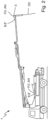
- the construction and/or thick matter pump 1 is designed as a mobile construction and/or thick matter pump, in particular as a car construction and/or thick matter pump, as in Fig. 2 shown.
- the delivery variable FG' is characteristic of an input of energy from the delivery piston 3a, 3b into the building and/or thick material DS.
- the feed quantity FG' is characteristic of the pressure, in particular the drive pressure, p acting on the building and/or thick material DS in the feed cylinder 2a, 2b, as shown in Fig. 4 shown.
- the conveying sensor device 5' comprises a pressure sensor device.
- the delivery quantity FG' is characteristic of an excitation AN of at least one part 8 of the construction and/or thick matter pump 1 caused by the introduction of energy from the delivery piston 3a, 3b into the construction and/or thick matter DS, as in Fig. 2 shown.
- the conveyor sensor device 5' has an excitation sensor device, in particular an acceleration sensor device and/or a rotation rate sensor device.
- the, in particular one, part 8 is the conveyor line 8', in particular on the car, and the, in particular other, part 8 is a Conveyor mast 8", in particular with the excitation sensor device of the conveyor sensor device 5' at a tip of the conveyor mast 8".
- the method further comprises: determining a displacement start position POVA, at which the delivery piston 3a, 3b begins to displace sucked building and/or thick material DS from the delivery cylinder 2a, 2b, by linking the detected position variable PGa, PGb during the movement for displacement and the detected delivery variable FG' characterizing the input of energy from the delivery piston 3a, 3b into the building and/or thick material DS during the movement for displacement, as in Fig. 4 shown, in particular by means of the determining device 6. Determining the profile PR based on the determined displacement start position POVA.
- the displacement start position POVA is determined by linking the detected position variables PGa, PGb during displacement and the detected conveying variable FG' during displacement.
- the displacement start position can be determined by linking the detected position variables during movement to the determining displacement start position and the detected conveying variable during movement to the determining displacement start position.
- the displacement start position POVA is determined as the position POa, POb of the delivery piston 3a, 3b at which the delivery variable FG', in particular the pressure p, reaches or exceeds a limit value FG'limit, in particular plimit.
- Fig. 4 the delivery piston 3a moves, in particular from a suction or stroke end position POAE, to the right, as shown by an arrow.
- the delivery piston 3a moves due to vacuum or displaces building and/or thick material DS that has not yet been sucked in.
- the pressure p is therefore low.
- the delivery piston 3a begins to displace or compress the building and/or thick material DS into a cylindrical shape, but not yet to displace it out of the delivery cylinder 2a.
- the pressure p therefore increases.
- the delivery piston 3a As soon as the delivery piston 3a has displaced or compressed the building and/or thick material DS into the cylindrical shape, the delivery piston 3a begins to displace the building and/or thick material DS out of the delivery cylinder 2a, in particular into the delivery line 8'. The pressure p therefore reaches or exceeds the limit value plimit. The displacement start position POVA is thus determined.
- the method comprises: determining a filling level FD of the conveyor cylinder 2a, 2b with building and/or thick material DS based on the determined displacement start position POVA, in particular by means of the determining device 6, as in Fig. 3 Determining the profile PR of a subsequent movement to the suction, in particular a subsequent suction, based on the determined filling degree FD, as in Fig. 6 shown. Controlling the subsequent movement to suction, in particular the subsequent suction, according to the determined profile PR.
- the method comprises: determining a time duration ZD for a previous movement for suction, in particular a previous suction, causing the determined displacement start position POVA and/or the determined filling level FD, as in Fig. 5 shown, in particular by means of the determining device 6. Determining a delivery quantity FM by linking the determined displacement start position POVA and/or the determined filling level FD and the determined time period ZD with each other, in particular by means of the determining device 6, as in Fig. 3 Determining the profile PR of the subsequent movement to the suction, in particular the subsequent suction, based on the determined flow rate FM, as shown in Fig. 6 shown.
- the method comprises: decreasing a speed v and/or increasing a standstill time SZD of the profile PR from a previous suction, as in Fig. 5 shown, to a subsequent suction, as in Fig. 6 shown, in particular by means of the determining device 6, until the displacement start position POVA no longer approaches the suction or stroke end position POAE and/or the filling level FD and/or the delivery rate FM no longer increase.
- a standard profile SPR in particular a standard acceleration and deceleration ramp, of the, in particular preceding, movement of the delivery piston 3a, 3b for the suction, in particular the preceding suction, of building and/or thick material DS with a standard viscosity is shown.
- the standard profile SPR is not optimal.
- the, in particular determined, displacement start position POVA is not maximally close to the suction or stroke end position POAE, of the, in particular specific filling level FD is not maximum and/or the specific flow rate FM is not maximum.
- the profile PR of the, in particular subsequent, movement of the delivery piston 3a, 3b for the suction, in particular the subsequent suction, of building and/or thick material DS is shown, in particular by adaptation, in particular and iteration.
- the profile PR has or has, in particular in contrast to the standard profile SPR, a high speed v at a suction or stroke start position or displacement or stroke end position POVE. This makes it possible to quickly generate a high initial suction vacuum.
- the profile PR has or has, in particular in contrast to the standard profile SPR, a high speed v in a middle between the displacement or stroke end position POVE and the suction or stroke end position POAE or the stroke HU. This makes it possible to have the, in particular determined, short time duration ZD.
- the PR profile particularly in contrast to the standard SPR profile, has or exhibits a low speed v and a long standstill time SZD at the suction or stroke end position POAE.
- This enables a high overrun effect.
- This thus enables a minimal vacuum.
- This thus enables the, in particular, determined, displacement start position POVA to be as close as possible to the suction or stroke end position POAE, the, in particular, determined, maximum filling level FD maximum and/or the, in particular, determined, maximum delivery rate FM.
Landscapes
- Engineering & Computer Science (AREA)
- Mechanical Engineering (AREA)
- General Engineering & Computer Science (AREA)
- Computer Hardware Design (AREA)
- Reciprocating Pumps (AREA)
- Control Of Positive-Displacement Pumps (AREA)
Applications Claiming Priority (3)
| Application Number | Priority Date | Filing Date | Title |
|---|---|---|---|
| DE102020207970.6A DE102020207970A1 (de) | 2020-06-26 | 2020-06-26 | Verfahren zum Betreiben einer Bau- und/oder Dickstoffpumpe zum Fördern von Bau- und/oder Dickstoff und Bau- und/oder Dickstoffpumpe zum Fördern von Bau- und/oder Dickstoff |
| PCT/EP2021/065100 WO2021259620A1 (fr) | 2020-06-26 | 2021-06-07 | Procédé pour faire fonctionner une pompe à matériau de construction et/ou à matériau visqueux pour transporter un matériau de construction et/ou un matériau visqueux, et pompe à matériau de construction et/ou à matériau visqueux pour transporter un matériau de construction et/ou un matériau visqueux |
| EP21731739.5A EP4172500B1 (fr) | 2020-06-26 | 2021-06-07 | Procédé pour faire fonctionner une pompe à matériau de construction et/ou à matériau visqueux pour transporter un matériau de construction et/ou un matériau visqueux, et pompe à matériau de construction et/ou à matériau visqueux pour transporter un matériau de construction et/ou un matériau visqueux |
Related Parent Applications (2)
| Application Number | Title | Priority Date | Filing Date |
|---|---|---|---|
| EP21731739.5A Division EP4172500B1 (fr) | 2020-06-26 | 2021-06-07 | Procédé pour faire fonctionner une pompe à matériau de construction et/ou à matériau visqueux pour transporter un matériau de construction et/ou un matériau visqueux, et pompe à matériau de construction et/ou à matériau visqueux pour transporter un matériau de construction et/ou un matériau visqueux |
| EP21731739.5A Division-Into EP4172500B1 (fr) | 2020-06-26 | 2021-06-07 | Procédé pour faire fonctionner une pompe à matériau de construction et/ou à matériau visqueux pour transporter un matériau de construction et/ou un matériau visqueux, et pompe à matériau de construction et/ou à matériau visqueux pour transporter un matériau de construction et/ou un matériau visqueux |
Publications (2)
| Publication Number | Publication Date |
|---|---|
| EP4579082A2 true EP4579082A2 (fr) | 2025-07-02 |
| EP4579082A3 EP4579082A3 (fr) | 2025-07-09 |
Family
ID=76392362
Family Applications (2)
| Application Number | Title | Priority Date | Filing Date |
|---|---|---|---|
| EP21731739.5A Active EP4172500B1 (fr) | 2020-06-26 | 2021-06-07 | Procédé pour faire fonctionner une pompe à matériau de construction et/ou à matériau visqueux pour transporter un matériau de construction et/ou un matériau visqueux, et pompe à matériau de construction et/ou à matériau visqueux pour transporter un matériau de construction et/ou un matériau visqueux |
| EP25176927.9A Pending EP4579082A3 (fr) | 2020-06-26 | 2021-06-07 | Procédé pour faire fonctionner une pompe à matériau de construction et/ou à matériau visqueux pour transporter pompe à matériau de construction et/ou à matériau visqueux pour transporter un matériau de construction et/ou un matériau visqueux |
Family Applications Before (1)
| Application Number | Title | Priority Date | Filing Date |
|---|---|---|---|
| EP21731739.5A Active EP4172500B1 (fr) | 2020-06-26 | 2021-06-07 | Procédé pour faire fonctionner une pompe à matériau de construction et/ou à matériau visqueux pour transporter un matériau de construction et/ou un matériau visqueux, et pompe à matériau de construction et/ou à matériau visqueux pour transporter un matériau de construction et/ou un matériau visqueux |
Country Status (7)
| Country | Link |
|---|---|
| US (1) | US20230265843A1 (fr) |
| EP (2) | EP4172500B1 (fr) |
| JP (1) | JP7813248B2 (fr) |
| KR (1) | KR102956067B1 (fr) |
| CN (1) | CN115917145A (fr) |
| DE (1) | DE102020207970A1 (fr) |
| WO (1) | WO2021259620A1 (fr) |
Families Citing this family (5)
| Publication number | Priority date | Publication date | Assignee | Title |
|---|---|---|---|---|
| DE102023200687A1 (de) * | 2023-01-27 | 2024-08-01 | Putzmeister Engineering Gmbh | Verfahren zum Betreiben einer Baumaschine und Baumaschine |
| DE102023120153A1 (de) * | 2023-07-28 | 2025-01-30 | Putzmeister Engineering Gmbh | Verfahren zum Betreiben eines Bau- und/oder Dickstoffpumpensystems zum Fördern von Bau- und/oder Dickstoff und Bau- und/oder Dickstoffpumpensystem zum Fördern von Bau- und/oder Dickstoff |
| DE102024102114A1 (de) | 2024-01-25 | 2025-07-31 | Putzmeister Engineering Gmbh | Verfahren, Bau- und/oder Dickstofffördersystem und Verwendung |
| DE102024103029A1 (de) * | 2024-02-02 | 2025-08-07 | Putzmeister Engineering Gmbh | Verfahren zum Betreiben eines Bau- und/oder Dickstoffpumpensystems und Bau- und/oder Dickstoffpumpensystem |
| DE102024120629A1 (de) * | 2024-07-19 | 2026-01-22 | INSTATIQ GmbH | Verfahren und Bau- und/oder Dickstofffördersystem |
Citations (2)
| Publication number | Priority date | Publication date | Assignee | Title |
|---|---|---|---|---|
| US6779983B1 (en) | 2001-10-05 | 2004-08-24 | David A. Olson | Sludge pump with management system |
| DE102013104494A1 (de) | 2013-05-02 | 2014-11-06 | MPS-Matter Pumpsysteme GmbH | Dickstoffpumpe |
Family Cites Families (14)
| Publication number | Priority date | Publication date | Assignee | Title |
|---|---|---|---|---|
| US5388965A (en) * | 1990-10-10 | 1995-02-14 | Friedrich Wilhelm Schwing Gmbh | Sludge pump with monitoring system |
| DE4035518C2 (de) * | 1990-11-08 | 1994-06-09 | Putzmeister Maschf | Verfahren und Anordnung zur meßtechnischen Bestimmung des Volumenstroms von mittels einer Kolbendickstoffpumpe transportiertem Fördergut |
| DE4208754A1 (de) * | 1992-03-19 | 1993-09-23 | Schwing Gmbh F | Dickstoffpumpe mit foerderzylindern, insbesondere zweizylinderbetonpumpe |
| ES2090741T3 (es) * | 1992-03-21 | 1996-10-16 | Schwing Gmbh F | Bomba para materiales consistentes. |
| DE4214109C2 (de) * | 1992-04-29 | 1994-07-28 | Abel Gmbh & Co | Feststoffpumpe |
| JPH0742667A (ja) * | 1993-07-01 | 1995-02-10 | Ishigaki Mech Ind Co | 重粘性物の搬送装置 |
| JP4409220B2 (ja) * | 2003-07-17 | 2010-02-03 | 古河機械金属株式会社 | ピストンポンプの逆流防止予圧機構 |
| DE102004029231A1 (de) * | 2003-12-17 | 2005-07-21 | Ksb Aktiengesellschaft | Drucktauschersystem |
| DE102004015415A1 (de) | 2004-03-26 | 2005-10-13 | Putzmeister Ag | Vorrichtung und Verfahren zur Steuerung einer Zweizylinder-Dickstoffpumpe |
| DE102004015416A1 (de) * | 2004-03-26 | 2005-10-13 | Putzmeister Ag | Vorrichtung und Verfahren zur Steuerung einer Dickstoffpumpe |
| JP2011241725A (ja) * | 2010-05-17 | 2011-12-01 | Ihi Construction Machinery Ltd | ピストン式コンクリートポンプの制御装置 |
| JP6008524B2 (ja) * | 2012-03-16 | 2016-10-19 | 極東開発工業株式会社 | コンクリートポンプ |
| DE102012216242A1 (de) * | 2012-09-13 | 2014-03-13 | Putzmeister Engineering Gmbh | Vorrichtung zur Antriebssteuerung einer Zweizylinder-Dickstoffpumpe |
| DE102023110126B3 (de) * | 2023-04-20 | 2024-05-08 | Putzmeister Engineering Gmbh | Dickstoffpumpe und Verfahren zum Betrieb einer Dickstoffpumpe |
-
2020
- 2020-06-26 DE DE102020207970.6A patent/DE102020207970A1/de active Pending
-
2021
- 2021-06-07 KR KR1020227044354A patent/KR102956067B1/ko active Active
- 2021-06-07 JP JP2022577142A patent/JP7813248B2/ja active Active
- 2021-06-07 WO PCT/EP2021/065100 patent/WO2021259620A1/fr not_active Ceased
- 2021-06-07 CN CN202180045057.1A patent/CN115917145A/zh active Pending
- 2021-06-07 EP EP21731739.5A patent/EP4172500B1/fr active Active
- 2021-06-07 US US18/012,712 patent/US20230265843A1/en active Pending
- 2021-06-07 EP EP25176927.9A patent/EP4579082A3/fr active Pending
Patent Citations (2)
| Publication number | Priority date | Publication date | Assignee | Title |
|---|---|---|---|---|
| US6779983B1 (en) | 2001-10-05 | 2004-08-24 | David A. Olson | Sludge pump with management system |
| DE102013104494A1 (de) | 2013-05-02 | 2014-11-06 | MPS-Matter Pumpsysteme GmbH | Dickstoffpumpe |
Also Published As
| Publication number | Publication date |
|---|---|
| KR102956067B1 (ko) | 2026-04-23 |
| DE102020207970A1 (de) | 2021-12-30 |
| EP4172500A1 (fr) | 2023-05-03 |
| EP4579082A3 (fr) | 2025-07-09 |
| KR20230027047A (ko) | 2023-02-27 |
| EP4172500B1 (fr) | 2025-07-30 |
| WO2021259620A1 (fr) | 2021-12-30 |
| JP7813248B2 (ja) | 2026-02-12 |
| CN115917145A (zh) | 2023-04-04 |
| US20230265843A1 (en) | 2023-08-24 |
| JP2023530943A (ja) | 2023-07-20 |
Similar Documents
| Publication | Publication Date | Title |
|---|---|---|
| EP4172500B1 (fr) | Procédé pour faire fonctionner une pompe à matériau de construction et/ou à matériau visqueux pour transporter un matériau de construction et/ou un matériau visqueux, et pompe à matériau de construction et/ou à matériau visqueux pour transporter un matériau de construction et/ou un matériau visqueux | |
| DE112009003826B4 (de) | Hydrauliksteuerungssystem mit Strömungskraftkompensation | |
| EP2362102B1 (fr) | Agrégat de pompes de dosage | |
| EP2550454B1 (fr) | Procédé de commande d'une pompe doseuse | |
| DE102013104494B4 (de) | Dickstoffpumpe | |
| EP3807534B1 (fr) | Système d'entraînement hydraulique pour une pompe à matériaux de construction et pompe à matériaux de construction | |
| DE19948602A1 (de) | Schüttgutpumpenvorrichtung | |
| EP4088027B1 (fr) | Procédé de fonctionnement d'une pompe à solides haute densité et pompe à solides haute densité | |
| WO2015067584A1 (fr) | Pompe pour liquide épais et unité d'amenée | |
| EP4305304B1 (fr) | Procédé pour faire fonctionner une pompe à matériau de construction et/ou à matériau visqueux destinée au transport de matériaux de construction et/ou de matériaux visqueux, et pompe à matériau de construction et/ou à matériau visqueux destinée au transport de matériaux de construction et/ou de matériaux visqueux | |
| DE2054197A1 (de) | Vorrichtung fur Effektregelung von Pumpen | |
| EP3803117B1 (fr) | Dispositif pour pomper des fluides visqueux | |
| DE2737062C2 (fr) | ||
| DE4405234C1 (de) | Vorrichtung zur Summenleistungsregelung von wenigstens zwei hydrostatischen Verstellpumpen | |
| WO2012084093A1 (fr) | Mécanisme d'entraînement hydraulique | |
| WO2025026643A1 (fr) | Procédé de fonctionnement d'un système de pompe à matériau de construction et/ou à matière épaisse | |
| DE10031892A1 (de) | Verfahren zur Steuerung der Geschwindigkeit eines elektrohydraulischen Hubantriebs | |
| DE102021212099A1 (de) | Mobile Arbeitsmaschine, Verfahren und Verwendung der mobilen Arbeitsmaschine | |
| EP1332288B1 (fr) | Procede de commande d'un systeme de pompes compose de deux pompes a pistons plongeurs a commande hydraulique | |
| DE102023115806A1 (de) | Hydrauliksystem, Bau- und/oder Dickstoffpumpe und Verfahren | |
| DE102009021323A1 (de) | Elektrohydraulisches Reglersystem | |
| AT519018B1 (de) | Verfahren zur Optimierung einer Bohrloch-Förderleistung | |
| WO2023088857A1 (fr) | Procédé et agencement de transport pour transporter un fluide à partir d'un trou de forage | |
| DE3013733A1 (de) | Vorrichtung zum ausgleich von druckverlusten | |
| WO2018001547A1 (fr) | Transmission hydrostatique en circuit fermé et procédé pour faire fonctionner ladite transmission |
Legal Events
| Date | Code | Title | Description |
|---|---|---|---|
| PUAI | Public reference made under article 153(3) epc to a published international application that has entered the european phase |
Free format text: ORIGINAL CODE: 0009012 |
|
| STAA | Information on the status of an ep patent application or granted ep patent |
Free format text: STATUS: THE APPLICATION HAS BEEN PUBLISHED |
|
| REG | Reference to a national code |
Ref country code: DE Ref legal event code: R079 Free format text: PREVIOUS MAIN CLASS: F04B0049200000 Ipc: F04B0007000000 |
|
| PUAL | Search report despatched |
Free format text: ORIGINAL CODE: 0009013 |
|
| AC | Divisional application: reference to earlier application |
Ref document number: 4172500 Country of ref document: EP Kind code of ref document: P |
|
| AK | Designated contracting states |
Kind code of ref document: A2 Designated state(s): AL AT BE BG CH CY CZ DE DK EE ES FI FR GB GR HR HU IE IS IT LI LT LU LV MC MK MT NL NO PL PT RO RS SE SI SK SM TR |
|
| AK | Designated contracting states |
Kind code of ref document: A3 Designated state(s): AL AT BE BG CH CY CZ DE DK EE ES FI FR GB GR HR HU IE IS IT LI LT LU LV MC MK MT NL NO PL PT RO RS SE SI SK SM TR |
|
| RIC1 | Information provided on ipc code assigned before grant |
Ipc: F04B 49/20 20060101ALI20250605BHEP Ipc: F04B 49/10 20060101ALI20250605BHEP Ipc: F04B 49/06 20060101ALI20250605BHEP Ipc: F04B 15/02 20060101ALI20250605BHEP Ipc: F04B 9/117 20060101ALI20250605BHEP Ipc: F04B 7/00 20060101AFI20250605BHEP |
|
| STAA | Information on the status of an ep patent application or granted ep patent |
Free format text: STATUS: REQUEST FOR EXAMINATION WAS MADE |
|
| 17P | Request for examination filed |
Effective date: 20251229 |