EP4579095A1 - Befestigungsvorrichtung - Google Patents
Befestigungsvorrichtung Download PDFInfo
- Publication number
- EP4579095A1 EP4579095A1 EP24220770.2A EP24220770A EP4579095A1 EP 4579095 A1 EP4579095 A1 EP 4579095A1 EP 24220770 A EP24220770 A EP 24220770A EP 4579095 A1 EP4579095 A1 EP 4579095A1
- Authority
- EP
- European Patent Office
- Prior art keywords
- nut
- screw
- deflection
- protrusion
- flange
- Prior art date
- Legal status (The legal status is an assumption and is not a legal conclusion. Google has not performed a legal analysis and makes no representation as to the accuracy of the status listed.)
- Pending
Links
Images



Classifications
-
- F—MECHANICAL ENGINEERING; LIGHTING; HEATING; WEAPONS; BLASTING
- F16—ENGINEERING ELEMENTS AND UNITS; GENERAL MEASURES FOR PRODUCING AND MAINTAINING EFFECTIVE FUNCTIONING OF MACHINES OR INSTALLATIONS; THERMAL INSULATION IN GENERAL
- F16B—DEVICES FOR FASTENING OR SECURING CONSTRUCTIONAL ELEMENTS OR MACHINE PARTS TOGETHER, e.g. NAILS, BOLTS, CIRCLIPS, CLAMPS, CLIPS OR WEDGES; JOINTS OR JOINTING
- F16B37/00—Nuts or like thread-engaging members
- F16B37/04—Devices for fastening nuts to surfaces, e.g. sheets, plates
- F16B37/06—Devices for fastening nuts to surfaces, e.g. sheets, plates by means of welding or riveting
- F16B37/062—Devices for fastening nuts to surfaces, e.g. sheets, plates by means of welding or riveting by means of riveting
- F16B37/065—Devices for fastening nuts to surfaces, e.g. sheets, plates by means of welding or riveting by means of riveting by deforming the material of the nut
- F16B37/067—Devices for fastening nuts to surfaces, e.g. sheets, plates by means of welding or riveting by means of riveting by deforming the material of the nut the material of the nut being deformed by a threaded member generating axial movement of the threaded part of the nut, e.g. blind rivet type
-
- F—MECHANICAL ENGINEERING; LIGHTING; HEATING; WEAPONS; BLASTING
- F16—ENGINEERING ELEMENTS AND UNITS; GENERAL MEASURES FOR PRODUCING AND MAINTAINING EFFECTIVE FUNCTIONING OF MACHINES OR INSTALLATIONS; THERMAL INSULATION IN GENERAL
- F16B—DEVICES FOR FASTENING OR SECURING CONSTRUCTIONAL ELEMENTS OR MACHINE PARTS TOGETHER, e.g. NAILS, BOLTS, CIRCLIPS, CLAMPS, CLIPS OR WEDGES; JOINTS OR JOINTING
- F16B37/00—Nuts or like thread-engaging members
- F16B37/04—Devices for fastening nuts to surfaces, e.g. sheets, plates
- F16B37/041—Releasable devices
Definitions
- the present invention relates to the technical field of mechanical fastening devices, more precisely to clearance nuts used to secure components in vehicles, such as those present on a dashboard.
- nuts are commonly used to secure various components in a vehicle. These components can include gauges, glove boxes, and other components commonly mounted on the dashboard.
- these nuts may be designed to be removable to allow for the removal or replacement of fasteners.
- the removal process can be difficult and may risk damaging the nut or causing it to fall inside the dashboard, which can cause unwanted noise.
- the nut may begin to rotate, which can potentially cause shock if tightened quickly. This shock can potentially damage the nut, for example, by breaking the connecting straps.
- the present invention aims to overcome these drawbacks by providing a free-floating nut, which ensures the stability of the nut during the screwing process, prevents shocks during screwing and facilitates the disassembly process without causing damage or unwanted noise.
- the present invention relates to the deflection nut which comprises a collar serving as a contact surface and a body part, the collar and the body part are connected to each other by two opposite connecting straps having an elastic deformation towards the outside, the deflection nut is provided with a screw passage comprising a first fixing hole in the central part of the collar and a second fixing hole in the body part.
- a protrusion protruding toward the body portion is formed on a surface of the flange, and an insertion recess into which the protrusion is inserted is formed in the body portion;
- a protrusion projecting toward a surface of the flange is formed in the body portion, and an insertion recess into which the protrusion is inserted is formed on the surface of the collar.
- the clearance nut is provided with two diagonally arranged ribs which connect the collar to the connecting straps, said ribs being designed to come into contact with a sheet metal.
- the connecting straps include retaining notches located near the collar.
- the retaining notches are arranged in the form of stages, and the connecting straps have bulges located between two stages of the retaining notches.
- the protrusion has a rectilinear shape, and optionally, the protrusion comprises two parts separated by the screw passage.
- the protrusion is retracted into a state of close contact with an interior surface of the insertion recess when a screw is fastened.
- the opposing connecting straps each have a substantially V shape as they diverge outwardly.
- the clearance nut is made of plastic.
- the deflection nut is made of metal.
- an assembly comprises the deflection nut according to the present invention and a screw.
- the clearance nut 100 according to the invention can be manufactured by molding known plastic material, for example by thermoplastic injection, more particularly in technical plastics such as polyamides, acetal resins, thermoplastic polyesters.
- the clearance nut 100 is made of known materials capable of resisting aging and temperature.
- the clearance nut 100 according to the invention may be made of metal.
- the deflection nut is shown in a front view, highlighting the general design and arrangement of its components.
- the deflection nut designated by the reference numeral 100, includes a flange 120 at one end, which serves as a contact surface for interfacing with other components, such as a dashboard 300 or a support part.
- the flange 120 preferably in the center, is provided with a first fixing hole 122, which is part of the screw passage 150 which allows the insertion and fixing of a screw 200.
- a protrusion 124 On the surface of the flange 120, there is a protrusion 124, which is adapted to protrude towards the body portion 160 of the deflection nut 100.
- This protrusion 124 is a structural feature which can engage with a corresponding insertion recess 184 in the body portion 160 to facilitate alignment and stability of the nut when assembled.
- the body portion 160 of the deflection nut 100 is connected to the collar 120 by two opposing connecting straps 140.
- These straps 140 are designed to have outward elastic deformation, which allows for flexibility and resilience in the structure of the nut.
- the connecting straps 140 are essential to the ability of the deflection nut to maintain its position and resist rotation when the screw 200 is secured.
- FIG. 2 illustrates the alignment and positioning of the first fixing hole 122 in the collar 120, providing a clear view of its location and its role in the assembly of the deflection nut with a screw 200.
- the representation of the first fastening hole 122 relative to the screw passage 150 is an aspect of the deflection nut that is central to its function as a fastening device. This view helps convey the ease with which the screw 200 can be aligned and inserted into the deflection nut 100.
- FIG. 3 shows the interaction between the protrusion 124 and the insertion recess 184, demonstrating how the protrusion 124 fits into the recess 184 to secure the position of the deflection nut.
- the sectional view also shows a clear representation of the screw passage 150, which includes the first fixing hole 122 in the collar 120 and the second fixing hole 162 in the body portion 160, through which the screw 200 is intended to pass.
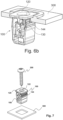
- This figure shows the orientation and alignment of the deflection nut and screw relative to the backing sheet and demonstrates that the deflection nut is designed to be easily positioned on the backing sheet, with the screw then inserted and tightened to complete the attachment.
- FIG 8 shows a sectional view of an assembly consisting of a clearance nut and a screw engaged in a support part. This view is essential to illustrate the interaction between the 100 travel nut and the 200 screw during the fastening process.
- the deflection nut 100 is shown in its operational state, with the screw 200 having been inserted through the backing sheet and tightened in place.
- the flange 120 of the deflection nut is in direct contact with the backing sheet, acting as a stable base that distributes the force of the tightened screw over a larger area, thereby reducing stress concentrations and potential damage to the backing sheet.
- the protrusion 124 is engaged with the insertion recess 184, which is a design feature that prevents the deflection nut from rotating or moving during the tightening process. This engagement ensures that the deflection nut remains properly aligned with the screw passage 150, allowing for a secure and stable connection that resists loosening over time.
- the connecting straps 140 provide the deflection nut with the flexibility to accommodate slight misalignments and absorb vibrations, which may be particularly useful in automotive applications where the deflection nut may be subjected to dynamic loads. If the design includes bulges 145 and retaining notches 144, these would contribute to the ability of the deflection nut to maintain its position and resist deformation under the tightened screw.
- the sectional view of the Figure 9 is a clear representation of the deflection nut in its final locked position within an assembly. It demonstrates the secure fixation achieved by the design of the deflection nut and screw, highlighting the effectiveness of the features of the deflection nut to provide a stable and reliable fastening solution. This figure serves as a visual guide to understanding the fully assembled state of the deflection nut and its interaction with the screw and backing sheet.
- a suitable tool such as a screwdriver or power drill
- a suitable tool such as a screwdriver or power drill
- Tables 1 References Designations 100 Deflection nut 120 Collar 160 Body part 140 Connecting straps 150 Screw passage 122 First fixing hole 162 Second fixing hole 164 Barrel nut 124 Protuberance 200 Screw 130 Rib 300 Support panel/Dashboard 144 Holding notch 145 Bulges 184 Insert recess
Landscapes
- Engineering & Computer Science (AREA)
- General Engineering & Computer Science (AREA)
- Mechanical Engineering (AREA)
- Connection Of Plates (AREA)
Applications Claiming Priority (1)
| Application Number | Priority Date | Filing Date | Title |
|---|---|---|---|
| FR2315441A FR3157906A1 (fr) | 2023-12-28 | 2023-12-28 | Dispositif de fixation |
Publications (1)
| Publication Number | Publication Date |
|---|---|
| EP4579095A1 true EP4579095A1 (de) | 2025-07-02 |
Family
ID=90971455
Family Applications (1)
| Application Number | Title | Priority Date | Filing Date |
|---|---|---|---|
| EP24220770.2A Pending EP4579095A1 (de) | 2023-12-28 | 2024-12-17 | Befestigungsvorrichtung |
Country Status (2)
| Country | Link |
|---|---|
| EP (1) | EP4579095A1 (de) |
| FR (1) | FR3157906A1 (de) |
Citations (4)
| Publication number | Priority date | Publication date | Assignee | Title |
|---|---|---|---|---|
| US3313083A (en) * | 1963-05-29 | 1967-04-11 | Tinnerman Products Inc | Deformable plastic fastener |
| GB1065578A (en) * | 1964-08-05 | 1967-04-19 | A A Rice Inc | Self-anchoring device for lodging in a workpiece aperture to retain a screw-threaded member therein |
| JPS5039661U (de) * | 1973-07-14 | 1975-04-23 | ||
| US4089248A (en) * | 1975-05-21 | 1978-05-16 | National Molding Corporation | Self-locking unitary molded plastic fastener |
-
2023
- 2023-12-28 FR FR2315441A patent/FR3157906A1/fr active Pending
-
2024
- 2024-12-17 EP EP24220770.2A patent/EP4579095A1/de active Pending
Patent Citations (4)
| Publication number | Priority date | Publication date | Assignee | Title |
|---|---|---|---|---|
| US3313083A (en) * | 1963-05-29 | 1967-04-11 | Tinnerman Products Inc | Deformable plastic fastener |
| GB1065578A (en) * | 1964-08-05 | 1967-04-19 | A A Rice Inc | Self-anchoring device for lodging in a workpiece aperture to retain a screw-threaded member therein |
| JPS5039661U (de) * | 1973-07-14 | 1975-04-23 | ||
| US4089248A (en) * | 1975-05-21 | 1978-05-16 | National Molding Corporation | Self-locking unitary molded plastic fastener |
Also Published As
| Publication number | Publication date |
|---|---|
| FR3157906A1 (fr) | 2025-07-04 |
Similar Documents
| Publication | Publication Date | Title |
|---|---|---|
| FR2700367A1 (fr) | Dispositif de fixation comportant un élément de compression. | |
| FR2780756A1 (fr) | Systeme de blocage a boulon et ecrou | |
| WO2001002739A1 (fr) | Dispositif d'assemblage de deux pieces presentant un jeu de position | |
| EP1178894A1 (de) | Vorrichtung zur befestigung eines radiators an einer fahrzeughalterung | |
| WO2021111055A1 (fr) | Rivet a expansion | |
| EP3891405B1 (de) | Axial zentrierte vierteldrehungsbefestigungsvorrichtung | |
| FR3157906A1 (fr) | Dispositif de fixation | |
| FR2962503A3 (fr) | Ensemble de fixation | |
| EP2529960A1 (de) | Radaufhängungslager, das mit Montagezungen ausgestattet ist | |
| EP3191719A1 (de) | Körper zur geräuschdämpfenden montage einer vorrichtung auf einer stützwand mit vorhaltevorrichtung | |
| EP1588897B1 (de) | Haltemittel und zugehöriges Fahrzeug | |
| EP4416397B1 (de) | Befestigungsvorrichtung | |
| FR2890121A1 (fr) | Couvercle superieur de soupapes | |
| EP3913237B1 (de) | Befestigungsvorrichtung | |
| EP2694826A1 (de) | Vorrichtung zur befestigung einer montageschraube an einem element vor der fixierung an einem anderen element | |
| EP4148289A1 (de) | Vorgeschnittenes zwischenelement zur herstellung einer zwischenscheibe, die zwischen teilen einer anordnung positioniert ist, und verfahren zum zusammenbau von mindestens zwei teilen unter verwendung mindestens eines solchen vorgeschnittenen zwischenelements | |
| FR2933757A1 (fr) | Ensemble de palier a roulement | |
| EP1649472B1 (de) | Elektromagnetisches ventil, verfahren zum anbringen einer solenoidspule an dem elektromagnetischen ventil und verfahren zum ablösen der solenoidspule von diesem elektromagnetischen ventil | |
| FR3005123A1 (fr) | Dispositif pour la fixation de deux pieces entre elles | |
| FR2984942A1 (fr) | Procede de montage et ensemble de serrure pour ouvrant de vehicule automobile | |
| WO2013110645A1 (fr) | Procédé de montage et ensemble de serrure pour ouvrant de véhicule automobile | |
| FR2983443A1 (fr) | Ensemble pour vehicule automobile, notamment pour l'assemblage d'un pare-chocs et d'un elargisseur de pare-chocs | |
| EP3409567A1 (de) | Haltevorrichtung für armaturenbrett eines kraftfahrzeugs | |
| FR3157481A1 (fr) | Rivet d'expansion | |
| EP3154844B1 (de) | Vorrichtung zur befestigung eines zubehörs an einem kraftstofftank eines kraftfahrzeugs |
Legal Events
| Date | Code | Title | Description |
|---|---|---|---|
| PUAI | Public reference made under article 153(3) epc to a published international application that has entered the european phase |
Free format text: ORIGINAL CODE: 0009012 |
|
| STAA | Information on the status of an ep patent application or granted ep patent |
Free format text: STATUS: THE APPLICATION HAS BEEN PUBLISHED |
|
| AK | Designated contracting states |
Kind code of ref document: A1 Designated state(s): AL AT BE BG CH CY CZ DE DK EE ES FI FR GB GR HR HU IE IS IT LI LT LU LV MC ME MK MT NL NO PL PT RO RS SE SI SK SM TR |
|
| STAA | Information on the status of an ep patent application or granted ep patent |
Free format text: STATUS: REQUEST FOR EXAMINATION WAS MADE |
|
| 17P | Request for examination filed |
Effective date: 20251219 |
|
| STAA | Information on the status of an ep patent application or granted ep patent |
Free format text: STATUS: EXAMINATION IS IN PROGRESS |
|
| 17Q | First examination report despatched |
Effective date: 20260603 |